DELTEC Cadd Legacy Infusion Pump Service Manual - internetMED
DELTEC Cadd Legacy Infusion Pump Service Manual - internetMED
DELTEC Cadd Legacy Infusion Pump Service Manual - internetMED

Create successful ePaper yourself
Turn your PDF publications into a flip-book with our unique Google optimized e-Paper software.
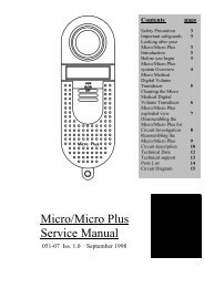
Intermittent Delivery Battery Life with Alkaline BatteriesDose Volume Duration Dose Cycle KVO Life Volume23.5 ml 1:00 hr 5:00 hr 0.2 ml/hr 193 hr 915 ml61 ml 1:00 hr 6:00 hr 0.2 ml/hr 120 hr 1224 ml125 ml 1:00 hr 6:00 hr 0.2 ml/hr 65 hr 1356 mlTable 6. Two AA Alkaline-type batteries used with the CADD-<strong>Legacy</strong> pumps.Rate (ml/hr)135120105907560453015010 20 30 40 50 60 70 80 90Hours100Figure 5. Operating time to low battery alarm using alkaline batteries.Rate (ml/hr)18161412108642050 100 150 200 250 300Hours350Figure 6. Operating time to low battery alarm using alkaline batteries.9
Continuous Delivery Battery Life with Lithium BatteriesRate Life Volume0.4 ml/hr 413 hrs 165 ml4 ml/hr 307 hrs 1228 ml10 ml/hr 190 hrs 1900 ml15 ml/hr 163 hrs 2445 ml30 ml/hr 90 hrs 2700 ml75 ml/hr 33 hrs 2475 ml125 ml/hr 22 hrs 2750 mlTable 7. Two AA Lithium-type batteries used with the CADD-<strong>Legacy</strong> pumps.Intermittent Delivery Battery Life with Lithium BatteriesDose Volume Duration Dose Cycle KVO Life Volume23.5 ml 1:00 hr 5:00 hr 0.2 ml/hr 300 hrs 1458 ml61 ml 1:00 hr 6:00 hr 0.2 ml/hr 185 hrs 1911 ml125 ml 1:00 hr 6:00 hr 0.2 ml/hr 125 hrs 2625 mlTable 8. Two AA Lithium-type batteries used with the CADD-<strong>Legacy</strong> pumps.Rate (ml/hr)135120105907560453015020 40 60 80 100 120 140 160 180Hours200Figure 7. Dual-stroke operating time on lithium batteries.Rate (ml/hr)18161412108642050 100 150 200 250 300 350 400Hours450Figure 8. Single-stroke operating time on lithium batteries.10
4 ConstructionThe pump’s housing is made of a special highimpact plastic. It is composed of two sections:the rear and front housing. The pump housingis sealed to ensure that the pump is waterresistant. The battery compartment is notwater resistant.NOTE:The CADD-<strong>Legacy</strong> ambulatory infusionpump is water resistant, but not waterproof.The pump is “Splashproof” and ischaracterized by the IEC code of IPX4.The battery compartment is accessed through aremovable door on the rear housing. Withinthe battery compartment is space for thebatteries and the four battery contacts.On CADD-<strong>Legacy</strong> pumps the MedicationCassette Reservoir or the administration set isattached to the bottom of the pump by insertingthe two hooks on the cassette into the matinghinge pins on the pump. The pump and thereservoir or the administration set are thenplaced in an upright position on a firm, flatsurface. The reservoir or the administration setmust be secured in place by inserting a coin (orkey if using the CADD-<strong>Legacy</strong> PCA pump) inthe slot on the pump’s locking button, pushingthe button in and turning the button onequarterturn counter-clockwise.NOTE:The Medication Cassette Reservoir and theadministration set are intended for singleuse only.The keyboard, located on the front housing, iscomposed of eight membrane switches (ninemembrane switches on the CADD-<strong>Legacy</strong> PCA pump) and is sealed against moisture. Allof the keys contain domes to provide a tactilefeel when the key is pressed. The keyboardkeys are sensed by the pump’s microprocessor.The Liquid Crystal Display (LCD), also locatedon the front housing, shows the pump statusand programmed settings. The dot matrixdisplay consists of 16 character columns with 2rows of characters, and is selected by thepump’s microprocessor according to statusconditions and keyboard entries.The microprocessor and other circuitry whichcontrol the pump are located on a printedcircuit board. The board contains the CentralProcessing Unit (CPU), motor driver circuitry,and other circuitry. The circuitry is designed toreduce susceptibility to interference fromelectromagnetic fields and to dissipate electrostaticdischarge.The LCD controller is mounted on the LCDusing chip on glass technology.The pumping mechanism subassembly containsthe motor, gear train, camshaft, valves, expulsor,sensing disk, infrared light source, infrareddetector, occlusion sensors, disposable sensor,and cassette locking button. Via the motordriver circuitry, the pump’s microprocessorcontrols motor rotation.Two external port connectors are utilized forremote dose and external power input. Theaccessory jack is used for attachment of theRemote Dose Cord (CADD-<strong>Legacy</strong> PCApump only) and interface cable. The RemoteDose Cord enables the patient to use either oftwo options to begin a Demand Dose whenusing the PCA delivery mode: (1) the RemoteDose button; or (2) the Í key.The second port allows connection to an ACadapter.The keyboard is connected to the printedcircuit board via a flex circuit tail. Discretewires connect the pumping mechanism, motor,and sensors to the printed circuit board.The accessory jack in conjunction with theinterface cable allows download of eventsusing the CADD-DIPLOMAT software.11
5 Theory of OperationKeyboard CircuitryThe CADD-<strong>Legacy</strong> pumps are controlled by amicroprocessor. The actions of the microprocessorare controlled by a program, which iscontained in the memory.Commands are issued to the microprocessorfrom the user via the eight keys on the keyboard(nine keys and Remote Dose Cord onCADD-<strong>Legacy</strong> PCA pump). The keys on thekeyboard are arranged in a 3x3 matrix whichfeeds into the keyboard encoder. A key closureapplies a ground to the associated input of thekeyboard encoder. Key debounce circuitryresident in the keyboard encoder provides aclean output signal to the microprocessor forthe duration of the key closure. The microprocessorreads keyboard status by accessingspecial memory locations in the keyboardencoder.The Remote Dose Cord button (CADD-<strong>Legacy</strong> PCA pump only) consists of an SPDT switchwith one switch output going to the microprocessorand the other going to the keyboardencoder. The switch has a common input lineand two output signal lines. The two signal linesare complementary such that one line is alwayslogic high and the other is always low. Whenthe Remote Dose Cord button is pressed, bothsignal lines change to the alternate logic state.This redundancy prevents a single line failurefrom starting a dose delivery.The Å button allows the pump to be placed in avery low power mode by turning off all sensorsand LCD, but some battery energy is still used bythe electronics. To maximize battery life, removethe batteries when pump is not in use.Data Memory in Real Time ClockRAMMany settings of the pump’s delivery andrecord-keeping parameters are stored by themicroprocessor in a Battery backed RAM in theReal Time Clock. Data to and from the memoryis presented serially. Whenever the microprocessoruses data from the Real Time Clock, thedata is checked for validity.EEPROMData describing the current delivery protocol isstored in an EEPROM included in the microprocessor.Whenever this data is used, it ischecked for validity.Battery Backed RAMAdditional settings of the pump’s delivery andrecord keeping parameters are stored in abattery backed Random Access Memory(RAM). Battery backup is provided by aprinted circuit board-mounted lithium battery.This battery provides a minimum of five yearsof memory retention during normal pumpusage. Whenever the microprocessor uses datafrom the RAM, the data is checked for validity.Time Base CircuitryAn accurate 3.6864 MHz timebase is providedby a quartz crystal. The 3.6864 MHz signal isconnected to the microprocessor, where it isfrequency-divided to access the programmemory at a cycle rate of 921 kHz.In addition, an accurate 32.768 kHz timebaseis provided by a second quartz crystal. The32.768 kHz signal is used for the real timeclock.LCD CircuitryThe CADD-<strong>Legacy</strong> pumps feature a 2 line by16 character Liquid Crystal Display (LCD).The characters on this dot matrix display areformed by a matrix of 5 by 7 dots. It is reflectiveonly, with a black on silver appearance,with no backlight.The display includes a controller chip mounteddirectly on the glass capable of interfacing with4 and 8 bit systems to display 92 kinds ofcharacters, numerals, symbols, and specialcharacters under control of a built in charactergenerator ROM. A RAM is also included tomake other special characters possible.12
LED IndicatorA green Light Emitting Diode (LED) is providedunder the pump’s front panel overlay toprovide pump power status to the user. Whenthis LED is lit, it indicates that an AC adapteris being used to power the pump.Flash PROM TechnologyProgram memory for the pump is stored inFlash Programmable Read Only Memory(Flash PROM). This type of memory allowsmodification of the contents without physicallyremoving the device from the circuit board.Under certain circumstances the program canalso be downloaded. Several layers of redundancyin the programming system preventaccidental erasing or modification of thePROM.Audible Alarm CircuitryAudible alarm circuitry consists of two piezoelectric disks and an independent oscillator.The disks flex or bend in resonance with theoutput of the oscillator. The piezo disks aremounted to the pump housing to enhancesound level.The microprocessor controls the audible alarmby selecting the alarm control line for morethan 0.5 seconds. The oscillator which drivesthe piezo disks is capable of providing twodriving frequencies. The low frequency is in therange of 700 to 1500 Hz and the high frequencyis in the range of 1600 to 2500 Hz.When the microprocessor selects the audiblealarm, the alarm enters a warble mode where itoscillates between the low and high frequencysound at a rate of 0.8 and 2 Hz.Low battery voltage detection and watchdogtimer circuitry also have the ability to enablethe audible alarm via the microprocessor.The audible alarm circuitry is backed up by asuper capacitor. The super capacitor providesenergy for the alarm in the instance where allpower is lost while pump is in the RUN mode.There is enough energy in the super capacitorto drive the audible alarm for 3 minutes whenthe pump has been in the RUN mode for 2minutes or longer.Watchdog Timer CircuitWatchdog timer circuitry is provided to monitorthe status of the microprocessor. If themicroprocessor fails to function properly, thewatchdog circuit issues a reset signal whichdisables the motor and enables the audiblealarm. To assure proper function, the microprocessormust strobe the watchdog circuit atleast once every second in order to prevent thewatchdog from performing its reset function.The reset output from the watchdog circuit is apulse output. This acts to “jump start” themicroprocessor. This unique feature allows themicroprocessor to test the watchdog circuit onevery power-up. By setting a flag in memoryand not strobing the watchdog, the microprocessorcan force a watchdog time-out. Afterbeing reset, the microprocessor checks thestatus flag to see if this was a time-out test. Ifso, the microprocessor verifies the watchdog’sability to disable the motor and then continuesnormal power-up activities.If a reset occurs when the microprocessor isnot expecting it, the microprocessor traps theevent, sounds the audible alarm and displaysan error message on the LCD.Motor Drive/Motor WatchdogCircuitThe motor drive circuitry is composed of aseries of power FET transistors, passive components,and two voltage comparators. Builtinto the motor drive circuitry is an RC timerwhich times how long the motor runs eachtime it is turned on. If the motor runs for morethan an average of 4 seconds, the circuit willtime out and disable the motor.A unique feature of this circuit is that controllines to and from the microprocessor circuitallow the microprocessor to perform a completefunctional test of the motor drive circuitwithout running the motor. The microprocessorperforms this test function every severalminutes to assure its continued functionality.An input from the watchdog circuit preventsmotor operation if the watchdog timer expires.Rotation of the motor is sensed by the microprocessorvia an infrared-sensitive photodetector. An infrared light source is mounted13
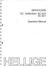
so that its light beam illuminates the infrareddetector. An opaque flag is mounted concentricallyto the camshaft and rotates with it betweenthe infrared light source and detector.When the flag interrupts the light beam, theoutput of the detector is sensed by the microprocessorvia an input port bit. Power to theinfrared LED light source is controlled by themotor drive circuit and is off when the motoris not running to conserve battery life.In the microprocessor software, multiplechecks are made on motion of the camshaft.When the motor is commanded to start, theinfrared sensor must show that half a revolutionhas occurred within four seconds and thatthe motor has stopped when half a rotationwas completed. In addition, no camshaftrotation can take place when the motor hasnot been commanded to run.Power CircuitryPower for the pump is normally supplied bytwo AA alkaline batteries, two AA lithiumbatteries, or an AC adapter. These types ofbatteries have a fairly low internal resistanceover their discharge range, which will keeppower supply noise low. Other types of batteries,such as carbon-zinc, exhibit high internalresistance, especially near depletion. A voltagedrop across the internal resistance occurs whencurrent is drawn by the motor during pumpactivations. This current is demanded in shortpulses when the motor is first turned on andgenerates large spikes in the battery voltage.This noise can cause the low battery detectioncircuit to shut down the pump.The power from the two AA batteries isboosted to +5VDC. This 5V is used to powerthe motor and a 3.3V linear regulator. Thelinear regulator provides power to all the othercircuitry including the microprocessor.Voltage Reference CircuitA voltage reference circuit provides a constantDC voltage to the microprocessor Analog toDigital Converter (ADC). By reading this inputand comparing the value to a predeterminedrange, the microprocessor can validate theaccuracy of the 3.3-volt power supply. Variationsin the 3.3-volt supply left undetected canresult in inaccuracy in the low battery alarmset points and variations in other calculatedvalues. (Also refer to Voltage Detector Circuitdescription on page 18.)<strong>Pump</strong>ing MechanismThe pumping mechanism is linear peristalticwith two active valves and an expulsor. <strong>Pump</strong>ingoccurs when the expulsor presses on thereservoir pump tubing in sequence with theinlet and outlet valves. At rest, the outlet valveis pressing down fully on the tubing and theexpulsor and inlet valve are retracted. (SeeFigure 9.)MotorCamshaft<strong>Pump</strong> HousingExpulsorOcclusion SensorCassette HingeLock Cassette<strong>Pump</strong> TubingUpstream SensorPressure PlateInlet ValveOutlet ValveFigure 9. A simulated pumping mechanism in a CADD-<strong>Legacy</strong> pump.14
When the microprocessor commands the mechanismto pump, the camshaft begins to rotate,thus controlling the following pump cycle:1. The inlet valve closes.2. In synchrony with the expulsor movingdown to compress the tubing, the outletvalve opens, expelling 0.050 ml of fluidtoward the patient.3. The outlet valve closes.4. The inlet valve opens as the expulsor isretracted, causing fluid from the reservoir toagain fill the pump tubing segment.5. The camshaft rotation stops after half arevolution and the cycle is completed.<strong>Pump</strong>ing CharacteristicsTo deliver the amount of drug specified by theparameter settings, the pump’s microprocessorcauses the pump mechanism to deliver fluid“pulses” timed according to the desired rate.At rates of 15 ml/hr or less the microprocessordelivers a single pulse to the motor circuitcausing a half revolution of the camshaft andfluid delivery in 0.05 ml increments. At ratesgreater than 15 ml/hr the microprocessordelivers two back to back pulses to the motorcircuit causing a full revolution of the camshaftand fluid delivery in 0.1 ml increments. Thus,to deliver 20 ml/hr, for example, the microprocessorsolves these equations:Mechanism activations per hr= 20 ml per hr/0.1 ml per activation= 20/0.1= 200Time (seconds) between activations= 3600 sec per hr/number of activations per hr= 3600/200=18NOTE:At rates 15 ml/hr the pump delivers 0.05ml per stroke. This allows a more continuousdelivery at low rates.The microprocessor uses its timer circuits toaccurately time the 18 seconds (in this example)between mechanism activations. Thetimebase accuracy is ultimately determined bythe 3.6864 MHz quartz crystal oscillator.Air DetectorThe air detector is designed to detect air in theoutlet tubing fluid path. The air detector can beset to On-high sensitivity, On-low sensitivity, orOff by accessing Biomed Functions. When theOn-high sensitivity setting is selected the pumpwill detect a single bubble greater than 0.100 ml.When the On-low sensitivity setting is selectedthe pump will detect a single bubble greater than0.250 ml.Multi-bubble SensingThe air detector is also designed to sense if anaccumulation of more than 1 ml of air haspassed through the outlet tubing path in the last15 minutes. This feature is active anytime the airdetector is on.The air detector is compatible with all of theMedication Cassette Reservoirs and CADD ®Administration Sets indicated for use with theCADD-<strong>Legacy</strong> pump, and all pump accessories.It is powered directly from the pump and noadditional power is required.Theory of OperationThe air detector consists of sensor electronics andtwo ultrasonic transducers positioned on oppositesides of the fluid path. One transducer acts asan acoustic transmitter and the other as anacoustic receiver. Air detection occurs when air inthe fluid path causes a reduction in the signallevel to the receiver. When the signal is interruptedfor a preset length of time, the sensingcircuitry sends a signal to the microprocessorindicating air in the fluid path. To maximize thereliability of the system and to reduce falsealarms, the transmitted signal is swept over afrequency range. This accommodates varyingresonance frequencies of the transducer andreduces sensitivity to tubing tolerances and othermechanical variations.15
VoltageTrip PointVoltageTrip PointSourceMotor StatusCADD-<strong>Legacy</strong> <strong>Pump</strong> Status2.4 VBatteryRunning/not runningNo alarm< 2.4 VBatteryNot runningAudible alarm (3 beeps every 5 minutes); Low Batmessage appears †< 1.8 VBatteryRunningAudible alarm (3 beeps every 5 minutes); Low Batmessage appears †< 4.75 V5 Volt supplymotor voltageRunningBattery Depleted message appears ††< 1.0 VBatteryRunning/not runningHardware reset occurs; <strong>Pump</strong> continues to indicatedepleted battery conditionTable 9. CADD-<strong>Legacy</strong> pump low battery conditions.Cassette Present Sensor CircuitThe cassette present sensor system consists of aswitch on the pump mechanism that interfacesto the attached cassette and associated circuitry.This switch senses the presence of acassette.When a cassette is latched to the pump, thecassette presses against the switch in the pumpmechanism. Electronic circuitry on the circuitboard detects this and reports the informationto the microprocessor. This system acts as asafety feature to detect a damaged or detachedcassette. If, during operation, the microprocessordetects the switch open, the pump willenable audible and visual alarms and stopdelivery.Redundancy with the upstream occlusionsensor prevents single fault failures fromcausing over or under delivery of fluid. Additionalcircuitry allows these sensors to beturned on and off by the microprocessor toconserve battery power.Voltage Detector CircuitLow voltage detection is performed by part ofthe watchdog circuit and by the microprocessorvia software. Three low voltage levels aredetected. The first two levels (Low Battery andBattery Depleted) are detected by software andthe third by hardware.The first level to be reached is the Low BatteryWarning threshold which occurs when thebattery voltage decays to a nominal value of2.4 volts when motor is off or 1.8 volts whenmotor is active. An Analog to Digital Converter(ADC) built into the microprocessorallows the microprocessor, via software, tomonitor the battery voltage and motor voltage.At the Low Battery Warning threshold, themicroprocessor enables a periodic series ofbeeps and displays a “Low Bat” warningmessage on the LCD.The second level is Battery Depleted Warningthreshold. As the voltage operating the motorreaches a nominal value of 4.75 volts, thesoftware disables delivery, places a “BatteryDepleted” message on the LCD, and enables acontinuous two tone audible alarm.The third level is a hardware reset which isreached when the battery voltage decays to anominal value of 1.0 volt. At this point ahardware reset circuit is triggered which placesthe microprocessor in reset. This preventsambiguous microprocessor operation as thebattery voltage continues to decay. The hardwarereset continues until the battery is completelydischarged or until it is removed. Ahardware reset can only be cleared by replacingthe old batteries with two fresh ones.†The pump emits 3 beeps every 5 minutes, and the message“Low Bat” appears on the pump’s display, indicating thatthe battery power is low, but the pump is operable.††The pump emits a continuous, variable-tone alarm, andthe message “Battery Depleted” appears on the display, thebattery power is too low to operate the pump and pumpoperation has stopped.18
Software Safety FeaturesHardware-related Software Safety FeaturesProgram Memory CheckAt power up and at regular intervals thereafter,the program memory is tested by calculating aCyclic Redundancy Code (CRC) on the programand then comparing it with the CRC stored withthe program. If the stored and calculated CRCsdo not match, the software will display a systemfault screen, turn on a continuous two-toneaudible alarm, and stop all drug delivery.RAM Memory CheckAt power up, the random access memory ischecked. A particular bit pattern is written toand read from each address in the RAM. If theread data is different from the written data, thesoftware will display a system fault screen, turnon a continuous two-tone audible alarm, andstop all drug delivery.Motor Circuit CheckAt power up and at regular intervals thereafter,the motor circuit is checked to ensure that nopower is being applied to the motor unless themotor is actually on. If the software detectspower being applied to the motor at any othertime, it will sound a continuous two-toneaudible alarm and will no longer attempt todeliver medication. During every pump activation,the software checks to see whether themotor completes one activation. If the motorfails to turn, or fails to complete a cycle, thesoftware will display a system fault screen, turnon a continuous two-tone audible alarm, andstop all drug delivery.Keypad Encoder CheckKey presses are routed to the microprocessor viaa keypad encoder. Every time the softwarereceives data from the keypad encoder, it ischecked. If the data is not a valid key press, thesoftware disregards it.The keypad contains a redundant switch in the⁄ key, ‹ key, and Í key (CADD-<strong>Legacy</strong> PCA). The redundant switch in each of thesekeys is routed to the microprocessor via an I/Ochip. The microprocessor must see a valid signalsimultaneously from the redundant switch andthe normal switch (routed through the keypadencoder) before it will start infusing.Data Handling Software Safety FeaturesData Stored in RAMBefore use, data associated with delivery andstored in RAM is tested by calculating a CRCon the data and then comparing it with theCRC stored with the data. If the stored andcalculated CRCs do not match, the softwarewill display a system fault screen, turn on acontinuous two-tone audible alarm, and stopall drug delivery.Data Stored in EEPROMBefore use, data associated with delivery andstored in EEPROM is tested by calculating aCRC on the data and then comparing it withthe CRC stored with the data. If the stored andcalculated CRCs do not match, the softwarewill display a system fault screen, turn on acontinuous two-tone audible alarm, and stopall drug delivery.Data Stored in NOVRAMBefore use, data associated with delivery andstored in NOVRAM is tested by calculating aCRC on the data and then comparing it withthe CRC stored with the data. If the stored andcalculated CRCs do not match, the softwarewill display a system fault screen, turn on acontinuous two-tone audible alarm, and stopall drug delivery.Data Used in CalculationsCalculations on data used in some way tocontrol the delivery of drug are performedredundantly. The two calculated values arethen compared. If the two values do not match,the software will display a system fault screen,turn on a continuous two-tone audible alarm,and stop all drug delivery.Timer Data RegistersThe data in the timer Real Time Clock ischecked at regular intervals. If the data is notreasonable, the software will turn on a continuoustwo-tone audible alarm and stop alldrug delivery.19
7 Hardware and SoftwareFault DetectionOverviewIf the CADD-<strong>Legacy</strong> pump displays an errorcode, a hardware or software fault has beendetected by the microprocessor, and the pumpshould be returned for servicing.When hardware or software faults are detectedby the microprocessor, pump operation stopsand a continuous two-tone audible alarm willbe activated. An error message will be displayedon the LCD. On the next power up, theerror code will again be displayed. If the errordetected was a data fault, the pump will be inLock Level 2, and all other programmedfunctions will have default values. (See thepump’s Operator’s <strong>Manual</strong> for specific defaults.)Order of Error Code Events1. There is a continuous two-tone audiblealarm and the display will readError Code DescriptionRange1010-1040 Software Application Errors1110-1160 Software Control Errors1210-1270 CRC Errors1310-1340 Real Time Clock Errors1410-1450 Standard Delivery CalculationErrors1510-1530 Air Detector System Errors1610-1670 CPU Test Errors1710-1720 Miscellaneous HardwareErrors1810-1872 Motor ErrorsTable 10. CADD-<strong>Legacy</strong> pump error codes.Error DetectedE(XXXX)NOTE:“XXXX” is a 4-digit code.2. To silence the error code alarm, remove thebatteries.3. At each subsequent power up the pump willdisplay the initial power up screen and thenthe following screen:LEC XXXXThus there is always a display of the “LastError Code (LEC)” detected by the microprocessor.20
8 Cleaning and InspectionProceduresInspection RecommendationDeltec recommends annual functional inspectionon the CADD-<strong>Legacy</strong> 1, CADD-<strong>Legacy</strong> PLUS, and CADD-<strong>Legacy</strong> PCA pumps. Thefollowing inspection procedures should beperformed annually to verify function andaccuracy.NOTE:Persons performing the following tests andprocedures should be familiar with theDeltec CADD-<strong>Legacy</strong> pump. Please readthe Operator’s <strong>Manual</strong> supplied with thepump before proceeding.WARNING:CADD-<strong>Legacy</strong> pumps are sealed units. Abroken or damaged seal will, therefore, beconsidered conclusive evidence that thepump has been misused and/or altered,which voids any and all warranties. Allservice and repair of CADD-<strong>Legacy</strong> pumpsmust be performed by Deltec or its authorizedagents.CleaningUse any of the following solutions to clean thepump and accessories:• Soap solution• Benzalkonium chloride concentrate (0.13%)• Glutaral concentrate, USP (2%)• 10 percent solution of household bleach (onepart household bleach to nine parts water)• Alcohol, USP (93%)• Isopropyl Alcohol, USP (99%)• PDI - Super Sani-Cloth ®• Mada Medical - MadaCide• 70% Chlorohexine1. Dampen a soft, lint-free cloth with cleaningsolution. Apply the solution to exteriorsurface of the pump or accessory. Do notallow the solution to soak into the pump oraccessory.2. Wipe the entire surface dry with anothersoft, lint-free cloth. Allow the pump to drycompletely before use.CAUTION:• Do not immerse the pump in cleaning fluidor water. Do not allow solution to soak intothe pump, accumulate on the keypad, orenter the battery compart-ment. Moisturebuild-up inside the pump may damage thepump.• Do not clean the pump with acetone, otherplastic solvents, or abrasive cleaners, asdamage to the pump may occur.Battery Contact Cleaning<strong>Pump</strong> battery contact cleaning can be performedeasily using a clean cotton swab wettedwith Isopropyl Alcohol or by using a premoistenedAlcohol swab. Use a minimum of70% concentration by volume IsopropylAlcohol. Do not use Alcohol formulation thathas other additives besides Alcohol and water.• Using a cotton swab wetted with Alcohol orthe pre-moistened Alcohol swab, rub withmedium pressure over the entire contactsurface a minimum of ten back and forthcycles (twenty total wipes over the contact).• Select a fresh surface of the swab and repeatthe cleaning process on the second batterycontact. Dispose of the swab when finished.• Using a second Alcohol wetted swab, rubover each contact surface again a minimumof four back and forth cycles (eight totalwipes over the contact). Allow the contactsto dry for a few minutes.21
Visual Inspection• Visually inspect the pump for any damage tothe LCD, occlusion sensor seals, valves andexpulsor, cassette hinge area, cassette lock,cassette sensor, keypad, indicator light,power jack, accessory jack, air detector, andhousing. If any damage is noted, the pumpshould be returned for service.• Check the battery door for proper operation.It should not be broken or damaged. Thebattery door mating tabs on the pumphousing should not be broken or damaged.• Examine the battery compartment fordamage. If the battery contacts appearcorroded, clean them as instructed on page20. If the battery contacts appear to be bentor pushed in, straightening may be possiblewith a small screwdriver or other suitabletool. Care must be taken not to damage thepump housing or to incur further damage tothe contacts.Mechanical Inspection• Press each key on the keypad. Each keyshould have a distinctive dome feeling. Thekeys should not feel flat.• Attach the battery door. The battery doorshould fit snugly in place when it is closed onthe pump.• Attach either a 50-ml or 100-ml MedicationCassette Reservoir or a CADD ® AdministrationSet to the pump. Using a coin (keyfor the CADD-<strong>Legacy</strong> PCA pump), turn thelock 1/4 turn counter-clockwise. Check forsmooth operation and a definite feel whenthe lock pulls the cassette firmly against thebottom of the pump. The slot on the cassettelock should be aligned with the “LOCKED”indicator on the side of the pump.• Gently twist and pull on the cassette to makesure it is firmly attached.22
9 Testing ProceduresTesting RecommendationDeltec recommends annual functional testingon the CADD-<strong>Legacy</strong> pumps. The followingtesting procedures should be performed annuallyto verify function and accuracy.NOTE:To perform the following functional teststhe pump must be in Lock Level 0.Changing to Lock Level 0 (LL0)Before programming the pump, make sure thelock level is 0. LL0 allows the operator toaccess all programming and operating functions.1. Make sure the pump is stopped. Press Œ.The current lock level will appear. (If thelock level is already LL0, press „ to exit.)2. Press ´ or Î until “LL0” appears.3. Press Œ again or ¤. “Code 0” willappear.4. Press ´ or Î until the Lock Level Code“63” appears for CADD-<strong>Legacy</strong> PCA,“64” for CADD-<strong>Legacy</strong> 1 or “65” forCADD-<strong>Legacy</strong> PLUS.5. Press Œ or ¤ to set the new lock level.CADD-<strong>Legacy</strong> PCA <strong>Pump</strong>Power-up Check• Insert batteries or press Å and observe theLCD during power up. The first screen willdisplay the serial number, model number,and software number with revision level.The second screen will display 32 characterblocks. (If “LEC” and four digits appearprior to the pump displaying the 32 characterblocks, the pump has experienced anelectrical or mechanical fault and should bereturned for service.) If no error message isimmediately shown, the pump has poweredup normally. The pump will then sequentiallydisplay all of the programmed valuesand beep at each screen. After all screens aredisplayed, successful power up is indicatedwith six audible beeps and the “STOPPED”screen displayed. Continue with the Lockcheck.To Access Biomed Functions Loop1. Press Œ. The current lock level willappear.2. Press Œ or ¤. “CODE 0” will appear.3. Press ´ or Î until the Biomed functioncode “163” appears (Lock Code +100).Then press Œ or ¤.Air Detector ON/OFF1. Press „ until “Air Detector” appears.2. Use ´ or Î to select “Off.”3. Press ¤ to enter the change.Lock Check• Attach a 50- or 100-ml Medication Cassette Reservoir or a CADD ® AdministrationSet to the pump. The mark on theCassette Lock button should be aligned withthe “Locked” symbol.Cassette Sensor Check• Unlock the cassette by inserting a key intothe lock and turning clockwise.• The pump should issue an audible alarm andthe display should read “No DisposableClamp Tubing”.• Press ⁄ or „ to silence the alarm. Pressand hold Å to turn the pump off.The following three checks (LCD, Motorand Gear Train, and Reservoir VolumeEmpty Alarm Check) should be performedin the sequence shown.LCD Check• With the pump turned off, press Å. Thesecond screen that the pump displays willconsist of 32 blocks of characters. Examinethe LCD to verify that there are no missingdark pixels in the character blocks.23
Testing Procedures - CADD-<strong>Legacy</strong> PCA pump continuedMotor and Gear Train Check• Program the Reservoir Volume to 2.0 ml.• Attach either a 50- or 100-ml MedicationCassette Reservoir or CADD ® AdministrationSet to the pump. Lock the cassette.• Press and hold ‹ until three series ofdashes appear. Release ‹. Press and hold‹. While priming the pump, listen to themotor for excessive noise or grindingsounds. Count the number of pump activations.The pump should prime ten doubleactivations and then stop. Press „ toreturn to main menu.Reservoir Volume Empty Alarm Check• Program the Reservoir Volume to 1.0 ml.Press „ until Reservoir Volume is displayedon the LCD. Press ´ or Î until1.0 ml is displayed. Then press ¤.• Press and hold ‹ until three series ofdashes appear. Release ‹. Press and hold‹. The pump should prime ten doubleactivations and then stop. The pump willalarm and display “Reservoir VolumeEmpty.” Press „.Starting/Stopping the <strong>Pump</strong>• Program the pump with the followingvalues:Reservoir Volume: 1.0 mlUnits: millilitersContinuous Rate: 50 ml/hrDemand Dose: 0.00 mlGiven: 0.00 (Press ¤)• Program the Air Detector Off.• Press and hold ⁄. “Starting” appearsfollowed by three sets of dashes, each accompaniedby a beep. A review of theprogrammed parameters then appears. Themain screen should appear with “RUN” inthe display.• To stop the device, press and hold ⁄.“Stopping” appears followed by three sets ofdashes that disappear one at a time, eachaccompanied by a beep. The main screenshould appear with “STOPPED” in thedisplay.24Activation Timing Check• Reprogram the Reservoir Volume to 1.0 andclear the Given screen.• Press and hold ⁄ until three dashesdisappear from the display. The pumpshould sequentially display all of the programmedvalues. Start a timer at the firstmotor activation.• Count the activations. One activation shouldoccur every six seconds. Approximatelysixty-six seconds and ten activations later,the Reservoir Volume alarm should occur.The display should show “Reservoir VolumeEmpty.”DOSE Key Check(CADD-<strong>Legacy</strong> PCA pump only)• Check the Í key operation by programmingthe pump with the following values:Reservoir Volume: 10.0 mlUnits:MillilitersContinuous Rate: 0.0 ml/hrDemand Dose: 1.00 mlDose Lockout: 00 hrs 5 minDoses Per Hour: 12Doses Given: 0 doses (Press¤ to clear)Doses Attempted: 0 doses (Press¤ to clear)Given:0.00 ml (Press¤ to clear)• Press and hold ⁄. The pump shouldsequentially display all of the programmedvalues.• After “RUN” appears on the display, pressÍ and note the time. The pump shouldbeep twice and begin to deliver. Count thenumber of pump activations. The pumpshould make ten double activations. Afterten double activations, the display shouldshow a Reservoir Volume of 9.0 ml. PressÍ two more times within the next 5minutes. The pump should not deliver.Remote Dose Cord Check(CADD-<strong>Legacy</strong> PCA pump only)• Wait 5 minutes after the dose given above;then, instead of pressing Í, press thebutton on the Remote Dose Cord. The pumpshould make ten double activations. Afterten double activations, the display shouldshow a Reservoir Volume of 8.0 ml. Press
Testing Procedures - CADD-<strong>Legacy</strong> PCA pump continuedthe Remote Dose Cord button two moretimes within the next 5 minutes. The pumpshould not deliver.Doses Given and Doses Attempted Check(CADD-<strong>Legacy</strong> PCA pump only)• Stop the pump by pressing and holding ⁄.Use „ to advance to the Doses Givenscreen. The screen should show 2. Use „to advance to the Doses Attempted screen.The display should show 6. (If the abovesteps have not been followed exactly, differentvalues may appear.)GIVEN Mode Check• Press „ to advance to the Given screen.The display should now show2.00 ml. (If the above steps have not beenfollowed exactly, a different value mayappear.)• Press the ¤ key. The display should nowshow 0.00 ml.Air Detector TestThis test will verify the function of the airdetector. To perform this test, the air detectormust be turned on. The previous program fromthe Í key check can be used to perform thistest.• Attach an empty Medication Cassette Reservoir or CADD ® Administration Set tothe pump.• Secure it using the lock button.• Thread the tubing through the air detectorgroove.• Start the pump.• The pump should respond with a continuoustwo-tone alarm and the display should read:“Air In Line Detected”• Press „ or ⁄ to silence the alarm, andremove the Medication Cassette Reservoiror CADD ® Administration Set.• Now attach a Medication Cassette Reservoircontaining fluid, or a primed CADD ®Administration Set to the pump. Makecertain there is no air in the fluid path.• Secure it using the lock button.• Thread the tubing through the air detectorgroove.• Start the pump.• Deliver a demand dose. (NOTE: Five minutesmust have passed since the delivery ofthe last demand dose.)• The pump should deliver the dose withoutan air detection alarm.Upstream Occlusion Sensor Test• Verify that the Upstream Occlusion Sensor isturned on. (See page 23, To Access BiomedFunctions Loop.)• Obtain a CADD ® Administration Set withbag spike and anti-siphon valve. Also obtaina clamp (slide clamp or hemostat).• Insert the CADD ® Administration Set spikeinto an appropriate, standard IV bag filledwith water. Attach the cassette to the pump.Prime the entire fluid path.• Program the pump to deliver a continuousmaximum rate. Press and hold ⁄ to startthe pump.• Clamp the tubing halfway between the IVbag and the pump. The pump should alarmwithin three activations after clamping thetubing.Occlusion Pressure Range TestsOcclusion Pressure Range Test IDescriptionPressure is generated by activating the pumpingmechanism with an attached filled,clamped Medication Cassette Reservoir. Thepump is started and a Demand Dose is givenuntil the high pressure alarm sounds.Equipment needed50- or 100-ml Medication Cassette Reservoircontaining distilled waterProcedure1. Insert two AA batteries and wait for thepump to power up.2. Attach a Medication Cassette Reservoircontaining water to the pump. Lock thecassette.25
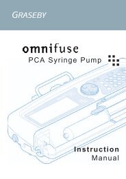
Testing Procedures - CADD-<strong>Legacy</strong> PCA pump continued3. Prime the Medication Cassette Reservoirtubing. The tubing should be filled withfluid to the end of the luer lock connector.The system must be free from air bubblesfor this test.4. Close the slide clamp on the distal end ofthe tubing near the female luer of theMedication Cassette Reservoir.5. Program the pump to the following parameters:Reservoir Volume: 10.0 mlUnits:MillilitersContinuous Rate: 0.00 ml/hrDemand Dose: 1.00 mlDose Lockout: 00 hrs 5 minDoses Per Hour: 12Dose Given:0 (Press ¤ toDose Attempts:clear)0 (Press ¤ toclear)Milligrams Given: 0.00 ml (Press ¤to clear)6. Start the pump. When the pump is running,activate a Demand Dose, noting when thehigh pressure alarm is activated.7. The pump should alarm when the pumpdelivers between 1 and 2 activations.Occlusion Pressure Range Test IIDescriptionAn adjustable metered pressure source isconnected to the Medication Cassette Reservoirtubing. The pressure is slowly increaseduntil the high pressure alarm sounds.Equipment needed• Pressure gauge, 40 psi ± 1 psi (2.76 bar ± 0.07bar)• Pressure vessel, partially filled with water• Pressure regulator, 40 psi (2.76 bar ± 0.07 bar)• 50 or 100 ml Medication Cassette Reservoircontaining waterCAUTION:At the completion of the test, the pressure must bereduced to zero before detaching the cassette fromthe pump; otherwise, the cassette may rupture.Safety glasses should be worn while conducting orobserving this test.Procedure1. Insert two AA batteries and wait for the pumpto power up.2. Attach a Medication Cassette Reservoir to thepump. Lock the cassette.NOTE:The pressure from the source must be zerowhen the cassette is attached.3. Assemble the apparatus as shown in Figure 11.4. Connect the Medication Cassette Reservoiroutlet tube to the metered pressure source.NOTE:Do not use a CADD ® Extension Set withAnti-siphon Valve.5. Program the pump for a continuous rate of50 ml/hr. Press ⁄.6. Slowly increase the back pressure, notingwhen the high pressure alarm is activated.1998-11-22 D. Zurn«Lgc Occlusion Setup»40PSIRegulatorPressure GaugeNOTE:The pressure may be increased rapidly to 8 psi(0.55 bar), after which the pressure should beincreased at 3 psi/min (0.21 bar/min) or lessuntil the alarm sounds.7. The high pressure alarm should sound within1.79 (±0.97) bar, or 26 (±14) psi.Figure 11. Occlusion test set-up.26
Testing Procedures - CADD-<strong>Legacy</strong> PCA pump continuedAccuracy TestingGravimetric Accuracy TestingDescriptionA Medication Cassette Reservoir is partiallyfilled with water and weighed. The cassette isthen attached to the pump and the pump is setto deliver a certain amount of water. Thecassette is then removed and weighed again.The amount of water delivered is compared tothe amount that the pump should have delivered.Nominal system accuracy is given in the technicalspecifications section for the pump. That is,under the test conditions described below, theaccuracy of the pump and Medication Cassette Reservoir will be nominal with a 90% confidencelevel. The nominal test conditions are asfollows: degassed water at 25 ± 5°C withoutback pressure.Equipment needed• 50- or 100-ml Medication Cassette Reservoir• 50 or 60 ml syringe• CADD ® Extension Set with Anti-siphon Valve• A balance accurate to 0.1 g• 40 ml of room temperature waterProcedure1. Fill the 50 or 60 ml syringe with 40 ml ofwater. Transfer the water into aMedication Cassette Reservoir.2. Remove any air from the Medication Cassette Reservoir by aspirating the air withthe syringe. Attach the CADD ® ExtensionSet with Anti-siphon Valve. Prime the tubingso it is filled with fluid to the end of theCADD ® Extension Set luer lock connector.3. Weigh the entire Medication Cassette Reservoir/CADD ® Extension Set assemblyand record the weight. This is the predeliveryweight. (This weight includes theempty Medication Cassette Reservoir,CADD ® Extension Set, and weight of thewater.)4. Attach the Medication Cassette Reservoir tothe pump. Program the reservoir volume to20 ml. Now press ¤. This value is theintended delivery volume. Remove the slideclamp.5. With the pump in Lock Level 0, program acontinuous rate of 50 ml/hr. Start the pumpand deliver 20 ml.6. Again, secure the slide clamp as close aspossible to end of the CADD ® Extension Setluer lock connector. Remove the MedicationCassette Reservoir from the pump andweigh the entire Medication Cassette Reservoir/CADD ® Extension Set assembly.This is the post-delivery weight.7. Calculate the difference in weight betweenthe pre-delivery weight and the post-deliveryweight. This is the weight of the amountdelivered. (1 ml of water at 20° weighs 1gram.)8. Find the difference between the volume ofthe amount delivered and the intendeddelivery volume. This is the inaccuracyvolume.9. Divide the inaccuracy volume by the intendeddelivery volume and multiply by 100.This is the accuracy error percentage. (SeeTable 11.)10.If the accuracy error percentage is greaterthan ± 6%, repeat the test with a new MedicationCassette Reservoir. If the pump failsa second time, call Deltec’s Customer <strong>Service</strong>Department.Pre- Post- Weight of Intended Inaccuracy Accuracy AccuracyDelivery Delivery Amount Delivery Volume Error Error PercentageWeight Weight Delivered Volume61.1 g 41.6 g 19.5 g = 19.5 ml 20 ml -0.5 ml -0.5 ml ÷ 20.0 ml = -0.025 x 100 = -2.5%-0.025Table 11. Gravimetric percentage calculation27
Testing Procedures - CADD-<strong>Legacy</strong> PCA pump continuedExample:• 40 ml of room temperature waterPre-delivery Weight:61.1 gNOTE:Post-delivery Weight: – 41.6 gThe test procedure calls for the use of aWeight of Amount Delivered: 19.5 g= 19.5 mlMedication Cassette Reservoir and aCADD ® Extension Set with Anti-siphonValve. An IV bag and CADD ® AdministrationSet with integral or add-on anti-Volume of Amount Delivered: 19.5 mlIntended Delivery Volume: – 20.0 mlsiphon valve can be substituted for theInaccuracy Volume:-0.5 mlMedication Cassette Reservoir andCADD ® Extension Set with Anti-siphonInaccuracy Volume:-0.5 mlValve.Intended Delivery Volume: ÷ 20.0 mlAccuracy Error: -0.025x 100.00Procedure:1. Fill the 50- or 60-ml syringe with 40 ml ofAccuracy Error Percentage = -2.5%water. Transfer the water into aMedication Cassette Reservoir.Volumetric Accuracy Testing2. Remove any air from the MedicationCassette Reservoir by aspirating the airDescription:with the syringe. Attach the CADD ® ExtensionSet with Anti-siphon Valve. Prime theA predetermined amount of water is deliveredinto a collection device such as a burette ortubing so it is filled with fluid to the end ofgraduated cylinder. The amount of waterthe CADD ® Extension Set luer lock connector.delivered is compared to the amount that thepump should have delivered.Nominal system accuracy is given in thetechnical specifications section for the pump.That is, under the test conditions describedbelow, the accuracy of the pump and Medication3. Insert the end of the CADD ® Extension Setinto the fluid collection device.4. Attach the Medication Cassette Reservoirto the pump. Program the Reservoir Volumeto 20 ml. This is the intended deliveryCassette Reservoir will be nominal withvolume. Remove all clamps.a 90% confidence level. The nominal test5. Program a continuous rate of 50 ml/hr.conditions are as follows: degassed water at 25Start the pump and deliver 20 ml.± 5°C without back pressure.6. When delivery is complete, record theEquipment needed:• 50- or 100- ml Medication Cassette Reservoirvolume of fluid delivered. This is the actualdelivery.7. Find the difference between the volume of• 50- or 60- ml syringethe amount delivered and the intendeddelivery volume. This is the inaccuracy• CADD ® Extension Set with Anti-siphonvolume.Valve8. Divide the inaccuracy volume by the intendeddelivery volume and multiply by• A fluid collection device such as a burette ora class A 25 ml capacity graduated cylinder100. This is the accuracy error percentage.(See Table 12.)Intended Actual Inaccuracy Accuracy AccuracyDelivery Delivery Volume Error Error PercentageVolume Volume20 ml 19.5 ml -0.5 ml -0.5 ml ÷ 20.0 ml = -0.025 -0.025 x 100 = -2.5%Table 12. Volumetric percentage calculation28
9. If the accuracy error percentage is greaterthan ± 6%, repeat the test with a newMedication Cassette Reservoir. If thepump fails a second time, call Deltec’sCustomer <strong>Service</strong> Department.Example:Actual Delivery Volume: 19.5 mlIntended Delivery Volume: – 20.0 mlInaccuracy Volume:= -0.5 mlInaccuracy Volume:-0.5 mlIntended Delivery Volume: ÷ 20.0 mlAccuracy Error: -0.025x 100.00Accuracy Error Percentage: = -2.5%CADD-<strong>Legacy</strong> 1 <strong>Pump</strong>Power-up Check• Insert batteries or press Å and observe theLCD during power up. The first screen willdisplay the serial number, model number,and software number with revision level.The second screen will display 32 characterblocks. (If “LEC” and four digits appearprior to the pump displaying the 32 characterblocks, the pump has experienced anelectrical or mechanical fault and should bereturned for service.) If no error message isimmediately shown, the pump has poweredup normally. The pump will then sequentiallydisplay all of the programmed valuesand beep at each screen. After all screens aredisplayed, successful power up is indicatedwith six audible beeps and the “STOPPED”screen displayed. Continue with the Lockcheck.To Access Biomed Functions Loop1. Press Œ. The current lock level willappear.2. Press Œ or ¤. “CODE 0” will appear.3. Press ´ or Î until the Biomed functioncode “164” appears (Lock Code +100).Then press Œ or ¤.Air Detector ON/OFF1. Press „ until “Air Detector” appears.2. Use ´ or Î to select “Off.”3. Press ¤ to enter the change.Lock Check• Attach a 50- or 100-ml Medication Cassette Reservoir or a CADD ® AdministrationSet to the pump. The slot on the CassetteLock button should be aligned with the“Locked” symbol.Cassette Sensor Check• Unlock the cassette by inserting a coin intothe latch and turning clockwise.• The pump should issue an audible alarm andthe display should read “No DisposableClamp Tubing”.• Press ⁄ or „ to silence the alarm. Pressand hold Å to turn the pump off.The following three checks (LCD, Motorand Gear Train, and Reservoir VolumeEmpty Alarm Check) should be performedin the sequence shown.LCD Check• With the pump turned off, press Å. Thesecond screen that the pump displays willconsist of 32 blocks of characters. Examinethe LCD to verify that there are no missingdark pixels in the character blocks.Motor and Gear Train Check• Program the Lock Level to LL0. Program theReservoir Volume to 2.0 ml.• Attach either a 50- or 100-ml MedicationCassette Reservoir or CADD ® AdministrationSet to the pump. Lock the cassette.• Press and hold ‹ until three series ofdashes appear. Release ‹. Press and hold‹. While priming the pump, listen to themotor for excessive noise or grindingsounds. Count the number of pump activations.The pump should prime ten doubleactivations and then stop. Press „ toreturn to the main menu.Reservoir Volume Empty Alarm Check• Program the Reservoir Volume to 1.0 ml.• Press and hold ‹ until three series ofdashes appear. Release ‹. Press and hold‹. The pump should prime ten doubleactivations and then stop. The pump willalarm and display “Reservoir VolumeEmpty.” Press „.29
Testing Procedures - CADD-<strong>Legacy</strong> 1 pump continuedStarting/Stopping the <strong>Pump</strong>• Program the pump with the followingvalues:Reservoir Volume: 1.0 mlRate:3000 ml/24hrsGiven: 0.0 ml (press ¤to clear)• Program the Air Detector Off.• Press and hold ⁄. “Starting” appearsfollowed by three sets of dashes, each accompaniedby a beep. A review of theprogrammed parameters then appears. Themain screen should appear with “RUN” inthe display.• To stop the device, press and hold ⁄.“Stopping” appears followed by three sets ofdashes that disappear one at a time, eachaccompanied by a beep. The main screenshould appear with “STOPPED” in thedisplay.Activation Timing Check• Reprogram the Reservoir Volume to 1.0 andclear the Given screen.• Press and hold ⁄ until three dashesdisappear from the display. The pumpshould sequentially display all of the programmedvalues. Start a timer at the firstmotor activation.• Count the activations. One activation shouldoccur every three seconds. Approximatelytwenty-seven seconds and ten activationslater, the Reservoir Volume alarm shouldoccur. The display should show “ReservoirVolume Empty.”GIVEN Mode Check• Press „ to advance to the Given screen.The display should now show 1.00 ml. (Ifthe above steps have not been followedexactly, a different value may appear.)• Press the ¤ key. The display should nowshow 0.00 ml.Air Detector TestThis test will verify the function of the airdetector. To perform this test, the air detectormust be turned on. The previous program fromthe Activation Timing Check can be used toperform this test.30• Attach an empty Medication Cassette Reservoir or CADD ® Administration Set tothe pump.• Secure it using the lock button.• Thread the tubing through the air detectorgroove.• Start the pump.• The pump should respond with a continuoustwo-tone alarm and the display should read:“Air In Line Detected”• Press „ or ⁄ to silence the alarm, andremove the Medication Cassette Reservoiror CADD ® Administration Set.• Now attach a Medication Cassette Reservoircontaining fluid or a primed CADD ®Administration Set to the pump. Makecertain there is no air in the fluid path.• Secure it using the lock button.• Thread the tubing through the air detectorgroove.• Program the Reservoir Volume to 1.0 ml.Start the pump.• The pump should deliver without an airdetection alarm.Upstream Occlusion Sensor Test• Verify that the Upstream Occlusion Sensor isturned on. (See page 29, To Access BiomedFunctions Loop.)• Obtain a CADD ® Administration Set withbag spike and anti-siphon valve. Also obtaina clamp (slide clamp or hemostat).• Insert the CADD ® Administration Set spikeinto an appropriate, standard IV bag filledwith water. Attach the cassette to the pump.Prime the entire fluid path.• Program the pump to deliver a continuousmaximum rate. Press and hold ⁄ to startthe pump.• Clamp the tubing halfway between the IVbag and the pump. The pump should alarmwithin three activations after clamping thetubing.
Testing Procedures - CADD-<strong>Legacy</strong> 1 pump continuedOcclusion Pressure Range TestsOcclusion Pressure Range Test IDescriptionPressure is generated by activating the pumpingmechanism with an attached filled,clamped Medication Cassette Reservoir. Thepump is started and a Demand Dose is givenuntil the high pressure alarm sounds.Equipment needed50- or 100-ml Medication Cassette Reservoircontaining distilled water.Procedure1. Insert two AA batteries and wait for thepump to power up.2. Attach a Medication Cassette Reservoircontaining water to the pump. Lock thecassette.3. Prime the Medication Cassette Reservoirtubing. The tubing should be filled withfluid to the end of the luer lock connector.The system must be free from air bubblesfor this test.4. Close the slide clamp on the distal end ofthe tubing near the female luer of theMedication Cassette Reservoir.5. Program the pump to the following parameters:Reservoir Volume: 10.0 mlContinuous Rate: 3000.0 ml/24hrGiven:0.0 ml (Press ¤ toclear)6. Start the pump. When the pump is running,note when the high pressure alarm is activated.1998-11-22 D. Zurn«Lgc Occlusion Setup»40PSIRegulatorFigure 12 . Occlusion test set-up.Pressure Gauge7. The pump should alarm when the pumpdelivers between 1 and 2 activations.Occlusion Pressure Range Test IIDescriptionAn adjustable metered pressure source isconnected to the Medication Cassette Reservoirtubing. The pressure is slowly increaseduntil the high pressure alarm sounds.Equipment needed• Pressure gauge, 40 psi ± 1 psi (2.76 bar ±0.07 bar).• Pressure vessel, partially filled with water.• Pressure regulator, 40 psi (2.76 bar ± 0.07bar).• 50 or 100 ml Medication Cassette Reservoircontaining water.CAUTION:At the completion of the test, the pressure must bereduced to zero before detaching the cassette fromthe pump; otherwise, the cassette may rupture.Safety glasses should be worn while conducting orobserving this test.Procedure1. Insert two AA batteries and wait for thepump to power up.2. Attach a Medication Cassette Reservoir tothe pump. Lock the cassette.NOTE:The pressure from the source must be zerowhen the cassette is attached.3. Assemble the apparatus as shown in Figure12.4. Connect the Medication Cassette Reservoiroutlet tube to the metered pressuresource.NOTE:Do not use a CADD ® Extension Set withAnti-siphon Valve.5. Program the pump for a continuous rate of3000 ml/24hr. Press ⁄.6. Slowly increase the back pressure, notingwhen the high pressure alarm is activated.31
Testing Procedures - CADD-<strong>Legacy</strong> 1 pump continuedNOTE:The pressure may be increased rapidly to 8psi (0.55 bar), after which the pressureshould be increased at 3 psi/min (0.21 bar/min) or less until the alarm sounds.7. The high pressure alarm should soundwithin 1.79 (±0.97) bar, or 26 (±14) psi.Accuracy TestingGravimetric Accuracy TestingDescriptionA Medication Cassette Reservoir is partiallyfilled with water and weighed. The cassette isthen attached to the pump and the pump is setto deliver a certain amount of water. Thecassette is then removed and weighed again.The amount of water delivered is compared tothe amount that the pump should have delivered.Nominal system accuracy is given in thetechnical specifications section for the pump.That is, under the test conditions describedbelow, the accuracy of the pump and MedicationCassette Reservoir will be nominal witha 90% confidence level. The nominal testconditions are as follows: degassed water at 25± 5°C without back pressure.Equipment needed• 50- or 100-ml Medication Cassette Reservoir• 50 or 60 ml syringe• CADD ® Extension Set with Anti-siphonValve• A balance accurate to 0.1 g• 40 ml of room temperature waterProcedure1. Fill the 50 or 60 ml syringe with 40 ml ofwater. Transfer the water into a MedicationCassette Reservoir.2. Remove any air from the MedicationCassette Reservoir by aspirating the airwith the syringe. Attach the CADD ® ExtensionSet with Anti-siphon Valve. Prime thetubing so it is filled with fluid to the end ofthe CADD ® Extension Set luer lock connector.3. Weigh the entire Medication Cassette Reservoir/CADD ® Extension Set assemblyand record the weight. This is the predeliveryweight. (This weight includes theempty Medication Cassette Reservoir,CADD ® Extension Set, and weight of thewater.)4. Attach the Medication Cassette Reservoirto the pump. Program the reservoir volumeto 20 ml. Now press ¤. This value is theintended delivery volume. Remove the slideclamp.5. With the pump in Lock Level 0, program acontinuous rate of 3000 ml/24hr. Start thepump and deliver 20 ml.6. Again, secure the slide clamp as close aspossible to end of the CADD ® Extension Setluer lock connector. Remove the MedicationCassette Reservoir from the pump andweigh the entire Medication Cassette Reservoir/CADD ® Extension Set assembly.This is the post-delivery weight.7. Calculate the difference in weight betweenthe pre-delivery weight and the post-deliveryweight. This is the weight of the amountdelivered. (One ml of water at 20°C weighs1 gram.)8. Find the difference between the volume ofthe amount delivered and the intendeddelivery volume. This is the inaccuracyvolume.Pre- Post- Weight of Intended Inaccuracy Accuracy AccuracyDelivery Delivery Amount Delivery Volume Error Error PercentageWeight Weight Delivered Volume61.1 g 41.6 g 19.5 g = 19.5 ml 20 ml -0.5 ml -0.5 ml ÷ 20.0 ml = -0.025 x 100 = -2.5%-0.025Table 13. Gravimetric percentage calculation32
Testing Procedures - CADD-<strong>Legacy</strong> 1 pump continued9.Divide the inaccuracy volume by the intendeddelivery volume and multiply by100. This is the accuracy error percentage.(See Table 13.)10.If the accuracy error percentage is greaterthan ± 6%, repeat the test with a newMedication Cassette Reservoir. If thepump fails a second time, call Deltec’sCustomer <strong>Service</strong> Department.Example:Pre-delivery Weight:Post-delivery Weight:Weight of Amount Delivered:Volume of Amount Delivered:Intended Delivery Volume:Inaccuracy Volume:61.1 g– 41.6 g19.5 g= 19.5 ml19.5 ml– 20.0 ml= -0.5 mlInaccuracy Volume:-0.5 mlIntended Delivery Volume: ÷ 20.0 mlAccuracy Error: -0.025x 100.00Accuracy Error Percentage: = -2.5%Volumetric Accuracy TestingDescription:A predetermined amount of water is deliveredinto a collection device such as a burette orgraduated cylinder. The amount of waterdelivered is compared to the amount that thepump should have delivered.Nominal system accuracy is given in thetechnical specifications section for the pump.That is, under the test conditions describedbelow, the accuracy of the pump and MedicationCassette Reservoir will be nominal witha 90% confidence level. The nominal testconditions are as follows: degassed water at 25± 5°C without back pressure.Equipment needed:• 50- or 100- ml Medication Cassette Reservoir• 50- or 60- ml syringe• CADD ® Extension Set with Anti-siphonValve• A fluid collection device such as a burette ora class A 25 ml capacity graduated cylinder• 40 ml of room temperature waterNOTE:The test procedure calls for the use of aMedication Cassette Reservoir and aCADD ® Extension Set with Anti-siphonValve. An IV bag and CADD ® AdministrationSet with integral or add-on antisiphonvalve can be substituted for theMedication Cassette Reservoir andCADD ® Extension Set with Anti-siphonValve.Procedure:1. Fill the 50- or 60-ml syringe with 40 ml ofwater. Transfer the water into aMedication Cassette Reservoir.2. Remove any air from the MedicationCassette Reservoir by aspirating the airwith the syringe. Attach the CADD ® ExtensionSet with Anti-siphon Valve. Prime thetubing so it is filled with fluid to the endof the CADD ® Extension Set luer lockconnector.3. Insert the end of the CADD ® Extension Setinto the fluid collection device.4. Attach the Medication Cassette Reservoirto the pump. Program the Reservoir Volumeto 20 ml. This is the intended deliveryvolume. Remove all clamps.5. Program a continuous rate of 3000 ml/24hr.Start the pump and deliver 20 ml.6. When delivery is complete, record thevolume of fluid delivered. This is the actualdelivery.7. Find the difference between the volume ofthe amount delivered and the intendeddelivery volume. This is the inaccuracyvolume.8. Divide the inaccuracy volume by the intendeddelivery volume and multiply by100. This is the accuracy error percentage.(See Table 14.)9. If the accuracy error percentage is greaterthan ± 6%, repeat the test with a newMedication Cassette Reservoir. If thepump fails a second time, call Deltec’sCustomer <strong>Service</strong> Department.33
Example:Actual Delivery Volume: 19.5 mlIntended Delivery Volume: – 20.0 mlInaccuracy Volume:= -0.5 mlInaccuracy Volume:-0.5 mlIntended Delivery Volume: ÷ 20.0 mlAccuracy Error: = -0.025x 100.00Accuracy Error Percentage: = -2.5%CADD-<strong>Legacy</strong> PLUS <strong>Pump</strong>Power-up Check• Insert batteries or press Å and observe theLCD during power up. The first screen willdisplay the serial number, model number,and software number with revision level.The second screen will display 32 characterblocks. (If “LEC” and four digits appearprior to the pump displaying the 32 characterblocks, the pump has experienced anelectrical or mechanical fault and should bereturned for service.) If no error message isimmediately shown, the pump has poweredup normally. The pump will then sequentiallydisplay all of the programmed valuesand beep at each screen. After all screens aredisplayed, successful power up is indicatedwith six audible beeps and the “STOPPED”screen displayed. Continue with the Lockcheck.To Access Biomed Functions Loop1. Press Œ. The current lock level willappear.2. Press Œ or ¤. “CODE 0” will appear.3. Press ´ or Î until the Biomed functioncode “165” appears (Lock Code +100).Then press Œ or ¤.Air Detector ON/OFF1. Press „ until “Air Detector” appears.2. Use ´ or Î to select “Off.”3. Press ¤ to enter the change.Changing Delivery Modes1. Press „ until “Delivery Mode” appears.2. Press ´ or Î to select “Continuous”.3. Press ¤ to enter the change.Lock Check• Attach a 50- or 100-ml Medication Cassette Reservoir or a CADD ® AdministrationSet to the pump. The slot on the CassetteLock button should be aligned with the“Locked” symbol.Cassette Sensor Check• Unlock the cassette by inserting a coin intothe lock and turning clockwise.• The pump should issue an audible alarm andthe display should read “No DisposableClamp Tubing”.• Press ⁄ or „ to silence the alarm.Press and hold Å to turn the pump off.The following three checks (LCD, Motorand Gear Train, and Reservoir VolumeEmpty Alarm Check) should be performedin the sequence shown.LCD Check• With the pump turned off, press Å. Thesecond screen that the pump displays willconsist of 32 blocks of characters. Examinethe LCD to verify that there are no missingdark pixels in the character blocks.Motor and Gear Train Check• Program the Reservoir Volume to 2.0.• Program Biomed to Continuous Mode.Intended Actual Inaccuracy Accuracy AccuracyDelivery Delivery Volume Error Error PercentageVolume Volume20 ml 19.5 ml -0.5 ml -0.5 ml ÷ 20.0 ml =-0.025 -0.025 x 100 = -2.5%Table 14. Volumetric percentage calculation34
Testing Procedures - CADD-<strong>Legacy</strong> PLUS pump continued• Attach either a 50- or 100-ml MedicationCassette Reservoir or CADD ® AdministrationSet to the pump. Lock the cassette.• Press and hold ‹ until three series ofdashes appear. Release ‹. Press and hold‹. While priming the pump, listen to themotor for excessive noise or grindingsounds. Count the number of pump activations.The pump should prime ten doubleactivations and then stop. Press „ toreturn to the main menu.Reservoir Volume Empty Alarm Check• Program the Reservoir Volume to 1.0 ml.• Press and hold ‹ until three series ofdashes appear. Release ‹. Press and hold‹. The pump should prime ten doubleactivations and then stop. The pump willalarm and display “Reservoir VolumeEmpty.” Press „.Starting/Stopping the <strong>Pump</strong>• Program the pump with the followingvalues:Reservoir Volume: 1.0 mlRate:125 ml/hrGiven: 0.0 ml (press ¤to clear)• Program the Air Detector Off.• Press and hold ⁄. “Starting” appearsfollowed by three sets of dashes, each accompaniedby a beep. A review of theprogrammed parameters then appears. Themain screen should appear with “RUN” inthe display.• To stop the device, press and hold ⁄.“Stopping” appears followed by three sets ofdashes that disappear one at a time, eachaccompanied by a beep. The main screenshould appear with “STOPPED” in thedisplay.Activation Timing Check• Reprogram the Reservoir Volume to 1.0 andclear the Given Screen.• Press and hold ⁄ until three dashesdisappear from the display. The pumpshould sequentially display all of the programmedvalues. Start a timer at the firstmotor activation.• Count the activations. One activation shouldoccur every three seconds. Approximatelytwenty-seven seconds and ten activationslater, the Reservoir Volume alarm shouldoccur. The display should show “ReservoirVolume Empty.”GIVEN Mode Check• Press „ to advance to the Given screen.The display should now show 1.00 ml. (Ifthe above steps have not been followedexactly, a different value may appear.)• Press the ¤ key. The display should nowshow 0.00 ml.Air Detector TestThis test will verify the function of the airdetector. To perform this test, the air detectormust be turned on. The previous program fromthe Activation Timing Check can be used toperform this test.• Attach an empty Medication Cassette Reservoir or CADD ® Administration Set tothe pump.• Secure it using the lock button.• Thread the tubing through the air detectorgroove.• Start the pump.• The pump should respond with a continuoustwo-tone alarm and the display should read:“Air in Line Detected”• Press „ or ⁄ to silence the alarm, andremove the Medication Cassette Reservoiror CADD ® Administration Set.• Now attach a Medication Cassette Reservoircontaining fluid, or a primed CADD ®Administration Set to the pump. Makecertain there is no air in the fluid path.• Secure it using the lock button.• Thread the tubing through the air detectorgroove.• Program the Reservoir Volume to 1.0 ml.Start the pump.• The pump should deliver without an airdetection alarm.35
Testing Procedures - CADD-<strong>Legacy</strong> PLUS pump continuedUpstream Occlusion Sensor Test• Verify that the Upstream Occlusion Sensor isturned on. (See page 34, To Access BiomedFunctions Loop.)• Obtain a CADD ® Administration Set withbag spike and anti-siphon valve. Also obtaina clamp (slide clamp or hemostat).• Insert the CADD ® Administration Set spikeinto an appropriate, standard IV bag filledwith water. Attach the cassette to the pump.Prime the entire fluid path.• Program the pump to deliver a continuousmaximum rate. Press and hold ⁄ to startthe pump.• Clamp the tubing halfway between the IVbag and the pump. The pump should alarmwithin three activations after clamping thetubing.Occlusion Pressure Range TestsOcclusion Pressure Range Test IDescriptionPressure is generated by activating the pumpingmechanism with an attached filled,clamped Medication Cassette Reservoir. Thepump is started until the high pressure alarmsounds.Equipment needed50- or 100-ml Medication Cassette Reservoircontaining distilled waterProcedure1. Insert two AA batteries and wait for thepump to power up.2. Attach a Medication Cassette Reservoircontaining water to the pump. Lock thecassette.3. Prime the Medication Cassette Reservoirtubing. The tubing should be filled withfluid to the end of the luer lock connector.The system must be free from air bubblesfor this test.4. Close the slide clamp on the distal end ofthe tubing near the female luer of theMedication Cassette Reservoir.365. Program the pump to the following parameters:Reservoir Volume: 10.0 mlContinuous Rate:Given:125.0 ml/hr0.0 ml (Press ¤ toclear)6. Start the pump. When the pump is running,note when the high pressure alarm is activated.7. The pump should alarm when the pumpdelivers between 1 and 2 activations.Occlusion Pressure Range Test IIDescriptionAn adjustable metered pressure source isconnected to the Medication Cassette Reservoirtubing. The pressure is slowly increaseduntil the high pressure alarm sounds.Equipment needed• Pressure gauge, 40 psi ± 1 psi (2.76 bar ±0.07 bar)• Pressure vessel, partially filled with water• Pressure regulator, 40 psi (2.76 bar ± 0.07bar)• 50- or 100-ml Medication Cassette Reservoircontaining waterCAUTION:At the completion of the test, the pressure mustbe reduced to zero before detaching the cassettefrom the pump; otherwise, the cassette mayrupture. Safety glasses should be worn whileconducting or observing this test.Procedure1. Insert two AA batteries and wait for thepump to power up.2. Attach a Medication Cassette Reservoir tothe pump. Lock the cassette.NOTE:The pressure from the source must be zerowhen the cassette is attached.3. Assemble the apparatus as shown in Figure13.4. Connect the Medication Cassette Reservoiroutlet tube to the metered pressuresource.
Testing Procedures - CADD-<strong>Legacy</strong> PLUS pump continuedNOTE:Do not use a CADD ® Extension Set withAnti-siphon Valve.5. Program the pump for a continuous rate of125 ml/hr. Press ⁄.6. Slowly increase the back pressure, notingwhen the high pressure alarm is activated.NOTE:The pressure may be increased rapidly to 8psi (0.55 bar), after which the pressureshould be increased at 3 psi/min (0.21 bar/min) or less until the alarm sounds.7. The high pressure alarm should sound within1.79 (±0.97) bar, or 26 (±14) psi.Accuracy TestingGravimetric Accuracy TestingDescriptionA Medication Cassette Reservoir is partiallyfilled with water and weighed. The cassette isthen attached to the pump and the pump is setto deliver a certain amount of water. The cassetteis then removed and weighed again. Theamount of water delivered is compared to theamount that the pump should have delivered.Nominal system accuracy is given in the technicalspecifications section for the pump. That is,under the test conditions described below, theaccuracy of the pump and MedicationCasssette Reservoir will be nominal with a90% confidence level. The nominal test conditionsare as follows: degassed water at 25 ± 5°Cwithout back pressure.Equipment needed• 50- or 100-ml Medication Cassette Reservoir• 50 or 60 ml syringe1998-11-22 D. Zurn«Lgc Occlusion Setup»40PSIRegulatorPressure Gauge• CADD ® Extension Set with Anti-siphonValve• A balance accurate to 0.1 g• 40 ml of room temperature waterProcedure1. Fill the 50- or 60-ml syringe with 40 ml ofwater. Transfer the water into aMedication Cassette Reservoir.2. Remove any air from the MedicationCassette Reservoir by aspirating the airwith the syringe. Attach the CADD ® ExtensionSet with Anti-siphon Valve. Prime thetubing so it is filled with fluid to the endof the CADD ® Extension Set luer lockconnector.3. Weigh the entire Medication Cassette Reservoir/CADD ® Extension Set assemblyand record the weight. This is the predeliveryweight. (This weight includes theempty Medication Cassette Reservoir,CADD ® Extension Set, and weight of thewater.)4. Attach the Medication Cassette Reservoirto the pump. Program the reservoir volumeto 20 ml. Now press ¤. This value is theintended delivery volume. Remove the slideclamp.5. With the pump in Lock Level 0, program acontinuous rate of 125 ml/hr. Start thepump and deliver 20 ml.6. Again, secure the slide clamp as close aspossible to end of the CADD ® Extension Setluer lock connector. Remove the MedicationCassette Reservoir from the pump andweigh the entire Medication Cassette Reservoir/CADD ® Extension Set assembly.This is the post-delivery weight.7. Calculate the difference in weight betweenthe pre-delivery weight and the post-deliveryweight. This is the weight of the amountdelivered. (One ml of water at 20°C weighs1 gram.)8. Find the difference between the volume ofthe amount delivered and the intendeddelivery volume. This is the inaccuracyvolume.Figure 13. Occlusion test set-up.37
Testing Procedures - CADD-<strong>Legacy</strong> PLUS pump continued9. Divide the inaccuracy volume by the intendeddelivery volume and multiply by100. This is the accuracy error percentage.(See Table 15.)10.If the accuracy error percentage is greaterthan ± 6%, repeat the test with a newMedication Cassette Reservoir. If thepump fails a second time, call Deltec’sCustomer <strong>Service</strong> Department.Example:Predelivery Weight:Postdelivery Weight:Weight of Amount Delivered:Volume of Amount Delivered:Intended Delivery Volume:Inaccuracy Volume:61.1 g– 41.6 g19.5 g= 19.5 ml19.5 ml– 20.0 ml= -0.5 mlInaccuracy Volume:-0.5 mlIntended Delivery Volume: ÷ 20.0 mlAccuracy Error: = -0.025x 100.00Accuracy Error Percentage: = -2.5%Volumetric Accuracy TestingDescription:A predetermined amount of water is deliveredinto a collection device such as a burette orgraduated cylinder. The amount of waterdelivered is compared to the amount that thepump should have delivered.Nominal system accuracy is given in thetechnical specifications section for the pump.That is, under the test conditions describedbelow, the accuracy of the pump and MedicationCassette Reservoir will be nominal witha 90% confidence level. The nominal testconditions are as follows: degassed water at 25± 5°C without back pressure.Equipment needed:• 50- or 100- ml Medication Cassette Reservoir• 50- or 60- ml syringe• CADD ® Extension Set with Anti-siphonValve• A fluid collection device such as a burette ora class A 25 ml capacity graduated cylinder• 40 ml of room temperature waterNOTE:The test procedure calls for the use of aMedication Cassette Reservoir and aCADD ® Extension Set with Anti-siphonValve. An IV bag and CADD AdministrationSet with integral or add-on antisiphonvalve can be substituted for theMedication Cassette Reservoir andCADD ® Extension Set with Anti-siphonValve.Procedure:1. Fill the 50- or 60-ml syringe with 40 ml ofwater. Transfer the water into aMedication Cassette Reservoir.2. Remove any air from the MedicationCassette Reservoir by aspirating the airwith the syringe. Attach the CADD ® ExtensionSet with Anti-siphon Valve. Prime thetubing so it is filled with fluid to the end ofthe CADD ® Extension Set luer lock connector.3. Insert the end of the CADD ® Extension Setinto the fluid collection device.4. Attach the Medication Cassette Reservoirto the pump. Program the Reservoir Volumeto 20 ml. This is the intended deliveryvolume. Remove all clamps.Pre- Post- Weight of Intended Inaccuracy Accuracy AccuracyDelivery Delivery Amount Delivery Volume Error Error PercentageWeight Weight Delivered Volume61.1 g 41.6 g 19.5 g = 19.5 ml 20 ml -0.5 ml -0.5 ml ÷ . 20.0 ml = -0.025 x 100 = -2.5%-0.025.Table 15. Gravimetric percentage calculation38
Testing Procedures - CADD-<strong>Legacy</strong> PLUS pump continued5. Program a continuous rate of 125 ml/hr.Start the pump and deliver 20 ml.6. When delivery is complete, record thevolume of fluid delivered. This is the actualdelivery.7. Find the difference between the volume ofthe amount delivered and the intendeddelivery volume. This is the inaccuracyvolume.8. Divide the inaccuracy volume by theintended delivery volume and multiply by100. This is the accuracy error percentage.(See table 16.)9. If the accuracy error percentage is greaterthan ± 6%, repeat the test with a newMedication Cassette Reservoir. If thepump fails a second time, call Deltec’sCustomer <strong>Service</strong> Department.Example:Actual Delivery Volume: 19.5 mlIntended Delivery Volume: – 20.0 mlInaccuracy Volume:= -0.5 mlInaccuracy Volume:-0.5 mlIntended Delivery Volume: ÷ 20.0 mlAccuracy Error: = -0.025x 100.00Accuracy Error Percentage: = -2.5%Intended Actual Inaccuracy Accuracy AccuracyDelivery Delivery Volume Error Error PercentageVolume Volume20 ml 19.5 ml -0.5 ml -0.5 ml ÷ 20.0 ml =-0.025 -0.025 x 100 = -2.5%Table 16. Volumetric percentage calculation39
CADD-<strong>Legacy</strong> <strong>Pump</strong> Cleaning and Functional Testing ChecklistThe following checklist is provided as a guide only to assist in establishing documentation of cleaning and functionaltesting for the CADD-<strong>Legacy</strong> pump. If service is required, fill out this sheet and return it with the device.Serial # _________________(Refer to the Technical <strong>Manual</strong> procedures.)Reference Number _________________________ Date _________________________I. Cleaning Completed Yes NoII.Visual Inspection LCD Cassette Sensor Accessory Jack Occlusion Sensor Seals Keypad Air Detector Valves and Expulsor Indicator Light <strong>Pump</strong> Housing Cassette Hinge Area Power Jack Battery Door Cassette Lock Battery CompartmentIII. Mechanical Inspection Keypad Cassette Lock Battery DoorIV. Functional Inspection Power-up Reservoir Volume Empty Alarm Dose Given/Attempted (PCA) Cassette Lock Starting/Stopping MG Given/Given Cassette Sensor Activation Timing Air Detector LCD Dose Key (PCA) Motor/Gear Train Remote Dose Cord (PCA)V. Downstream Occlusion Pressure Range TestsTest 1: Activations Before Alarm ______________Test 2: High Pressure Alarm At _______________psiVI. Accuracy TestingVolumetric Accuracy TestIntended Actual Inaccuracy Accuracy AccuracyDelivery Delivery Volume Error ErrorVolume Volume Percentageml ml ml %Gravimetric Accuracy TestPre-Delivery Post-Delivery Amount Intended Inaccuracy Accuracy AccuracyWeights Weight Delivered Delivery Volume Error ErrorVolumeg g ml ml ml %40
pCADD,CADD-<strong>Legacy</strong>, Medication Cassette and Medication Cassette reservoir design are SIMS trademarks.The products described are covered by one or more of the following U.S. Patent Nos. 4,559,038; 4,565,542;4,650,469; 5,364,242; 5,531,697; 5,538,399; 5,540,561; 5,564,915; 5,567,119; 5,567,136; 5,647,854; 5,695,473;Japanese Patent No. 2034590; European Patent No. 0182502; other patent(s) pending; foreign patents(s) pending.DURACELL ® is a registered trademark of DURACELL, Inc.Energizer ® is a registered trademark of EVEREADY Battery Company, Inc.SaniCloth ® is a registered trademark of PDI.©2000 SIMS Deltec, Inc. All rights reserved. Printed in U.S.A. 1/00 19876T A43