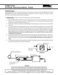
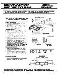
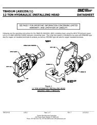
mpt-200a specifications and operating instructions - Daniels ...
mpt-200a specifications and operating instructions - Daniels ...
mpt-200a specifications and operating instructions - Daniels ...

Create successful ePaper yourself
Turn your PDF publications into a flip-book with our unique Google optimized e-Paper software.
MPT-200A SPECIFICATIONS ANDOPERATING INSTRUCTIONSDATASHEET1. SAFETYThe MPT-200A Wire Crimp Pull Tester is a force measurementdevice, <strong>and</strong> as such should be operated with due caution.Operator should wear safety glasses for eye protectionbecause the crimp under test may break suddenly <strong>and</strong> fragmentsmay fly off.Do not overload: The geared motor in the pull tester canexceed the load limits of the load cell component in this device.For your protection the MPT-200A has been factory setto stop if the peak force exceeds 205 Lb. Display blanking willoccur above 199.9 Lb.MPT-200ASPECIFICATIONSPERFORMANCECapacity: 200Lb (90.7Kg) (890N)Safe Overload: 150% of capacityReadout Accuracy: ± 0.5%Resolution: 0.1 lbSpeed Control Accuracy: ±1/8"/min. @ 1-5"/min. rate of pull±1/4"/min. @ 6-10"/min. rate of pullSt<strong>and</strong>ard Display: Pounds (XXX.X)Optional Display: Kilograms (XX.X), or Newtons (XXX)Operating Temperature: 50°F to 100°F (10°C to 38°C)Auto-stop enable/disable switchPHYSICALWeight: 26 Lb., less options.Height: 8 inchesWidth: 10 inchesDepth: 15 inchesCabinet: Painted carbon steelELECTRICALPower: 115VAC, 50/60 Hz std. (230VAC 50/60 Hz optional)OPTIONAL FEATURES AND ACCESSORIESDisplay units in KilogramsLb./Kilograms switchingDisplay units in NewtonsLb./Newtons switchingKg/Newtons switching7.5-30"/min. selectable rate of pull in ten 2.5"/min. incrementsUniversal self-tightening cam-type lower gripRing Terminal lower gripAdjustable setpoint for motor stop at preset forceConstant force pullRS232 output230VAC 50/60 Hz operation (International PowerCord Configuration)Slotted screw adjustment for Zero - Replaces st<strong>and</strong>ard knobadjustment2. SETUPThe Alphatron MPT-200A is shipped from the factoryprecalibrated <strong>and</strong> tested. To assure consistent, correct results,users should familiarize themselves with the setup <strong>and</strong> operationof the unit before placing it in service.To operate, set the MPT-200A on a flat, level surface in anupright position. Do not h<strong>and</strong>le, pick up or move the unit byexerting leverage against any front or rear panel controls, fixturesor connections. Always lift by the base plate, preferablyat the mid point along either side. DO NOT use the Lower Gripas a h<strong>and</strong>le for lifting or moving the MPT-200A. This can resultin permanent damage to the load cell sensing unit.3. ASSEMBLY3.1 UPPER GRIPThe MPT-200A is shipped with the upper grip installed.3.2 LOWER GRIPThe MPT-200A is shipped with the st<strong>and</strong>ard lowergrip installed. If an optional lower grip was ordered,it will be necessary for the purchaser to install it.3.2.1 Self-Tightening Cam-Type Lower Grip (optional)To install the Self-Tightening Cam-Type Lower Gripproceed as follows:A. Remove the screw holding the st<strong>and</strong>ard lowergrip in place.B. Place the screw in the mounting hole in the Self-Tightening Cam-Type Lower Grip. To get thescrew head past the <strong>operating</strong> gears into its recess,use the <strong>operating</strong> lever to rotate the camsinto the fully open position.C. Screw the assembly firmly into place in the loadcell sensing unit.DANIELS MANUFACTURING CORP., 526 THORPE ROAD, ORLANDO, FL 32824, USAPHONE (407) 855-6161 • FAX (407) 855-6884 • WWW.DMCTOOLS.COM • E-MAIL: DMC@DMCTOOLS.COM•COPYRIGHT © 2001 ALL RIGHTS RESERVED PAGE1OF6REV. C 5/01 FILE # DS0028 DOC # MPT-200A-DS
DATASHEETLBSPRINT(optional)ZEROWIRE CRIMP TESTER8888200 LB MAX CAPACITYMOTOR CONTROLN(optional)RESETSTART RESET STOPCRIMP GRIPAUTO STOPENABLEPEAKINOUTHILOWLO 1RATE OF PULLINCH/MINUTE6 7 8 9 101 2 3 4 5DISABLESET POINTS(optional)MEASURE(optional)CONTINUOUS(optional)SET(optional)3.2.2 Ring Terminal Lower Grip (optional)If the Ring Terminal Lower Grip option has been ordered,installation is as follows:A. Remove the screw holding the st<strong>and</strong>ard lowergrip in place.B. Substitute the optional grip for the st<strong>and</strong>ard grip<strong>and</strong> tighten the screw until the lower grip rotateswith resistance but is not loose or does not needto be forced to turn.MPT-200A FRONT VIEW<strong>and</strong> the Motor Control Stop Switch will be lighted.4.1.5 Allow 15 minutes warm-up before making validtests.4.2 LOWER GRIP4.2.1 (St<strong>and</strong>ard Grip) Rotate the lower grip to place thecorrect slot for the wire/terminal under test in theuppermost position. Select a slot that is the samewidth as the wire diameter, or one size larger.4. OPERATIONIn the <strong>instructions</strong> that follow operation of both st<strong>and</strong>ard<strong>and</strong> optional features will be covered.4.1 POWER4.1.1 Check the <strong>operating</strong> voltage of the unit. The correct<strong>operating</strong> voltage is on the identification labelon the back of the unit. Be sure that this voltage isthe same as the voltage available at your locationbefore you plug in the MPT-200A.4.1.2 Turn the power switch in the center of the backplate OFF.4.1.3 Plug the power cord into its receptacle on theback of the MPT-200A, <strong>and</strong> into the incoming powerreceptacle.4.1.4 Turn the power switch ON. The display will turn on4.2.2 Self-Tightening Cam-Type Lower-Grip (optional)Depress the <strong>operating</strong> lever of the Self-TighteningCam-Type Lower Grip to open it far enough to acceptthe sample under test. When you release thelever it will grip the sample.4.2.3 Ring Terminal Lower Grip (optional)Rotate the grip to place the correct stud uppermost<strong>and</strong> place the terminal over the stud.4.3 UPPER GRIP4.3.1 If the upper grip is not positioned as shown on theFront Panel drawing press the RESET button.4.3.2 Depress the <strong>operating</strong> lever of the Self-TighteningCam-Type Upper-Grip to open it far enough to acceptthe sample under test. When you release thelever it will grip the sample.4.4 FRONT PANEL CONTROLSDANIELS MANUFACTURING CORP., 526 THORPE ROAD, ORLANDO, FL 32824, USAPHONE (407) 855-6161 • FAX (407) 855-6884 • WWW.DMCTOOLS.COM • E-MAIL: DMC@DMCTOOLS.COM•COPYRIGHT © 2001 ALL RIGHTS RESERVED PAGE2OF6REV. C 5/01 FILE # DS0028 DOC # MPT-200A-DS
4.4.1 Motor Controls:A. START — motor start switch to begin test.B. RESET — resets peak hold meter to approximatezero <strong>and</strong> resets pull wheel to START positionfor the next test. Reset must be performedafter each test.NOTE: The peak hold meter does not alwaysreturn to an exact zero reading. If the meter readsless than .5 Lb. (in the Lb. mode) continue testing.If the figure is greater than .5 Lb. depressthe RESET switch next to the display. Thisshould clear the residual peak value. If it doesnot, adjust the meter ZERO (see section 4.6.2)C. STOP — Stops the motor, <strong>and</strong> the meter retainsthe current peak value.4.4.2 AUTO STOP — This feature stops the pull testwhen the piece under test fails. When the force appliedto the piece under test peaks <strong>and</strong> then fallsbelow 70% of the displayed reading, the test is completed<strong>and</strong> the unit stops.The ENABLE/DISABLE switch will have the followingeffect:ENABLE = AUTO STOP works.DISABLE = AUTO STOP doesn't work (the STOPswitch must be used at the completion of a test).NOTE: The AUTO STOP function will not operate ifthe test range is at or below approximately 4.5 to 6Lb. This is necessary to allow for the preload thatan operator will normally apply when inserting a connectorfor the test. If the preload is greater than thelower limit, the unit will not start. In this circumstanceit is necessary to decrease the preload <strong>and</strong>depress the meter RESET switch in order to be ableto start the test.If the test involves loads (connections) that will partat a force less than the lower limit, AUTO STOPdoes not function. Press the MOTOR CONTROLSTOP switch to stop the test when the connectionbreaks.4.5 RATE OF PULL CONTROLS4.5.1 LO-HI switchA. LO selects rate of pull of 1-5 in./min.B. HI selects rate of pull of 6-10 in./min.4.5.2 1-5 switches select rate of pull between 1-5 in./min.(LO), or 6-10 in./min. (HI) as chosen by settingof LO-HI switch.4.6 DISPLAY CONTROLS4.6.1 RESET — Resets the display (clears peak values)to zero. Use this switch when making zeroadjustments.DATASHEET4.6.2 ZERO adjusts the display to true zero. When turnedcounterclockwise the meter will not read a numbergreater than -01.0. Press meter RESET after eachincrement turned to arrive at zero. Several adjustmentsmay be necessary to reach exact zero.4.6.3 *Lb/Kg Switch (optional), switches the display toindicate pounds force of kilograms as the unit ofmeasure.4.6.4 *Lb/N Switch (optional), switches the display toindicate pounds force or newtons as the unit of measure.Decimal point switching is automatic.4.6.5 *Kg/N Switch (optional), switches the display toindicate KG force or newtons as the unit of measure.Decimal point switching is automatic.*NOTE: If using RS232 Digital output on an MPT-200Awith an optional units switch you must turn theMPT-200A off each time you switch units, so thatthe change can take effect in the digital output whenyou restart the MPT-200A4.7 OTHER OPTIONAL CONTROLS ON THEFRONT PLATE4.7.1 PRINT push-button. Activates RS232 output toserial printer or other RS232 compatible device.4.7.2 The SETPOINT option enables an operator to programthe force at which the MPT-200A is to stopautomatically if the test proceeds to that force <strong>and</strong>the connection under test does not fail.NOTE: When setting the force for the setpoint, thedisplay reading is in LBS. only. For systems usingkilograms or Newtons as the unit of measure a conversionfactor must be applied.1 lb = .454 KG.1 lb = 4.448 NSETPOINT/MEASURE when held in the MEASUREposition enables the operator to select the setpointby turning the SET adjusting knob next to the switch.As the knob is turned, the setpoint force will be indicatedon the peak hold meter. Clockwise adjustmentincreases the setpoint value, <strong>and</strong> turning theknob counterclockwise decreases the value.The force reading from the load cell is disabled, <strong>and</strong>will not be enabled until the switch is in theSETPOINT (raised) position.Tests are conducted with the switch in the raisedDANIELS MANUFACTURING CORP., 526 THORPE ROAD, ORLANDO, FL 32824, USAPHONE (407) 855-6161 • FAX (407) 855-6884 • WWW.DMCTOOLS.COM • E-MAIL: DMC@DMCTOOLS.COM•COPYRIGHT © 2001 ALL RIGHTS RESERVED PAGE3OF6REV. C 5/01 FILE # DS0028 DOC # MPT-200A-DS
position. When the load reaches the setpoint level,the motor will stop <strong>and</strong> the unit can be reset <strong>and</strong>reloaded for the next test.This option can be used in conjunction with the AUTOSTOP feature. When both features are turned on,the test will stop automatically if either condition ismet (AUTO STOP, or SETPOINT).If the peak reading of the force necessary to part aconnection is desired, the setpoint should be at199.9 Lb before testing. A connection requiring morethan that peak force to part will cause the digitaldisplay to go blank <strong>and</strong> the unit will stop automaticallywithout a peak reading.4.7.3 The CONSTANT FORCE option operates similarlyto the SETPOINT option. An additional switchis provided above the SET knob. The switch shouldbe set to PEAK for normal operation, <strong>and</strong> to CON-TINUOUS when using the CONSTANT FORCE option.4.8 SPECIAL FEATURES4.8.1 Optional Digital Output Board — RS232.The MPT-200A with the optional RS232 Digital OutputBoard is shipped from the factory ready for usewith all required communications parameters presetto the most common settings, Switches 1, 2,6, <strong>and</strong> 7 have been preset based on the displayunits <strong>and</strong> should not require any modification.If communication parameters are not compatiblewith interfacing hardware, it is necessary to set aseries of output parameters by means of the 8 switchDIP package installed on the board.REMEMBER: You must switch the unit off each timeany switch settings are changed in order to havethem take effect when you restart the MPT-200A.4.8.1.1 Switch LocationTo gain access to the Digital Output Board switchesit will be necessary to remove the left h<strong>and</strong> cover(when looking at the front of the machine) which isheld in place by two screws at the base plate. TheDigital Output Board is the top board, <strong>and</strong> the DIPswitches are on the edge nearest the center of themachine.4.8.1.2 Dip Switch Settings:See Table Below4.8.1.3 RS-232 I/O Port pin functionsPin 2 Rx received data to MPT-200APin 3 Tx transmitted data from MPT-200APin 5 (CTS) Normally high, goes low at start, highDATASHEETat stopPin 7 SG Signal GNDPin 24 Remote switch enable (normally open, momentarycontact)Pin 25 Signal ground for remote switch.4.8.1.4 RS-232 General SpecificationsCommunications System:....Full duplex serialDefinition: ............................DCEBaud Rate: ..........................Selectable - 300, 600, 1200,2400, 4800, 9600Start Bits: ............................1Data Bits: ............................8Parity:..................................NoneStop Bits: ............................1Coding: ................................ASCIITransmission Sequence: .....LSB firstEnd of Trans. Delimiters: .....CR LFData will be transmitted in response to any receivedcharacter on the Rx port or by pressing the PRINTbutton on the MPT-200A.SWITCH13 12 11 10 9 8 7 6 5 4 3 2 125 24 23 22 21 20 19 18 17 16 15 14#1ClosedClosedOpenSWITCH #3ClosedClosedClosedClosedOpenOpenOpenOpenSWITCH #6ClosedClosedOpenOpen#2ClosedOpenClosed#4ClosedClosedOpenOpenClosedClosedOpenOpen#7ClosedOpenClosedOpenSWITCH #8 Not used(1) Factory Settings (MPT-200A)#5ClosedOpenClosedOpenClosedOpenClosedOpenDECIMAL POINTxxxxxxx.x (1)xx.xxLBKGNLBBAUD RATE9600 (1)480024001200600300300300(Pounds) (1)(Kilograms)(Newtons)(Pounds)DANIELS MANUFACTURING CORP., 526 THORPE ROAD, ORLANDO, FL 32824, USAPHONE (407) 855-6161 • FAX (407) 855-6884 • WWW.DMCTOOLS.COM • E-MAIL: DMC@DMCTOOLS.COM•COPYRIGHT © 2001 ALL RIGHTS RESERVED PAGE4OF6REV. C 5/01 FILE # DS0028 DOC # MPT-200A-DS
DATASHEETFUSER-CALONOFFAUX. OUTPUTAC POWERMPT-200AMADE IN U.S.A.MPT-200A REAR VIEWCharacter 1 Space (for positive sign)2 Digit3 Digit or decimal point4 Digit or decimal point5 Digit or decimal point6 Digit or space7 Space8 Units (L K Space)9 Units (B G N)10 CR11 LF4.9 FUSEIf the main fuse requires replacement install a .3 Amp.125/250V slow blow fuse.5. FUNCTIONAL CHECKThe MPT-200A Wire Crimp Pull Tester is factory calibratedwith equipment traceable to the NIST. It is a recommendedpractice to recalibrate the unit at intervals not to exceed oneyear in duration.The functional check is executed using the R-cal switchbuilt into the unit. The R-cal switch is located behind the swingawaycover on the rear of the unit, <strong>and</strong> its R-cal value is on thesticker on the switch cover plate.A functional check can be performed at any time:1. Allow the MPT-200A to warm up for 15 minutes.2. Depress the reset toggle momentarily.3. Zero the display by alternately turning the zeroknob <strong>and</strong> momentarily pressing the reset toggleuntil the display reads 00.0.4. Press the R-cal button on the back of the unit(under the swing-away cover). Press the resettoggle to zero the display. Repeat this processseveral times to assure a repeatable value. Thedisplay value (R-cal # X .005 = toleranceR-cal # plus & minus tolerance = range)should be within +/- .5% the value recorded onthe swing-away cover.EXAMPLE: R-cal = 140.0140 X .005 = 0.7139.3 to 140.7 = range5. If any of the procedures in steps 2-4 do not producethe expected results, the unit should bereturned to DMC for repair <strong>and</strong> recalibration.Special information for Self-Tightening Cam-TypeLower Grip users:When you install the Self-Tightening Cam-Type LowerGrip the R-cal number may be different than the one thatis on the sticker.For your convenience we suggest that after the optionalgrip is installed, take an R-cal reading <strong>and</strong> recordit for use as the R-cal factor for this particular machine.DANIELS MANUFACTURING CORP., 526 THORPE ROAD, ORLANDO, FL 32824, USAPHONE (407) 855-6161 • FAX (407) 855-6884 • WWW.DMCTOOLS.COM • E-MAIL: DMC@DMCTOOLS.COM•COPYRIGHT © 2001 ALL RIGHTS RESERVED PAGE5OF6REV. C 5/01 FILE # DS0028 DOC # MPT-200A-DS
DATASHEETLIMITATION OF LIABILITY / LIMITED WARRANTY*DANIELS MANUFACTURING CORPORATION IS NOT LIABLE FOR CONSEQUEN-TIAL OR SPECIAL DAMAGES OF ANY NATURE OR KIND RESULTING FROM THE USEOF ANY OF ITS PRODUCTS. OWNERS AND USERS OF DMC PRODUCTS ASSUMEFULL RESPONSIBILITY FOR INSTRUCTING THEIR EMPLOYEES IN THE PROPER ANDSAFE USE OF SUCH PRODUCTS.<strong>Daniels</strong> Manufacturing Corporation warrants each new unit sold by it to be free fromdefects in material <strong>and</strong> workmanship under normal use <strong>and</strong> service. Its obligation under thiswarranty is limited to the free correction or, at its option, the refund of the purchase price ofany such unit which proves defective within ninety (90) days after delivery to the first user,provided that the unit is returned with all transportation charges prepaid, <strong>and</strong> which shallappear to its satisfaction, upon inspection by it, to have been defective in material or workmanship.This warranty shall not cover any damage to such products, which in the opinion of<strong>Daniels</strong> Manufacturing Corporation, was caused by normal wear, misuse, improper operationor accident. This warranty is in lieu of all other warranties express or implied. Nowarranty, express or implied, is made or authorized to be made or assumed with respect toproducts of <strong>Daniels</strong> Manufacturing Corporation, other than that herein set forth.*as defined by PL93-637DANIELS MANUFACTURING CORP., 526 THORPE ROAD, ORLANDO, FL 32824, USAPHONE (407) 855-6161 • FAX (407) 855-6884 • WWW.DMCTOOLS.COM • E-MAIL: DMC@DMCTOOLS.COM•COPYRIGHT © 2001 ALL RIGHTS RESERVED PAGE6OF6REV. C 5/01 FILE # DS0028 DOC # MPT-200A-DS