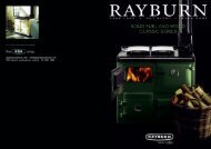
ESSE Cooking Stove - British Stoves
ESSE Cooking Stove - British Stoves
ESSE Cooking Stove - British Stoves

You also want an ePaper? Increase the reach of your titles
YUMPU automatically turns print PDFs into web optimized ePapers that Google loves.
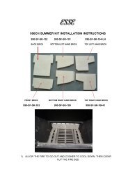
DOOR HINGE ADJUSTMENTS1) Remove upper & lower locking grub screwsfrom hinges using the 3/16” allan key provided.2) Using the same allan key, adjust either or botheccentric pins in each door hinge to level the door.Door3/16” Allan KeyLIGHTING AND CONTROLLING THE FIREFirebox parts - Fig.3Back bricksGratesSteel Baffle3) Once the door is level, lock the eccentric pins inplace using the locking grub screws.EccentricpinDoor HingeLockinggrub screwBefore lighting ensure that all the internalcomponents are in the correct position. (See Figure3 above).Open the ash door on the bottom left of thecooking stove by inserting the operating tool (SeeFigure 2 on page 3) into the handle slot and turningit in an anti-clockwise direction.Figure 1 on page 3 shows the primary air controllever on the left. Push the lever left to open andright to close. To light the cooking stove theprimary air control should be fully open.Open the loading door by lifting the handle eithermanually or using the operating tool.Figure 1 shows the secondary air control to the leftand the damper control to the right. As with theprimary air control, the secondary air control levershould be pushed left to open and right to close.The damper control is open when the knob ispulled out and closed when it is pushed in.To light the cooking stove the secondary air controlshould be fully open and the damper control pulledout. The flue restrictor should be opened bypointing the lever to the rear of the cooker (fig.1).This will allow fumes to escape directly up the fluewhilst the cooking stove warms up.Place some tightly rolled paper on top of somecrumpled paper on the base towards the back ofthe cooking stove. On top of this, place some smallpieces of wood. Light the crumpled paper andclose the door.Warning! When the cooking stove is runningthe handle will become hot and the operatingtool alone should then be used.WOODOnce the fire becomes established add somelarger pieces of wood. As the cooking stove comesup to temperature close the primary air control.The burning rate of the cooking stove can now beregulated by the rate at which fuel is added and byadjusting the secondary air control.SOLID FUELOnce the fire becomes established add some solidfuel. The rate at which solid fuel burns can becontrolled by using the primary air control and bythe amount of fuel added. The secondary aircontrol will affect the burning rate to a lesserdegree than the primary, but it should be left openwhere possible in order to keep deposits away fromthe glass window.Whichever fuel is used, the damper control may beclosed once the fire is established depending onoven requirements (See Operating the Oven andHob on page 6).Fuel placedat the rearof the fireboxAshpanAlternative flue bar positions - Fig.4Fuelbar fits into any ofthe grate slotsSide bricksNOTES ON WOODBURNINGWood burns most efficiently when the air forcombustion is supplied from above the fire bedrather than below. The air supplied above the firebed provides the oxygen necessary for the volatilegases (smoke), given off by the wood as it heats, tocombust. This ensures that the gases are burnt andused to heat the appliance instead of being wastedup the chimney or condensing and forming tarrydeposits inside the cooking stove, in the flue or onthe loading door glass.Running the cooking stove with the primary aircontrol open and the secondary air control closedwill provide oxygen for the wood to burn on thefire bed but will not provide air for the volatilegases above the fire bed to combust resulting in asmoky inefficient fire.With the above in mind the cooking stove shouldideally be run with the primary air inlet closed andthe secondary air control open whenever possible.Another advantage of running the cooking stovewith the air wash open is that the air being drawninto the cooking stove travels across the glass,forming an air barrier between the glass and thefire bed, helping to prevent smoke particlessticking to the glass.If the fire dies down too low, opening the primaryair control for a short period will revive it.4 5
CORRECT RUNNING TEMPERATURES FOR WOOD BURNINGOPERATING THE OVEN AND HOBTo get the best results from your cooking stove it isrecommended that a wood stove thermometer(available from your cooking stove dealer) be fittedto the flue pipe above the cooking stove, at eyelevel if possible. The figures below show therecommended temperature of the flue gases:115 °C - 245°C (240°F – 475°F)The flue gases should be in this temperature bandfor the safest, most efficient and most economicaloperation of your cooking stove.EXTENDED WOOD BURNINGLoading a large amount of wood into the cookingstove all at once will reduce the temperature inside.If the temperature is too low, the gases given offfrom the wood will be too low to combust,resulting in a lot of smoke which will cover theinside of the cooking stove, including the glass,with soot. To combat this problem it is a good ideato increase the temperature of the cooking stovebefore loading by further opening the air inlets.Load the wood and leave the air controls openuntil the moisture is driven out of the wood andthe cooking stove is back up to an efficientoperating temperature. The air inlets can then beTYPES OF WOOD FOR FUELFor best results use well seasoned hardwood suchas Oak, Ash, or Beech. Allow wood to dry outunder cover in well-ventilated conditions for atleast twelve months. Wood is ready for burningwhen radial cracks appear in the end of the logs.Burning wood that is not seasoned will result in tarbeing deposited in the cooking stove, on the glassand in the flueways.This build up of tar is a hazard and if it ignites maycause a chimney fire. Resinous softwood burns welland gives a high output for short periods but is notas efficient and does not last as long as hardwood.PEATPeat is a fuel conveniently available in some areasBelow 115°C (240°F)This is below the condensation point of wood gasesand may cause the build up of tar in the chimney,dirty the cooking stove glass and result in theinefficient burning of fuel.Above 245 °C (475°F)Too hot. Heat will be wasted up the chimney.Excess heat may damage the cooking stove orignite an existing accumulation of tar resulting in achimney fire.reduced to hold the temperature of the cookingstove. If excessive flue updraught is experienced,pull the flue restrictor lever to the front of thecooker to reduce the flue draught (fig.1). Loadingthe cooker stove little and often will help keep thecooking stove temperature steady.Note: The above text should be used as a guideonly. The ideal operation of your cooking stovedepends on a number of factors, which vary witheach installation, and so gaining experienceoperating your cooking stove is the only way tolearn its best operation.and should be burned in the same manner as wood.ASH REMOVALWood burns best on its own ash and a manageablelayer of ash on the grate is of benefit to the efficientrunning of your cooking stove. To empty the ashesfrom the ashpan below the grate, open the door onthe bottom left of the cooking stove using theoperating tool by inserting the tool into the slotand turning anti-clockwise. Insert the tool into theslot on the ash pan and pull forwards to remove.Care should be taken when disposing of ashes thatare still warm. They should not be put into a plasticreceptacle or anything that might melt in contactwith heat.The temperature of the hob is graduated from leftto right. The left side is hotter and so is used forboiling and the right side for simmering. The ovendoor and the fire door are opened by lifting thehandle either manually or using the operating tool.Both handles will become hot during operationwhen a cloth or the operating tool provided isrecommended.The oven and hob are heated directly by the fire. Inorder to heat up the oven and hob the fire shouldbe lit as described above. Once the fire isestablished the flue damper should be pushed in.This will allow the hot fumes from the fire to circulatearound the inner cavity between the cooking stoveand the oven thus heating up both the hob and theoven.The hob lids can be left down when the hob is notbeing used in order to keep the hotplates warm. In theup position they will allow more heat into the room.To reduce the heat going to the oven when theCLEANING THE COOKING STOVEThe cooking stove should only be cleaned when itis cold. The exterior can be dusted with a firm brush.Do not use a cloth to clean, as this will drag on thepaint finish leaving lint on the surface.As the cooking stove top is used for cooking,normal wear and tear will occur. Spills should bemopped up immediately with a damp cloth, butoven cleaners should not be used on the hobsurface.The exterior of the cooking stove is painted withhigh temperature cooking stove paint and fromtime to time it may become necessary to renovatethe exterior by repainting. The surface must beprepared by rubbing down with a wire brush. Thecooking stove paint will not key to the surface ifthere are fat deposits or food particles on the areato be resprayed. High temperature cooking stovepaints are available in aerosol form from yourcooking stove dealer. Do not use this paint until thecooking stove is completely cold and always followthe instructions on the container before starting tocooking stove is up and running, the flue damperknob can be pulled out. This will allow the hotfumes to escape directly up the chimney via theboiling side of the hotplate, thus reducing the heatto the oven but maintaining a hot hotplate.To maintain a good cooking temperature in theoven requires only a small amount of fuel. Toreduce the effective size of the firebox, the fuel barcan be moved towards the back and thus used tohold a smaller amount of fuel at the rear of thefirebox, see Figure 4 on page 4. This also has theadvantage of reducing the heat radiated throughthe window, making life easier for the cook.The temperature gauge on the oven door providesan indication of the oven temperature. It should benoted however that since the gauge is attached tothe door it will drop if the door is left open for anyprolonged period, in which case, the oven may behotter than is indicated on the dial. Once the dooris closed again the gauge will come back totemperature.paint. The usual precautions should be taken, suchas covering adjoining surfaces and protecting thehob lids.The hob lids are made from stainless steel. Thesehave been treated with oil at the factory to preventfingerprints and marks forming. The lids can bewiped clean with a damp cloth and proprietarystainless steel cleaners may be used. It isrecommended that after such cleaning, the lids beagain treated with oil by wiping over with a lintfree cloth. This will prevent fingerprints andsmears. Baby oil or similar is recommended for thispurpose.The loading door glass should stay relatively cleanif the correct type of fuel is used as describedabove, but from time to time this can be cleanedwhen cold with a proprietary glass cleaner and adry cloth, or depending on soot build up, a nylonpan scourer. Vinegar and newspaper may alsosuccessfully be used.6 7
HOT WATER SYSTEMINSTALLATION INSTRUCTIONSSA) There are two connections, both 1” BSP Male –on the left hand side one connection for hotwater. The storage cylinder should be 30gallon nominal capacity insulated to preventHeat loss and as close to the cooker as possible.Follow general notes below item (C) (6), (7) & (8).B) The EWB or DE-LUXE boiler is plainmild steel and capable of running a radiator inaddition to domestic hot water.Follow all general notes.C) General Notes on Water System: -1) The cooker will produce hot water atdiffering rates depending on how it isoperated. Heating control is manual, nothermostat is fitted.2) The system must be designed to cope withloads between the maximum and minimumoutput. When the central heating load isturned off there must be sufficient gravity loadto absorb 15,000 Btu/h for periods when theoven is being used for cooking, e.g. Domestichot water plus gravity operated radiator.3) An indirect storage cylinder is essential fordomestic hot water supply, irrespective ofwhether the water supply is hard or soft.Minimum capacity 30 gallons.Cylinder should be as close to cooker as possible.4) The central heating circuit may be gravitycirculation, but a pumped system is preferred.To allow heat from the boiler to be absorbedshould there be a pump stopage on anaccelerated circuit, the primary domesticsupply must be gravity operated.5) Installation as a central heating system alone,i.e. without a domestic supply, is notrecommended as the boiler will produce heatwhen the cooker is in use, irrespective ofcentral heating demand, and primary absorptionmust be provided.6) Whichever system is chosen the layout mustfollow established heating engineering practice.To avoid trapping air in the boiler a 1” BSPconnection must be used on the flow trapping,and any reduction in pipe size thereafter beingmade on a vertical rising pipe. The cooker mustbe level when fitted and the flow pipe must risefrom the boiler. A drain cock must be fitted onthe lowest point of the return pipe and a vent toatmosphere at the highest point of each circuit.7) The cylinder and pipe work should be lagged toavoid heat loss.8) The static head must not exceed 60 feet of water.200mm200mm200mmThe installer has a responsibility under the Healthand Safety at Work Act 1974 to provide for thesafety of persons carrying out the installation.Attention is drawn to the fact that fire cement iscaustic and hands must be washed thoroughly afteruse. The appliance is heavy and care must be takenduring handling. Although the appliance does notcontain asbestos products, it is possible thatasbestos may be disturbed in existing installationsand every precaution must be taken.These instructions give a guide for the installationof the appliance but in no way absolves the installer416mmmin. clearancefor hob lid200mmClearances - Fig.5Clearance to the back wall canbe zero if non-combustible.For a wall containing anycombustible material theclearance should be 400mm.from responsibilities to conform to <strong>British</strong>Standards, in particular BS8303 and BS6461,relating to the installation of solid fuel appliances.The installation should also comply with localBuilding Regulations and Local Authority Bye-Laws.Any adjacent combustible material should be farenough away from the cooking stove so as not torise 60°C above the room temperature when thecooking stove is in operation. If necessary, anyadjoining walls should be protected from theeffects of heat.CHIMNEY AND FLUEThe successful operation of the cooking stove relieson the adequate performance of the chimney towhich it is connected. The chimney must:● Be terminated at least 1m above roof level sothat the chimney does not terminate in apressure zone. See Figure 6 on page 10.● Have an internal cross section of no less than 320cm.sq (200mm dia.). (If a flue liner is used itshould be 6” diameter and suitable for solid fuel).● Be a minimum 4.6m high from hearth level to pot.● Be free from cracks, severe bends, voids, andobstructions.● Be connected to this one appliance only.● New chimneys must be built in accordance withlocal building regulations.8 9
● If the cooking stove is installed as a freestandingappliance, it should not support any part of thechimney.● Voids in the chimney should be avoided as thesewill prevent a steady flue draught. The cookingstove flue pipe should pass beyond thenarrowing of the chimney.FLUE DRAUGHTThe chimney can be checked, before the cookingstove is installed, with a smoke match. If thechimney doesn’t pull the smoke it may suggest thechimney needs attention (see the Flue DiagnosisTable on page 11).FLUE DRAUGHT READINGTwo flue draught readings should be taken, onewith the cooking stove at minimum firing rate andone at maximum firing rate. The flue draught testhole must be drilled in the flue pipe as close to thecooking stove as possible and before any fluedraught stabiliser.MINIMUMThe cooking stove should be lit and allowed towarm the flue thoroughly. The air controls canthen be set so that the cooking stove burns on a lowsetting. Allow the burning rate to become steady.The flue draught reading should now be taken withthe primary air intake closed and the secondary aircontrol fully open.Chimney and Flue - Fig.6● A flue/chimney access point may also berequired so that the state of the chimney can bechecked and any fallen soot removed.● External flues must be insulated to prevent heat loss.Note: This test is only a guide as an apparentlypoor flue may improve once the cooking stove isinstalled, lit and the flue is warmed. If, once thecooking stove is installed, there is any doubt thatthe chimney is providing an adequate draught, aflue draught reading should be taken.MAXIMUMThe primary air intake can now be opened to allowthe cooking stove to burn at maximum rate. Givethe cooking stove some time for the burning rate tobecome steady and then close the primary airintake. Make sure the secondary air control is fullyopen and take a flue draught reading immediately.Ideally, the flue draught readings should rangebetween 1 mm wg (0.04 in wg) and 2.5 mm wg(0.1 in wg).Any readings significantly outside this range mayindicate the need for remedial action.Low flue draught symptoms: difficult to light and smoke coming into the room.CauseCold chimneyChimney too shortDown draughtChimney diameter too largeChimney obstructionRestricted air supplyHigh flue draught symptoms: fire difficult to control, fuel will not last, cooking stove too hot, cooking stove damage, chimney fireCauseExternal wind conditions combined with chimney terminalFLUE STABILIZERA flue stabilizer can be fitted to reduce the draughtthrough the cooking stove if the flue draught is toohigh. The flue stabilizer should be fitted in theINSTALLING THE COOKING STOVEPOSITIONINGThe overall dimensions of the cooking stove areshown in Figure 1 on page 3. Figure 4 on page 4shows recommended distances between thecooking stove and surrounding flammablematerials. As a rule, any surrounding flammablematerial should not exceed 60°C above ambientroom temperature.FLUE CONNECTIONThe flue pipe used to connect the cooking stove tothe chimney is 6” (150mm) in diameter.The flue connection is on the top of the cookingstove, in the center at the back.RemedyLine the chimneyExtend the chimneyRelocate/extend chimney terminal. Fit an anti downdraught cowlLine the chimneyClear/sweep the chimneyCheck for competing draughts (other chimneys,extractor hoods/fans). Fit an air vent if the room issealed.RemedyFit stabilizer cowl. Fit flue draught stabilizer.same room as the cooking stove, be the same sizeas the flue pipe and be fitted no closer than 700mmto the flue outlet of the appliance.IMPORTANT INSTALLATION NOTES:1. The installation must allow for adequatechimney sweeping.2. Avoid using bends greater than 45° to thevertical. All flue pipe sections should be as closeto vertical as possible.3. All joints in the flue system must be effectivelysealed.4. All flue sockets must face upwards. Oncompleting the installation, check that all theinternal components of the cooking stove arepositioned correctly. Check: Grate, baffle, ashpan, insulation bricks, fuel bar. See Figure 3 onpage 4.10 11
SPARE PARTS1 Upper Door Handles2 Lower Door Handles3 Fire Guard4 Cast Fire Door5 Ash Door6 Magnet Catch7 Temperature Clock8 Ceramic Glass Window9 Flue Access Door10 Oven Door Liner11 Fuel Guard12 Stainless Baffle13 Flue Access Plate14 Ashpan15 Grate16 Oven Tray17 Lower Slider18 Cast Shelf Supports19 Door Hinge Assembly20 Wire Shelf21 Steel Baffle22 Upper Slider23 Flue Heat Shield24 Hand Rail25 Flue Restrictor Guide26 Side Panel27 Hand Rail Bracket28 Hotplate29 Cast Top30 Flue Restrictor31 <strong>Stove</strong> Body32 Bottom Heat Shield33 Legs34 Rear Heat Shield35 Side Panel36 Cast Flue Box and Door37 5” to 6” Adaptor38 Bolster Lid Assembly39 Fire Bricks40 Cast Iron Door41 Charcoal Spray Can12 13
COMMISSIONING RECORDEngineers NameDateEngineers NameDateAddressAddressTel No.Fax No.Tel No.Fax No.HETAS/Reg No.HETAS/Reg No.SERVICE RECORDEngineers NameAddressDateEngineers NameDateAddressTel No.Fax No.HETAS/Reg No.Tel No.Fax No.HETAS/Reg No.Engineers NameDateAddressEngineers NameDateAddressTel No.Fax No.HETAS/Reg No.Tel No.Fax No.HETAS/Reg No.Engineers NameDateEngineers NameDateAddressAddressTel No.Fax No.Tel No.Fax No.HETAS/Reg No.HETAS/Reg No.14 15