

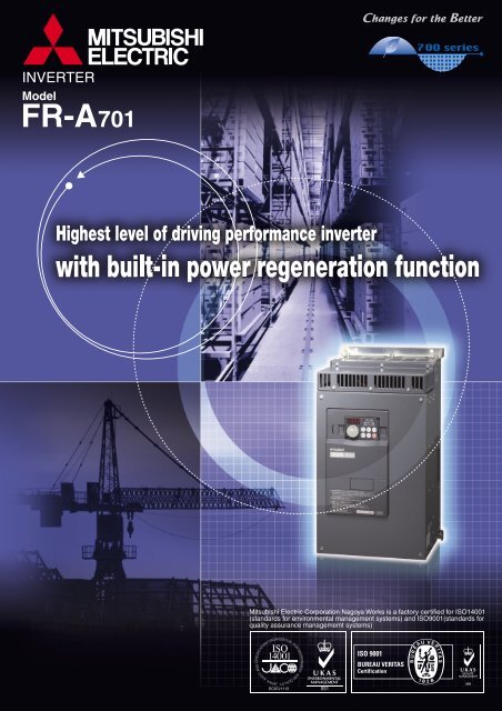
FR-A701 catalog - Mitsubishi Electric Australia
FR-A701 catalog - Mitsubishi Electric Australia
FR-A701 catalog - Mitsubishi Electric Australia

Create successful ePaper yourself
Turn your PDF publications into a flip-book with our unique Google optimized e-Paper software.
Inverter with built-in power regeneration function,achieving great braking capability and reductionin wiring length/space saving• Features1The <strong>FR</strong>-<strong>A701</strong> series, which is a high functional inverter <strong>FR</strong>-A700 series equipped with powerregeneration function, achieving great braking capability is now available. This compact body inverterwith variety of advanced technology attained high performance suitable for lift operation, line control,etc. It contributes to high performance of machine equipment which generate regeneration torque suchas elevator, centrifugal separator, various testing machine, winding machine, etc.FeaturesInverter and power regeneration converter are integrated into one body to enclosure and it is easy to perform enclosure designing<strong>FR</strong>-A•The number of main circuit wires is down to approx. 40% and the installation area in case of 7.5K is down to approx. 60% ascompared to the conventional common converter stand-alone type. Reduction in wiring-length/space is enabled.•In consideration of intercompatibility, installation size is kept the same as the conventional model (<strong>FR</strong>-A201 series).•Since a braking circuit is built-in, it is not necessary to consider to select a braking unit.Comparison (7.5K):Installation area<strong>FR</strong>-A721-7.5KPower supplyGreat braking capability by power regeneration function<strong>FR</strong>-ARegenerative braking torque has enough allowance forregeneration; 100% torque continuous and 150% torque 60s.High function/high performance elements of inverter are employedThe inverter was developed based on the <strong>FR</strong>-A700 and isequipped with the highest level of driving performance, long lifeparts, life diagnostic function, network connection* 2 ,environmental friendly* 1 , easy operation* 2 , and easy maintenance.Wide variety of lineupWide variations from 5.5kW to 55kW for the 200V class and400V class each are available.250Motor470Main circuit wiring: 6 lines only for input/outputInstallation area ratio: approx. 60%<strong>FR</strong>-A*1: The EMC filter, which was built-in to <strong>FR</strong>-A700 series, is not available for this series.*2: Because the <strong>FR</strong> Configurator has not worked with the <strong>FR</strong>-<strong>A701</strong> series, a USB connector can not be used.<strong>FR</strong>-A<strong>FR</strong>-CV-7.5K<strong>FR</strong>-CVL-7.5K3001001559050Power supply360Total cost-reduction can be achievedAs compared with the combination of the conventional system(inverter+power regeneration converter+AC reactor), total costreductioncan be achieved. Since regeneration energy is returnedto the power supply, less heat is generated as compared to theresistor driving method, and energy saving effect can be expected.Overseas standard/EU restriction of the use of certainhazardous substances (RoHS) directive compliance220MotorThis product is certified by UL and cUL.Complies with EN (LVD) standards. (400V class only)260555<strong>FR</strong>-A720-7.5KMain circuit wiring: 16 lines for input/outputInstallation area ratio: approx. 100%<strong>FR</strong>-A<strong>FR</strong>-APower regenerationModel configuration<strong>FR</strong> - A721 - 5.5KApplicationsSymbol Voltage classA721 200V classA741 400V class•Multilevel car parking towerSymbol Applicable motor capacity5.5KIndicate capacity55K(kW)•Overhead crane• Standardspecifications• OutlineDimensionDrawings• Terminal ConnectionDiagram• Terminal SpecificationExplanation• Parameter List 13• ProtectiveFunctions• Option andPeripheral Devices• Precautions forOperation/Selection• Precautions forPeripheral DeviceSelection1 2Powersupply<strong>FR</strong>-<strong>A701</strong>AC reactor(<strong>FR</strong>-HAL equivalent)Three-phase200V class<strong>FR</strong>-A721-Three-phase400V class<strong>FR</strong>-A741-Energy flow at regeneration~IMRegeneration energy is returnedto power supply in this section.•Power regeneration provides great braking power by returningregeneration energy from the motor to the power supply.Applied motor(kW)OperationpanelProgrammablecontroller5.5 7.5 11 15 18.5 22 30 37 45 55<strong>FR</strong>-<strong>A701</strong>Motor: Available modelsOperation time(sec)Characteristic7.5K5.5K500300200100503010G10 20 30 40 50 60 70 80Short time permissible regeneration power (kW)Trolley lineTravelingmotorIM<strong>Electric</strong>room11K15K18.5K22KCraneTrolley lineWIM30K37K45K55KHoistingmotorTravelingmotorIM GTravelingwheelRail• Warranty• Service• InternationalFA Center35102426333738
Standard SpecificationsRating•200V classType <strong>FR</strong>-A721-K 5.5 7.5 11 15 18.5 22 30 37 45 55Applicable motor capacity (kW) *1 5.5 7.5 11 15 18.5 22 30 37 45 55Rated capacity (kVA) *2 9.2 12.6 17.6 23.3 29 34 44 55 67 82Rated current (A) 24 33 46 61 76 90 115 145 175 215Overload current rating *3150% 60s, 200% 3s (inverse time characteristics)surrounding air temperature 50°CVoltage *4Three-phase 200 to 240VRegenerative braking torque100% continuous 150% 60sRated inputAC voltage/frequencyThree-phase 200 to 220V 50Hz, 200 to 240V 60HzPermissible AC voltage fluctuation170 to 242V 50Hz,170 to 264V 60HzPermissible frequency fluctuation ±5%Power supply capacity (kVA) *5 12 17 20 28 34 41 52 66 80 100Protective structure (JEM 1030) *6Open type (IP00)Cooling systemForced air coolingApprox. mass (kg) 20 22 33 35 50 52 69 87 90 120OutputPower supply•400V classType <strong>FR</strong>-A741-K 5.5 7.5 11 15 18.5 22 30 37 45 55Applicable motor capacity (kW) *1 5.5 7.5 11 15 18.5 22 30 37 45 55Rated capacity (kVA) *2 9.1 13 17.5 23.6 29 32.8 43.4 54 65 84Rated current (A) 12 17 23 31 38 44 57 71 86 110Overload current rating *3150% 60s, 200% 3s (inverse time characteristics)surrounding air temperature 50°CVoltage *4Three-phase 380 to 480VRegenerative braking torque100% continuous 150% 60sRated inputAC voltage/frequencyThree-phase 380 to 480V 50Hz/60HzPermissible AC voltage fluctuation323 to 528V 50Hz/60HzPermissible frequency fluctuation ±5%Power supply capacity (kVA) *5 12 17 20 28 34 41 52 66 80 100Protective structure *6Open type (IP00)Cooling systemForced air coolingApprox. mass (kg) 25 26 37 40 48 49 65 80 83 115OutputPower supply*1. The applicable motor capacity indicated is the maximum capacity applicable for use of the <strong>Mitsubishi</strong> 4-pole standard motor.*2. The rated output capacity indicated assumes that the output voltage is 220V for 200V and 440V for 400V class.*3. The % value of the overload current rating indicated is the ratio of the overload current to the inverter's rated output current. For repeated duty, allow timefor the inverter and motor to return to or below the temperatures under 100% load.*4. The maximum output voltage does not exceed the power supply voltage. The maximum output voltage can be changed within the setting range. However,the pulse voltage value of the inverter output side voltage remains unchanged at about 2 that of the power supply.*5. The power supply capacity varies with the value of the power supply side inverter impedance (including those of the input reactor and cables).*6. <strong>FR</strong>-DU07:IP40 (except for the PU connector)3
Common SpecificationsControl specificationsOperation specificationsIndicationSoft-PWM control/high carrier frequency PWM control (selectable from among V/F control, advanced magnetic flux vector control andControl methodreal sensorless vector control) / vector control *1Output frequency range 0.2 to 400Hz (The maximum frequency is 120Hz under real sensorless vector control and vector control *1.)FrequencysettingresolutionAnalog inputDigital inputFrequency Analog inputaccuracy Digital inputVoltage/frequency characteristicsStarting torqueTorque boostAcceleration/deceleration timesettingDC injection brakeStall prevention operation levelTorque limit levelFrequency Analog inputsettingsignalDigital inputStart signalInput signalsPulse train inputOperational functionsOutput signalsOperating statusWhen used with the<strong>FR</strong>-A7AY, <strong>FR</strong>-A7AR(option)Pulse train outputPulse/analog outputPU(<strong>FR</strong>-DU07/<strong>FR</strong>-PU07/<strong>FR</strong>-PU04)Operating statusFault definitionInteractive guidanceProtective/warning function0.015Hz/0 to 60Hz (terminal 2, 4: 0 to 10V/12bit)0.03Hz/0 to 60Hz (terminal 2, 4: 0 to 5V/11bit, 0 to 20mA/about 11bit, terminal 1: 0 to ±10V/12bit)0.06Hz/0 to 60Hz (terminal 1: 0 to ±5V/11bit)0.01HzWithin ±0.2% of the max. output frequency (25°C±10°C)Within 0.01% of the set output frequencyBase frequency can be set from 0 to 400Hz Constant torque/variable torque pattern or adjustable 5 points V/F can be selected150% 0.3Hz (under real sensorless vector control or vector control)Manual torque boost0 to 3600s (acceleration and deceleration can be set individually), linear or S-pattern acceleration/deceleration mode, backlashmeasures acceleration/deceleration can be selected.Operation frequency (0 to 120Hz), operation time (0 to 10s), operation voltage (0 to 30%) variableOperation current level can be set (0 to 220% adjustable), whether to use the function or not can be selectedTorque limit value can be set (0 to 400% variable)• Terminal 2, 4: 0 to 10V, 0 to 5V, 4 to 20mA (0 to 20mA) can be selected• Terminal 1: -10 to +10V, -5 to +5V can be selectedInput using the setting dial of the operation panel or parameter unitFour-digit BCD or 16 bit binary (when used with option <strong>FR</strong>-A7AX)Forward and reverse rotation or start signal automatic self-holding input (3-wire input) can be selected.You can select any twelve signals using Pr. 178 to Pr. 189 (input terminal function selection) from among multi speed selection, remote setting,stop-on-contact, second function selection, third function selection, terminal 4 input selection, JOG operation selection, selection ofautomatic restart after instantaneous power failure, flying start, external thermal relay input, PU operation/external inter lock signal , externalDC injection brake operation start, PID control enable terminal, brake opening completion signal, PU operation/external operationswitchover, load pattern selection forward rotation reverse rotation boost, V/F switching, load torque high-speed frequency, S-patternacceleration/deceleration C switchover, pre-excitation, output stop, start self-holding selection, control mode changing, torque limit selection,start-time tuning start external input, torque bias selection 1, 2 *1, P/PI control switchover, forward rotation command, reverse rotationcommand, inverter reset, PTC thermistor input, PID forward reverse operation switchover, PU-NET operation switchover, NET-externaloperation switchover, command source switchover, conditional position pulse train sign *1, conditional position droop pulse clear *1, andmagnetic flux decay output shutoff.100kppsMaximum/minimum frequency setting, frequency jump operation, external thermal relay input selection, polarity reversible operation,automatic restart after instantaneous power failure operation, electronic bypass operation, forward/reverse rotation prevention, remotesetting, brake sequence, second function, third function, multi-speed operation, original operation continuation at instantaneous powerfailure, stop-on-contact control, load torque high speed frequency control, droop control, regeneration avoidance, slip compensation,operation mode selection, offline auto tuning function, online auto tuning function, PID control, computer link operation (RS-485),motor end orientation*1, pre-excitation, notch filter, easy gain tuning, speed feed forward, and torque bias*1You can select any signals using Pr. 190 to Pr. 196 (output terminal function selection) from among inverter running, inverter running/startcommand on, up-to-frequency, instantaneous power failure/undervoltage, overload warning, output frequency (speed) detection, secondoutput frequency (speed) detection, third output frequency (speed) detection, electronic thermal relay function pre-alarm, PU operationmode, inverter operation ready 1, 2, output current detection, zero current detection, PID lower limit, PID upper limit, PID forward rotationreverse rotation output, electronic bypass MC1, electronic bypass MC2, electronic bypass MC3, orientation complete*1, orientationerror*1, brake opening request, fan fault output, heatsink overheat pre-alarm, deceleration at an instantaneous power failure, PID controlactivated, during retry, PID output interruption, position control preparation ready*1, life alarm, power savings average value updatetiming, current average monitor, fault output 1, 2, 3 (power-off signal), maintenance timer alarm, remote output, forward rotation output*1,reverse rotation output*1, low speed output, torque detection, regenerative status output *1, start-time tuning completion, in-positioncompletion*1, alarm output and fault output. Open collector output (5 points), relay output (2 points) and alarm code of the inverter can beoutput (4 bit) from the open collector.In addition to the above, you can select any signals using Pr. 313 to Pr. 319 (extension output terminal function selection) from among controlcircuit capacitor life, main circuit capacitor life, cooling fan life, inrush current limit circuit life. (only positive logic can be set for extensionterminals of the <strong>FR</strong>-A7AR)50kppsYou can select any signals using Pr. 54 FM terminal function selection (pulse train output) and Pr. 158 AM terminal function selection (analogoutput) from among output frequency, motor current (steady or peak value), output voltage, frequency setting, operation speed, motortorque, converter output voltage (steady or peak value), electronic thermal relay function load factor, input power, output power, loadmeter, motor excitation current, reference voltage output, motor load factor, power saving effect, PID set point, PID measured value,motor output, torque command, torque current command, and torque monitor.Output frequency, motor current (steady or peak value), output voltage, frequency setting, running speed,motor torque, overload,converter output voltage (steady or peak value), electronic thermal relay function load factor, input power, output power, load meter,motor excitation current, cumlative energization time, actual operation time, motor load factor, cumulative power, energy saving effect,cumulative saving power, PID set point, PID measured value, PID deviation, inverter I/O terminal monitor, input terminal optionmonitor*2, output terminal option monitor*2, option fitting status*3, terminal assignment status*3, torque command, torque currentcommand, feed back pulse*1,motor outputFault definition is displayed during the fault occurs, the output voltage/current/frequency/cumulative energization time right before thefault occurs and past 8 fault definitions are stored.Function (help) for operation guide*3Overcurrent during acceleration, overcurrent during constant speed, overcurrent during deceleration, overvoltage during acceleration,overvoltage during constant speed, overvoltage during deceleration, inverter protection thermal operation, motor protection thermaloperation, heatsink overheat, instantaneous power failure occurrence, undervoltage, input phase failure, motor overload, output sideearth (ground) fault overcurrent, output short circuit, main circuit element overheat, output phase failure, external thermal relayoperation*5, PTC thermistor operation*5, option alarm, parameter error, PU disconnection, retry count excess*5, CPU alarm, operationpanel power supply short circuit, 24VDC power output short circuit, output current detection value excess*5, inrush current limit circuitalarm, communication alarm (inverter), opposite rotation deceleration error*5, analog input error, fan fault, overcurrent stall prevention,overvoltage stall prevention, electronic thermal relay function prealarm, PU stop, maintenance timer alarm*2*5, parameter write error,copy operation error, operation panel lock, parameter copy alarm, speed limit indication, signal loss detection*1*5, speed deviationlarge*1*5, overspeed*1*5, excessive position error*1*5, encoder phase error*1*5, regeneration converter overcurrent, regenerationconverter circuit fault, regeneration converter transistor protection thermal, brake sequence error*5Ambient temperature-10°C to +50°C (non-freezing)Ambient humidity90%RH maximum (non-condensing)Storage temperature*4 -20°C to +65°CAtmosphereIndoors (without corrosive gas, flammable gas, oil mist, dust and dirt etc.)Altitude/vibrationMaximum 1000m above sea level, 5.9m/s 2 or less*1 Available only when the option (<strong>FR</strong>-A7AP) is mounted.*2 Can be displayed only on the operation panel (<strong>FR</strong>-DU07).*3 Can be displayed only on the parameter unit (<strong>FR</strong>-PU07/<strong>FR</strong>-PU04).*4 Temperature applicable for a short period in transit, etc.*5 This protective function does not function in the initial status.EnvironmentTerminal ConnectionDiagramTerminal SpecificationExplanationFeaturesStandardSpecificationsOutlineDimensionDrawingsParameterListProtectiveFunctionsOptionsInstructionsWarrantyInquiry4
Outline Dimension Drawings• <strong>FR</strong>-A721-5.5K, 7.5K• <strong>FR</strong>-A741-5.5K, 7.5K2-φ10 hole454470425101902502702.3205170100D1 D2Inverter Type D1 D2<strong>FR</strong>-A721-5.5K, 7.5K 163 90<strong>FR</strong>-A741-5.5K, 7.5K 168 85234(Unit: mm)•<strong>FR</strong>-A721-11K, 15K•<strong>FR</strong>-A741-11K, 15K2- φ10 hole1557560010220300102943.2255169125D2D1540Inverter Type D1 D2<strong>FR</strong>-A721-11K, 15K 213 64<strong>FR</strong>-A741-11K, 15K 224 53284(Unit: mm)5
•<strong>FR</strong>-A721-18.5K, 22K•<strong>FR</strong>-A741-18.5K, 22K122- φ12 holeW1W10 575 15600320FAN3.2535FeaturesStandardSpecificationsOutlineDimensionDrawingsW2130 190D2D1Inverter Type D1 D2 W W1 W2 W3<strong>FR</strong>-A721-18.5K, 22K 219 84 390 290 345 370<strong>FR</strong>-A741-18.5K, 22K 238 65 360 260 315 340Terminal ConnectionDiagramTerminal SpecificationExplanationW3(Unit: mm)ParameterList•<strong>FR</strong>-A721-30K•<strong>FR</strong>-A741-30K12 3502- φ12 hole45010 675 15700340FAN635ProtectiveFunctionsOptionsInstructions145 195405D1 D2Inverter Type D1 D2<strong>FR</strong>-A721-30K 240.5 82.5<strong>FR</strong>-A741-30K 252.5 70.5Warranty430(Unit: mm)Inquiry6
•<strong>FR</strong>-A721-37K, 45K•<strong>FR</strong>-A741-37K, 45K2- φ14 hole1437047040515 670 15700368FAN3.2630205163D2D1Inverter Type D1 D2<strong>FR</strong>-A721-37K, 45K 257.5 93.5<strong>FR</strong>-A741-37K, 45K 281.5 69.5450(Unit: mm)•<strong>FR</strong>-A721-55K•<strong>FR</strong>-A741-55K152- φ14 holeFAN87090083014480600154053.2555190 215D1 D2Inverter Type D1 D2<strong>FR</strong>-A721-55K 312 76<strong>FR</strong>-A741-55K 324.5 64580(Unit: mm)7
Heatsink protrusion procedureWhen encasing the inverter in an enclosure, the generated heat amount in an enclosure can be greatly reduced by installingthe heatsink portion of the inverter outside the enclosure.When installing the inverter in a compact enclosure, etc., this installation method is recommended.•Protrusion of heatsink• Panel cuttingCut the panel of the enclosure according to the inverter capacity.Features4-C screwH1 H3HStandardSpecificationsOutlineDimensionDrawingsTerminal ConnectionDiagramTerminal SpecificationExplanationW1WInverter Type W W1 H H1 H2 H3 CH2ParameterList<strong>FR</strong>-A721-5.5K, 7.5K<strong>FR</strong>-A741-5.5K, 7.5K240 190 454 434 12 8 M8<strong>FR</strong>-A721-11K, 15K<strong>FR</strong>-A741-11K, 15K290 220 575 548 17 10 M8<strong>FR</strong>-A721-18.5K, 22K 376 290 575 546 17 12 M10ProtectiveFunctions<strong>FR</strong>-A741-18.5K, 22K 346 260 575 546 17 12 M10<strong>FR</strong>-A721-30K<strong>FR</strong>-A741-30K<strong>FR</strong>-A721-37K, 45K<strong>FR</strong>-A741-37K, 45K436 350 675 646 17 12 M10456 370 670 641 17 12 M12Options<strong>FR</strong>-A721-55K<strong>FR</strong>-A741-55K586 480 870 841 17 12 M12InquiryWarrantyInstructions8
• Shift and removal of a rear side installation frameOne installation frame is attached to each of the upper and lower parts of the inverter. Change the position of therear side installation frame on the upper and lower sides of the inverter to the front side as shown on the right.When changing the installation frames, make sure that the installation orientation is correct.ShiftUpperinstallationframeShiftLower installation frame• Installation of the inverterPush the inverter heatsink portion outside the enclosure and fix the enclosure and inverter with upper and lowerinstallation frame.EnclosureInside theenclosureExhausted airInverter Type<strong>FR</strong>-A721-5.5K, 7.5K<strong>FR</strong>-A741-5.5K, 7.5KD1100Inverter<strong>FR</strong>-A721-11K, 15K<strong>FR</strong>-A741-11K, 15K<strong>FR</strong>-A721-18.5K, 22K<strong>FR</strong>-A741-18.5K, 22K125130Installationframe<strong>FR</strong>-A721-30K<strong>FR</strong>-A741-30K145<strong>FR</strong>-A721-37K, 45K<strong>FR</strong>-A741-37K, 45K163<strong>FR</strong>-A721-55K<strong>FR</strong>-A741-55K190CoolingwindD1Dimension of the outside of theenclosureCAUTION· Having a cooling fan, the cooling section which comes out of the enclosure can not be used in the environment of waterdrops, oil, mist, dust, etc.· Be careful not to drop screws, dust, etc. into the inverter and cooling fan section.9
Terminal Connection DiagramTXD+TXD-RXD+RXD-SGSink logicMain circuit terminalP/+N/-Control circuit terminalMCCB MC*6 *6R/L1Three-phase ACS/L2power supplyUT/L3MotorVIMR1/L11WJumper*1 S1/L21Earth (Ground)*1. To supply power to thecontrol circuit separately,Main circuit*6. Do not connect any options to P/+ andremove the jumper across EarthN/-.R1/L11 and S1/L21.(Ground) Control circuitControl input signals (No voltage input allowed)ForwardTerminal functions vary withrotationthe input terminalstartassignment (Pr. 178 to Pr. 189) ReverserotationstartStart selfholdingselectionHigh speedMulti-speedselection*2. JOG terminal can be usedas pulse train input terminal.Use Pr. 291 to selectJOG/pulse.*3. AU terminal can beused as PTC inputterminal.Frequency setting signal (Analog)Frequency settingpotentiometer1/2W1kΩ*5321MiddlespeedLow speedJog modeSecond function selectionOutput stopResetTerminal 4 input selection(Current input selection)Selection of automatic restartafter instantaneouspower failureContact input common24VDC power supply(Common for external power supply transistor)*4. Terminal input specificationscan be changed by analoginput specificationsswitchover (Pr. 73, Pr. 267). Auxiliary (+)Set the voltage/current input input (-)switch in the OFF position to Terminalselect voltage input (0 to 5V/04 input (+)to10V) and ON to select(Current (-)current input (4 to 20mA).input)*5. It is recommended to use 2W1kΩwhen the frequency setting signalis changed frequently.Connectorfor plug-in optionconnectionSTFSTRSTOPJOG *2RES *3AUAUCSPTCSDPC*4 Voltage/currentinput switch10E(+10V) 4 2ON10(+5V) OFF0 to 5VDC (Initial value)2 0 to 10VDC selected *40 to 20mADC5(Analog common)14RHRMRLRTMRSSOURCE0 to ±10VDC (Initial value)0 to ±5VDC selected *44 to 20mADC (Initial value)0 to 5VDC selected *40 to 10VDCCAUTION⋅ To prevent a malfunction caused by noise, separate the signal cables more than 10cm from the power cables. Also separate the main circuit wireof the input side and output side.⋅ After wiring, wire offcuts must not be left in the inverter.Wire offcuts can cause an alarm, failure or malfunction. Always keep the inverter clean.When drilling mounting holes in an enclosure etc., take care not to allow chips and other foreign matter to enter the inverter.· Set the voltage/current input switch correctly. Different setting may cause a fault, failure or malfunction.SINKOption connector 1Option connector 2Option connector 3PUconnectorUSBconnector*9C1B1A1C2B2A2RUNSUIPFOLFUSEFM*8SDAM5Terminatingresistor VCCRelay output 1(Fault output)Relay output 2RunningUp to frequencyInstantaneouspower failureOverloadFrequency detectionOpen collector outputOpen collector output commonSink/source common*7. It is not necessary whencalibrating the indicatorfrom the operation panel.Data transmissionData receptionGND5VRelay outputTerminal functionsvary with the outputterminal assignment(Pr. 195, Pr. 196)Terminal functionsvary with the outputterminal assignment(Pr. 190 to Pr. 194)*9. Because the <strong>FR</strong> Configurator has notworked with the <strong>FR</strong>-<strong>A701</strong> series, a USBconnector can not be used.Calibrationresistor *7+ -(+)(-)*8. FM terminal can beused for pulse trainoutput of opencollector outputusing Pr.291.Indicator(Frequency meter, etc.)Moving-coil type1mA full-scaleAnalog signal output(0 to 10VDC)RS-485 terminals(Permissible loadcurrent 100mA)Terminal ConnectionDiagramTerminal SpecificationExplanationFeaturesStandardSpecificationsOutlineDimensionDrawingsParameterListProtectiveFunctionsOptionsInstructionsWarrantyInquiry10
Terminal Specification Explanation11Type Terminal Symbol Terminal Name DescriptionR/L1, S/L2, T/L3 AC power input Connect to the commercial power supply.U, V, W Inverter output Connect a three-phase squirrel-cage motor.Control circuit/input signalsMain circuitContact inputFrequency settingR1/L11, S1/L21Power supply for controlcircuitConnected to the AC power supply terminals R/L1 and S/L2. To retain the fault display andfault output, remove the jumpers from terminals R/L1-R1/L11 and S/L2-S1/L21 and applyexternal power to these terminals.Do not turn off the power supply for control circuit (R1/L11, S1/L21) with the main circuitpower (R/L1, S/L2, T/L3) on. Doing so may damage the inverter. The circuit should beconfigured so that the main circuit power (R/L1, S/L2, T/L3) is also turned off when thepower supply for control circuit (R1/L11, S1/L21) is off.Power supply capacity for the 15K or less is 90VA and for the 18.5K or more is 100VA.P/+, N/- DC terminal Do not connect an option directly to P/+, N/-Earth (Ground)For earthing (grounding) the inverter chassis. Must be earthed (grounded).Turn on the STF signal to start forwardSTF Forward rotation startrotation and turn it off to stop.When the STF and STR signals are turned onTurn on the STR signal to start reverse simultaneously, the stop command is given.STR Reverse rotation startrotation and turn it off to stop.STOPStart self-holdingselectionTurn on the STOP signal to self-hold the start signal.RH, RM, RL Multi-speed selection Multi-speed can be selected according to the combination of RH, RM and RL signals.JOGJog mode selectionTurn on the JOG signal to select Jog operation (initial setting) and turn on the start signal(STF or STR) to start Jog operation.Pulse train inputJOG terminal can be used as pulse train input terminal. To use as pulse train input terminal,the Pr. 291 setting needs to be changed. (maximum input pulse: 100kpulses/s)RTTurn on the RT signal to select second function.Second function selection When the second function such as "second torque boost" and "second V/F (basefrequency)" are set, turning on the RT signal selects these functions.MRS Output stopTurn on the MRS signal (20ms or more) to stop the inverter output.Use to shut off the inverter output when stopping the motor by electromagnetic brake.Used to reset fault output provided when fault occurs.RES ResetTurn on the RES signal for more than 0.1s, then turn it off.Initial setting is for reset always. By setting Pr. 75, reset can be set to enabled only at faultoccurrence. Recover about 1s after reset is cancelled.Terminal 4 is made valid only when the AU signal is turned on. (The frequency setting signalTerminal 4 input selection can be set between 4 and 20mADC.)AUTurning the AU signal on makes terminal 2 (voltage input) invalid.PTC inputAU terminal is used as PTC input terminal (thermal protection of the motor). When using itas PTC input terminal, set the AU/PTC switch to PTC.Selection of automaticWhen the CS signal is left on, the inverter restarts automatically at power restoration. NoteCS restart after instantaneousthat restart setting is necessary for this operation. In the initial setting, a restart is disabled.power failureContact input common(sink) (initial setting)Common terminal for contact input terminal (sink logic) and terminal FM.SDPC10E102415External transistorcommon (source)24VDC power supplycommonExternal transistorcommon (sink)(initial setting)Contact input common(source)24VDC power supplyWhen connecting the transistor output (open collector output), such as a programmablecontroller, when source logic is selected, connect the external power supply common fortransistor output to this terminal to prevent a malfunction caused by undesirable currents.Common output terminal for 24VDC 0.1A power supply (PC terminal).Isolated from terminals 5 and SE.When connecting the transistor output (open collector output), such as a programmablecontroller, when sink logic is selected, connect the external power supply common fortransistor output to this terminal to prevent a malfunction caused by undesirable currents.Common terminal for contact input terminal (source logic).Can be used as 24VDC 0.1A power supply.When connecting the frequency setting potentiometer at an10VDC, Permissible loadFrequency setting power initial status, connect it to terminal 10.current 10mAsupplyChange the input specifications of terminal 2 when 5VDC, Permissible loadconnecting it to terminal 10E.current 10mAInputting 0 to 5VDC (or 0 to 10V, 0 to 20mA) provides themaximum output frequency at 5V (10V, 20mA) and makesFrequency setting input and output proportional. Use Pr. 73 to switch fromamong input 0 to 5VDC (initial setting), 0 to 10VDC, and 0 Voltage input:(voltage)to 20mA.Input resistance 10kΩ ± 1kΩSet the voltage/current input switch in the ON position toselect current input (0 to 20mA).Maximum permissible voltage20VDCCurrent input:Input resistance 245Ω ± 5ΩFrequency settingMaximum permissible current(current)30mAFrequency settingauxiliaryFrequency settingcommonInputting 4 to 20mADC (or 0 to 5V, 0 to 10V) provides themaximum output frequency at 20mA makes input andoutput proportional. This input signal is valid only when theAU signal is on (terminal 2 input is invalid). Use Pr. 267 toswitch from among input 4 to 20mA (initial setting), 0 to5VDC, and 0 to 10VDC. Set the voltage/current input switchin the OFF position to select voltage input (0 to 5V/0 to10V).Use Pr. 858 to switch terminal functions.Inputting 0 to ±5 VDC or 0 to ±10VDC adds this signal to terminal 2 or 4 frequency settingsignal. Use Pr. 73 to switch between the input 0 to ±5VDC and 0 to ±10VDC (initial setting).Use Pr. 868 to switch terminal functions.Input resistance 10kΩ ± 1kΩMaximum permissible voltage ± 20VDCCommon terminal for frequency setting signal (terminal 2, 1 or 4) and analog output terminalAM. Do not earth (ground).
Type Terminal Symbol Terminal Name DescriptionRelayControl circuit/output signalsOpen collectorCommunicationPulseTerminal ConnectionDiagramTerminal SpecificationExplanationInquiryAnalogFeaturesStandardSpecificationsOutlineDimensionDrawingsParameterListProtectiveFunctionsOptionsInstructionsWarrantyRS-485terminalsA1, B1, C1Relay output 1(alarm output)A2, B2, C2 Relay output 2RUNSUOLIPFFUSEFMAMInverter runningUp to frequencyOverload warningInstantaneous powerfailureFrequency detectionOpen collector outputcommonFor meterNPN open collectoroutputAnalog signal output----------------- PU connectorTXD+TXD-RXD+RXD-SGInverter transmissionterminalInverter receptionterminalEarth (Ground)1 changeover contact output indicates that the inverter protective function hasactivated and the output stopped.Abnormal: No conduction across B-C (Across A-C Continuity),Normal: Across B-C Continuity (No conduction across A-C)Contact capacity: 230VAC 0.3A (Power factor = 0.4) 30VDC 0.3A1 changeover contact outputContact capacity: 230VAC 0.3A (Power factor = 0.4) 30VDC 0.3ASwitched low when the inverter output frequency isequal to or higher than the starting frequency (initialvalue 0.5Hz). Switched high during stop or DCinjection brake operation. *Switched low when the output frequencyreaches within the range of ±10% (initialvalue) of the set frequency. Switchedhigh during acceleration/decelerationand at a stop. *Switched low when stall prevention isactivated by the stall preventionfunction. Switched high when stallprevention is cancelled. *Switched low when an instantaneouspower failure and under voltageprotections are activated. *Switched low when the inverter outputfrequency is equal to or higher thanthe preset detected frequency andhigh when less than the presetdetected frequency. *Alarm code(4bit) outputCommon terminal for terminals RUN, SU, OL, IPF, FUSelect one e.g. outputfrequency from monitor items.(Not output during inverterreset.)The output signal isproportional to the magnitudeof the correspondingmonitoring item.Permissible load 24VDC(27VDC maximum) 0.1A(A voltage drop is 2.8Vmaximum when the signal ison.)* Low indicates that the opencollector output transistor is on(conducts).High indicates that the transistoris off (does not conduct).Output item: Output frequency (initial setting)Permissible load current 2mA1440pulses/s at 60HzSignals can be output from the open collectorterminals by setting Pr. 291.(Maximum output pulse: 50kpulses/sPermissible load current : 80mA)Output item: Output frequency (initial setting)Output signal 0 to 10VDCPermissible load current 1mA(load impedance 10kΩ or more) Resolution 8 bitWith the PU connector, communication can be made through RS-485.(for connection on a 1:1 basis only)⋅ Conforming standard : EIA-485 (RS-485)⋅ Transmission format : Multidrop link⋅ Communication speed : 4800 to 38400bps⋅ Overall length: 500mWith the RS-485 terminals, communication can be made through RS-485.Conforming standard : EIA-485 (RS-485)Transmission format : Multidrop linkCommunication speed : 300 to 38400bpsOverall length: 500mCAUTION⋅ Set Pr. 73, Pr. 267, and a voltage/current input switch correctly, then input an analog signal in accordance with the setting.Applying a voltage signal with voltage/current input switch on (current input is selected) or a current signal with switch off (voltage input is selected) couldcause component damage of the inverter or analog circuit of signal output devices.⋅ The inverter will be damaged if power is applied to the inverter output terminals (U, V, W). Never perform such wiring.⋅ indicates that terminal functions can be selected from Pr.178 to Pr.196 (I/O terminal function selection).⋅ Terminal names and terminal functions are those of the factory set.12
Parameter ListFor simple variable-speed operation of the inverter, the initial setting of the parameters may be used as they are. Set thenecessary parameters to meet the load and operational specifications. Parameter setting, change and check can be madefrom the operation panel (<strong>FR</strong>-DU07).REMARKS⋅ indicates simple mode parameters. (initially set to extended mode)⋅The shaded parameters in the table allow its setting to be changed during operation even if "0" (initial value) is set in Pr.77 Parameter write selection.FunctionBasic functionDCinjectionbrakeParameter Name Setting RangeMinimumSettingIncrementInitial Value 0 Torque boost 0 to 30% 0.1% 3/2% *1 1 Maximum frequency 0 to 120Hz 0.01Hz 120Hz 2 Minimum frequency 0 to 120Hz 0.01Hz 0Hz 3 Base frequency 0 to 400Hz 0.01Hz 60Hz 4 Multi-speed setting (high speed) 0 to 400Hz 0.01Hz 60Hz 5 Multi-speed setting (middle speed) 0 to 400Hz 0.01Hz 30Hz 6 Multi-speed setting (low speed) 0 to 400Hz 0.01Hz 10Hz 7 Acceleration time 0 to 3600/360s 0.1/0.01s 5/15s *1 8 Deceleration time 0 to 3600/360s 0.1/0.01s 5/15s *1 9 Electronic thermal O/L relay 0 to 500A 0.01ARatedinvertercurrent10 DC injection brake operation frequency 0 to 120Hz, 9999 0.01Hz 3Hz11 DC injection brake operation time 0 to 10s, 8888 0.1s 0.5s12 DC injection brake operation voltage 0 to 30% 0.1% 4/2% *1⎯ 13 Starting frequency 0 to 60Hz 0.01Hz 0.5Hz⎯ 14 Load pattern selection 0 to 5 1 0Jogoperation15 Jog frequency 0 to 400Hz 0.01Hz 5Hz16 Jog acceleration/deceleration time 0 to 3600/360s 0.1/0.01s 0.5s⎯ 17 MRS input selection 0, 2, 4 1 0⎯ 18 High speed maximum frequency 120 to 400Hz 0.01Hz 120Hz⎯ 19 Base frequency voltage 0 to 1000V, 8888, 9999 0.1V 9999Acceleration/decelerationtimeStallprevention20212223Acceleration/deceleration referencefrequencyAcceleration/deceleration timeincrementsStall prevention operation level(torque limit level )Stall prevention operation levelcompensation factor at double speed1 to 400Hz 0.01Hz 60Hz0, 1 1 00 to 400% 0.1% 150%0 to 200%, 9999 0.1% 9999CustomerSettingMulti-speedsetting24 to 27 Multi-speed setting (4 speed to 7 speed) 0 to 400Hz, 9999 0.01Hz 9999⎯ 28 Multi-speed input compensation selection 0, 1 1 0⎯ 29Acceleration/deceleration patternselection0 to 5 1 031 Frequency jump 1A 0 to 400Hz, 9999 0.01Hz 999932 Frequency jump 1B 0 to 400Hz, 9999 0.01Hz 999933 Frequency jump 2A 0 to 400Hz, 9999 0.01Hz 999934 Frequency jump 2B 0 to 400Hz, 9999 0.01Hz 999935 Frequency jump 3A 0 to 400Hz, 9999 0.01Hz 999936 Frequency jump 3B 0 to 400Hz, 9999 0.01Hz 9999⎯ 37 Speed display 0, 1 to 9998 1 0FrequencyjumpFrequencydetection41 Up-to-frequency sensitivity 0 to 100% 0.1% 10%42 Output frequency detection 0 to 400Hz 0.01Hz 6Hz43Output frequency detection for reverserotation0 to 400Hz, 9999 0.01Hz 999913
FunctionSecond functionMonitor functionAutomaticrestartMinimumParameter Name Setting Range Setting Initial ValueIncrement44 Second acceleration/deceleration time 0 to 3600/360s 0.1/0.01s 5s45 Second deceleration time 0 to 3600/360s, 9999 0.1/0.01s 999946 Second torque boost 0 to 30%, 9999 0.1% 999947 Second V/F (base frequency) 0 to 400Hz, 9999 0.01Hz 999948 Second stall prevention operation current 0 to 220% 0.1% 150%49 Second stall prevention operation frequency 0 to 400Hz, 9999 0.01Hz 0Hz50 Second output frequency detection 0 to 400Hz 0.01Hz 30Hz51 Second electronic thermal O/L relay 0 to 500A, 9999 0.01A 999952 DU/PU main display data selection0, 5 to 8, 10 to 14, 17 to 20, 22to 25, 32 to 35, 50 to 57, 1001 054 FM terminal function selection1 to 3, 5 to 8, 10 to 14, 17, 18,21, 24, 32 to 34, 50, 52, 531 155 Frequency monitoring reference 0 to 400Hz 0.01Hz 60HzRated56 Current monitoring reference 0 to 500A 0.01A invertercurrent57 Restart coasting time 0, 0.1 to 5s, 9999 0.1s 999958 Restart cushion time 0 to 60s 0.1s 1sCustomerSettingTerminal ConnectionDiagramTerminal SpecificationExplanationFeaturesStandardSpecificationsOutlineDimensionDrawings⎯ 59 Remote function selection 0, 1, 2, 3 1 0⎯ 60 Energy saving control selection 0, 4 1 0Automatic acceleration/deceleration61 Reference current 0 to 500A, 9999 0.01A 999962 Reference value at acceleration 0 to 220%, 9999 0.1% 999963 Reference value at deceleration 0 to 220%, 9999 0.1% 999964 Starting frequency for elevator mode 0 to 10Hz, 9999 0.01Hz 9999ParameterList⎯ 65 Retry selection 0 to 5 1 0⎯ 66Stall prevention operation reductionstarting frequency0 to 400Hz 0.01Hz 60Hz67 Number of retries at fault occurrence 0 to 10, 101 to 110 1 068 Retry waiting time 0 to 10s 0.1s 1s69 Retry count display erase 0 1 0⎯ 71 Applied motor0 to 8, 13 to 18, 30, 33, 34,40, 43, 44, 50, 53, 541 0⎯ 72 PWM frequency selection 0 to 15 1 2⎯ 73 Analog input selection 0 to 7, 10 to 17 1 1⎯ 74 Input filter time constant 0 to 8 1 1⎯ 75Reset selection/disconnected PUdetection/PU stop selection0 to 3, 14 to 17 1 14⎯ 76 Fault code output selection 0, 1, 2 1 0⎯ 77 Parameter write selection 0, 1, 2 1 0⎯ 78 Reverse rotation prevention selection 0, 1, 2 1 0⎯ 79 Operation mode selection 0, 1, 2, 3, 4, 6, 7 1 080 Motor capacity 0.4 to 55kW, 9999 0.01kW 999981 Number of motor poles2, 4, 6, 8, 10, 12, 14, 16,18, 20, 99991 999982 Motor excitation current 0 to 500A, 9999 0.01A 999983 Rated motor voltage 0 to 1000V 0.1V 200V/400V *484 Rated motor frequency 10 to 120Hz 0.01Hz 60Hz89Speed control gain (advanced magneticflux vector)0 to 200%, 9999 0.1% 999990 Motor constant (R1) 0 to 50Ω, 9999 0.001Ω 999991 Motor constant (R2) 0 to 50Ω, 9999 0.001Ω 999992 Motor constant (L1) 0 to 50Ω(0 to 1000mH), 9999 0.001Ω (0.1mH) 999993 Motor constant (L2) 0 to 50Ω(0 to 1000mH), 9999 0.001Ω (0.1mH) 999994 Motor constant (X)0 to 500Ω(0 to 100%),99990.01Ω (0.1%) 999995 Online auto tuning selection 0 to 2 1 096 Auto tuning setting/status 0, 1, 101 1 0RetryMotor constantsProtectiveFunctionsOptionsInstructionsWarrantyInquiry14
FuncMinimumParameter Name Setting Range SettingtionIncrementInitial Value100 V/F1(first frequency) 0 to 400Hz, 9999 0.01Hz 9999101 V/F1(first frequency voltage) 0 to 1000V 0.1V 0V102 V/F2(second frequency) 0 to 400Hz, 9999 0.01Hz 9999103 V/F2(second frequency voltage) 0 to 1000V 0.1V 0V104 V/F3(third frequency) 0 to 400Hz, 9999 0.01Hz 9999105 V/F3(third frequency voltage) 0 to 1000V 0.1V 0V106 V/F4(fourth frequency) 0 to 400Hz, 9999 0.01Hz 9999107 V/F4(fourth frequency voltage) 0 to 1000V 0.1V 0V108 V/F5(fifth frequency) 0 to 400Hz, 9999 0.01Hz 9999109 V/F5(fifth frequency voltage) 0 to 1000V 0.1V 0V110 Third acceleration/deceleration time 0 to 3600/360s, 9999 0.1/0.01s 9999111 Third deceleration time 0 to 3600/360s, 9999 0.1/0.01s 9999112 Third torque boost 0 to 30%, 9999 0.1% 9999113 Third V/F (base frequency) 0 to 400Hz, 9999 0.01Hz 9999114 Third stall prevention operation current 0 to 220% 0.1% 150%115 Third stall prevention operation frequency 0 to 400Hz 0.01Hz 0116 Third output frequency detection 0 to 400Hz 0.01Hz 60Hz117 PU communication station number 0 to 31 1 0118 PU communication speed 48, 96, 192, 384 1 192119 PU communication stop bit length 0, 1, 10, 11 1 1120 PU communication parity check 0, 1, 2 1 2121 Number of PU communication retries 0 to 10, 9999 1 1122 PU communication check time interval 0, 0.1 to 999.8s, 9999 0.1s 9999123 PU communication waiting time setting 0 to 150ms, 9999 1 9999124 PU communication CR/LF selection 0, 1, 2 1 1⎯ 125 Terminal 2 frequency setting gain frequency 0 to 400Hz 0.01Hz 60Hz⎯ 126 Terminal 4 frequency setting gain frequency 0 to 400Hz 0.01Hz 60Hz127 PID control automatic switchover frequency 0 to 400Hz, 9999 0.01Hz 9999128 PID action selection10, 11, 20, 21, 50, 51, 60,611 10129 PID proportional band 0.1 to 1000%, 9999 0.1% 100%130 PID integral time 0.1 to 3600s, 9999 0.1s 1s131 PID upper limit 0 to 100%, 9999 0.1% 9999132 PID lower limit 0 to 100%, 9999 0.1% 9999133 PID action set point 0 to 100%, 9999 0.01% 9999134 PID differential time 0.01 to 10.00s, 9999 0.01s 9999Adjustable 5 points V/FThird functionPU connectorcommunicationPID operationBypassBacklashmeasures135 Electronic bypass sequence selection 0, 1 1 0136 MC switchover interlock time 0 to 100s 0.1s 1s137 Start waiting time 0 to 100s 0.1s 0.5s138 Bypass selection at a fault 0, 1 1 0139Automatic switchover frequency frominverter to bypass operation0 to 60Hz, 9999 0.01Hz 9999140 Backlash acceleration stopping frequency 0 to 400Hz 0.01Hz 1Hz141 Backlash acceleration stopping time 0 to 360s 0.1s 0.5s142 Backlash deceleration stopping frequency 0 to 400Hz 0.01Hz 1Hz143 Backlash deceleration stopping time 0 to 360s 0.1s 0.5s⎯ 144 Speed setting switchover0, 2, 4, 6, 8, 10, 102, 104,106, 108, 1101 4PUCurrent detection145 PU display language selection 0 to 7 1 0148 Stall prevention level at 0V input 0 to 220% 0.1% 150%149 Stall prevention level at 10V input 0 to 220% 0.1% 200%150 Output current detection level 0 to 220% 0.1% 150%151 Output current detection signal delay time 0 to 10s 0.1s 0s152 Zero current detection level 0 to 220% 0.1% 5%153 Zero current detection time 0 to 1s 0.01s 0.5s⎯ 154Voltage reduction selection during stallprevention operation0, 1 1 1⎯ 155 RT signal function validity condition selection 0, 10 1 0⎯ 156 Stall prevention operation selection 0 to 31, 100, 101 1 0⎯ 157 OL signal output timer 0 to 25s, 9999 0.1s 0sCustomerSetting15
Function⎯ 158 AM terminal function selection1 to 3, 5 to 8, 10 to 14, 17,18, 21, 24, 32 to 34, 50, 52, 1 153⎯ 159Automatic switchover frequency rangefrom bypass to inverter operation0 to 10Hz, 9999 0.01Hz 9999⎯ 160 User group read selection 0, 1, 9999 1 0⎯ 161 Frequency setting/key lock operation selection 0, 1, 10, 11 1 0162Automatic restart after instantaneouspower failure selection0, 1, 2, 10, 11, 12 1 0163 First cushion time for restart 0 to 20s 0.1s 0s164 First cushion voltage for restart 0 to 100% 0.1% 0%Automatic restartfunctionCurrentdetection165 Stall prevention operation level for restart 0 to 220% 0.1% 150%166 Output current detection signal retention time 0 to 10s, 9999 0.1s 0.1s167⎯ 168⎯ 169Parameter Name Setting RangeOutput current detection operationselectionParameter for manufacturer setting. Do not set.MinimumSettingIncrementInitial Value0, 1 1 0CustomerSettingFeaturesStandardSpecificationsOutlineDimensionDrawingsTerminal ConnectionDiagramTerminal SpecificationExplanationCumulativeOutput terminal function assignmentInput terminal function assignment User groupmonitor clear170 Watt-hour meter clear 0, 10, 9999 1 9999171 Operation hour meter clear 0, 9999 1 9999172 User group registered display/batch clear 9999, (0 to 16) 1 0173 User group registration 0 to 999, 9999 1 9999174 User group clear 0 to 999, 9999 1 9999178 STF terminal function selection0 to 9, 12 to 20, 22 to 28,42 to 44, 60, 62, 64 to 69, 1 6074, 9999179 STR terminal function selection0 to 9, 12 to 20, 22 to 28,42 to 44, 61, 62, 64 to 69, 1 6174, 9999180 RL terminal function selection1 00 to 9, 12 to 20, 22 to 28,181 RM terminal function selection 1 142 to 44, 62, 64 to 69, 74,182 RH terminal function selection 1 29999183 RT terminal function selection 1 3184 AU terminal function selection0 to 9, 12 to 20, 22 to 28,42 to 44, 62 to 69, 74, 99991 4185 JOG terminal function selection1 5186 CS terminal function selection 0 to 9, 12 to 20, 22 to 28, 1 6187 MRS terminal function selection 42 to 44, 62, 64 to 69, 74, 1 24188 STOP terminal function selection 99991 25189 RES terminal function selection 1 62190 RUN terminal function selection 0 to 6, 8, 10 to 20, 25 to 28, 1 0191 SU terminal function selection30 to 36, 39, 41 to 47, 64,70, 84, 90 to 99, 100 to1 1192 IPF terminal function selection 106, 108, 110 to 116, 120, 1 2193 OL terminal function selection125 to 128, 130 to 136,139, 141 to 147, 164, 170,1 3194 FU terminal function selection 184, 190 to 199, 99991 40 to 6, 8, 10 to 20, 25 to 28,195 ABC1 terminal function selection30 to 36, 39, 41 to 47, 64,70, 84, 90, 91,1 9994 to 99, 100 to 106, 108,110 to 116, 120,125 to 128, 130 to 136,196 ABC2 terminal function selection 139, 141 to 147, 164, 170, 1 9999184, 190, 191, 194 to 199,9999ParameterListProtectiveFunctionsOptionsInstructionsWarrantyInquiry16
FunctionParameter Name Setting RangeMinimumSettingIncrementInitial ValueCustomerSettingMulti-speedsetting232 to239Multi-speed setting (8 speed to 15 speed) 0 to 400Hz, 9999 0.01Hz 9999⎯ 240 Soft-PWM operation selection 0, 1 1 1⎯ 241 Analog input display unit switchover 0, 1 1 0⎯ 242Terminal 1 added compensation amount(terminal 2)0 to 100% 0.1% 100%⎯ 243Terminal 1 added compensation amount(terminal 4)0 to 100% 0.1% 75%⎯ 244 Cooling fan operation selection 0, 1 1 1245 Rated slip 0 to 50%, 9999 0.01% 9999246 Slip compensation time constant 0.01 to 10s 0.01s 0.5s247Constant-power range slip compensationselection0, 9999 1 9999⎯ 250 Stop selection0 to 100s, 1000 to 1100s,8888, 99990.1s 9999⎯ 251 Output phase loss protection selection 0, 1 1 1SlipcompensationFrequencycompensationfunction252 Override bias 0 to 200% 0.1% 50%253 Override gain 0 to 200% 0.1% 150%255 Life alarm status display (0 to 15) 1 0256 Inrush current limit circuit life display (0 to 100%) 1% 100%257 Control circuit capacitor life display (0 to 100%) 1% 100%258 Main circuit capacitor life display (0 to 100%) 1% 100%259 Main circuit capacitor life measuring 0, 1 1 0261 Power failure stop selection 0, 1, 2, 11, 12 1 0262 Subtracted frequency at deceleration start 0 to 20Hz 0.01Hz 3Hz263 Subtraction starting frequency 0 to 120Hz, 9999 0.01Hz 60Hz264 Power-failure deceleration time 1 0 to 3600/ 360s 0.1/0.01s 5s265 Power-failure deceleration time 2 0 to 3600/ 360s, 9999 0.1/0.01s 9999266Power failure deceleration timeswitchover frequency0 to 400Hz 0.01Hz 60Hz⎯ 267 Terminal 4 input selection 0, 1, 2 1 0⎯ 268 Monitor decimal digits selection 0, 1, 9999 1 9999⎯ 269 Parameter for manufacturer setting. Do not set.⎯ 270Stop-on contact/load torque high-speedfrequency control selection0, 1, 2, 3 1 0Life checkPower failure stopLoad torque high speedfrequency controlStop-oncontact control271 High-speed setting maximum current 0 to 220% 0.1% 50%272 Middle-speed setting minimum current 0 to 220% 0.1% 100%273 Current averaging range 0 to 400Hz, 9999 0.01Hz 9999274 Current averaging filter time constant 1 to 4000 1 16275Stop-on contact excitation current lowspeedmultiplying factor0 to 1000%, 9999 0.1% 9999276 PWM carrier frequency at stop-on contact 0 to 9, 9999 1 999917
FunctionIncrement278 Brake opening frequency 0 to 30Hz 0.01Hz 3Hz279 Brake opening current 0 to 220% 0.1% 130%280 Brake opening current detection time 0 to 2s 0.1s 0.3s281 Brake operation time at start 0 to 5s 0.1s 0.3s282 Brake operation frequency 0 to 30Hz 0.01Hz 6Hz283 Brake operation time at stop 0 to 5s 0.1s 0.3s284 Deceleration detection function selection 0, 1 1 0285Overspeed detection frequency(Speed deviation excess detectionfrequency)0 to 30Hz, 9999 0.01Hz 9999286 Droop gain 0 to 100% 0.1% 0%287 Droop filter time constant 0 to 1s 0.01s 0.3s288 Droop function activation selection 0, 1, 2, 10, 11 1 0⎯ 291 Pulse train I/O selection 0, 1, 10, 11, 20, 21, 100 1 0⎯ 292 Automatic acceleration/deceleration 0, 3, 5 to 8, 11 1 0⎯ 293Acceleration/deceleration separateselection0 to 2 1 0⎯ 294 UV avoidance voltage gain 0 to 200% 0.1% 100%⎯ 299Rotation direction detection selection atrestarting0, 1, 9999 1 0331 RS-485 communication station number 0 to 31(0 to 247) 1 0332 RS-485 communication speed3, 6, 12, 24,48, 96, 192, 3841 96333 RS-485 communication stop bit length 0, 1, 10, 11 1 1334 RS-485 communication parity check selection 0, 1, 2 1 2335 RS-485 communication retry count 0 to 10, 9999 1 1336 RS-485 communication check time interval 0 to 999.8s, 9999 0.1s 0s337 RS-485 communication waiting time setting 0 to 150ms, 9999 1 9999338Communication operation commandsource0, 1 1 0339 Communication speed command source 0, 1, 2 1 0340 Communication startup mode selection 0, 1, 2, 10, 12 1 0341 RS-485 communication CR/LF selection 0, 1, 2 1 1342 Communication EEPROM write selection 0, 1 1 0343 Communication error count ⎯ 1 0350 *2 Stop position command selection 0, 1, 9999 1 9999351 *2 Orientation speed 0 to 30Hz 0.01Hz 2Hz352 *2 Creep speed 0 to 10Hz 0.01Hz 0.5Hz353 *2 Creep switchover position 0 to 16383 1 511354 *2 Position loop switchover position 0 to 8191 1 96355 *2 DC injection brake start position 0 to 255 1 5356 *2 Internal stop position command 0 to 16383 1 0357 *2 Orientation in-position zone 0 to 255 1 5358 *2 Servo torque selection 0 to 13 1 1359 *2 Encoder rotation direction 0, 1 1 1360 *2 16 bit data selection 0 to 127 1 0361 *2 Position shift 0 to 16383 1 0362 *2 Orientation position loop gain 0.1 to 100 0.1 1363 *2 Completion signal output delay time 0 to 5s 0.1s 0.5s364 *2 Encoder stop check time 0 to 5s 0.1s 0.5s365 *2 Orientation limit 0 to 60s, 9999 1s 9999366 *2 Recheck time 0 to 5s, 9999 0.1s 9999367 *2 Speed feedback range 0 to 400Hz, 9999 0.01Hz 9999368 *2 Feedback gain 0 to 100 0.1 1369 *2 Number of encoder pulses 0 to 4096 1 1024374 Overspeed detection level 0 to 400Hz 0.01Hz 140Hz376 *2Encoder signal loss detection enable/disable selection0, 1 1 0Brake sequence functionDroopcontrolRS-485 communicationOrientation controlEncoderfeedbackS-patternacceleration/deceleration CParameter Name Setting RangeMinimumSettingInitial Value380 Acceleration S-pattern 1 0 to 50% 1% 0381 Deceleration S-pattern 1 0 to 50% 1% 0382 Acceleration S-pattern 2 0 to 50% 1% 0383 Deceleration S-pattern 2 0 to 50% 1% 0CustomerSettingTerminal ConnectionDiagramTerminal SpecificationExplanationFeaturesStandardSpecificationsOutlineDimensionDrawingsParameterListProtectiveFunctionsOptionsInstructionsWarrantyInquiry18
FunctionPulsetrain inputOrientationcontrolPosition controlSecond motor constantsMinimumParameter Name Setting Range Setting Initial ValueIncrement384 Input pulse division scaling factor 0 to 250 1 0385 Frequency for zero input pulse 0 to 400Hz 0.01Hz 0386 Frequency for maximum input pulse 0 to 400Hz 0.01Hz 60Hz393 *2 Orientation selection 0, 1, 2 1 0396 *2 Orientation speed gain (P term) 0 to 1000 1 60397 *2 Orientation speed integral time 0 to 20.0s 0.001s 0.333s398 *2 Orientation speed gain (D term) 0 to 100.0% 0.1% 1%399 *2 Orientation deceleration ratio 0 to 1000 1 20419 *2 Position command source selection 0, 2 1 0420 *2 Command pulse scaling factor numerator 0 to 32767 1 1421 *2Command pulse scaling factordenominator0 to 32767 1 1422 *2 Position loop gain 0 to 150sec -1 1sec -1 25sec -1423 *2 Position feed forward gain 0 to 100% 1% 0%424 *2Position command acceleration/deceleration time constant0 to 50s 0.001s 0s425 *2 Position feed forward command filter 0 to 5s 0.001s 0s426 *2 In-position width 0 to 32767pulse 1pulse 100pulse427 *2 Excessive level error 0 to 400K, 9999 1K 40K428 *2 Command pulse selection 0 to 5 1 0429 *2 Clear signal selection 0, 1 1 1430 *2 Pulse monitor selection 0 to 5, 9999 1 9999450 Second applied motor0 to 8, 13 to 18, 30, 33, 34,40, 43, 44, 50, 53, 54, 99991 9999451 Second motor control method selection 10, 11, 12, 20, 9999 1 9999453 Second motor capacity 0.4 to 55kW, 9999 0.01kW 9999454 Number of second motor poles 2, 4, 6, 8, 10, 9999 1 9999455 Second motor excitation current 0 to 500A, 9999 0.01A 9999456 Rated second motor voltage 0 to 1000V 0.1V 200V/400V *4457 Rated second motor frequency 10 to 120Hz 0.01Hz 60Hz458 Second motor constant (R1) 0 to 50Ω, 9999 0.001Ω 9999459 Second motor constant (R2) 0 to 50Ω, 9999 0.001Ω 9999460 Second motor constant (L1) 0 to 50Ω (0 to 1000mH), 99990.001Ω(0.1mH)9999461 Second motor constant (L2) 0 to 50Ω (0 to 1000mH), 99990.001Ω(0.1mH)9999462 Second motor constant (X) 0 to 500Ω (0 to 100%), 9999 0.01Ω (0.1%) 9999463 Second motor auto tuning setting/status 0, 1, 101 1 0CustomerSetting19
FunctionConditional position feed functionRemoteoutputMinimumParameter Name Setting Range Setting Initial ValueIncrement464 *2Digital position control sudden stopdeceleration time0 to 360.0s 0.1s 0465 *2 First position feed amount lower 4 digits 0 to 9999 1 0466 *2 First position feed amount upper 4 digits 0 to 9999 1 0467 *2 Second position feed amount lower 4 digits 0 to 9999 1 0468 *2 Second position feed amount upper 4 digits 0 to 9999 1 0469 *2 Third position feed amount lower 4 digits 0 to 9999 1 0470 *2 Third position feed amount upper 4 digits 0 to 9999 1 0471 *2 Fourth position feed amount lower 4 digits 0 to 9999 1 0472 *2 Fourth position feed amount lower 4 digits 0 to 9999 1 0473 *2 Fifth position feed amount lower 4 digits 0 to 9999 1 0474 *2 Fifth position feed amount upper 4 digits 0 to 9999 1 0475 *2 Sixth position feed amount lower 4 digits 0 to 9999 1 0476 *2 Sixth position feed amount upper 4 digits 0 to 9999 1 0477 *2 Seventh position feed amount lower 4 digits 0 to 9999 1 0478 *2 Seventh position feed amount upper 4 digits 0 to 9999 1 0479 *2 Eighth position feed amount lower 4 digits 0 to 9999 1 0480 *2 Eighth position feed amount upper 4 digits 0 to 9999 1 0481 *2 Ninth position feed amount lower 4 digits 0 to 9999 1 0482 *2 Ninth position feed amount upper 4 digits 0 to 9999 1 0483 *2 Tenth position feed amount lower 4 digits 0 to 9999 1 0484 *2 Tenth position feed amount upper 4 digits 0 to 9999 1 0485 *2 Eleventh position feed amount lower 4 digits 0 to 9999 1 0486 *2 Eleventh position feed amount upper 4 digits 0 to 9999 1 0487 *2 Twelfth position feed amount lower 4 digits 0 to 9999 1 0488 *2 Twelfth position feed amount upper 4 digits 0 to 9999 1 0489 *2 Thirteenth position feed amount lower 4 digits 0 to 9999 1 0490 *2 Thirteenth position feed amount upper 4 digits 0 to 9999 1 0491 *2 Fourteenth position feed amount lower 4 digits 0 to 9999 1 0492 *2 Fourteenth position feed amount upper 4 digits 0 to 9999 1 0493 *2 Fifteenth position feed amount lower 4 digits 0 to 9999 1 0494 *2 Fifteenth position feed amount upper 4 digits 0 to 9999 1 0495 Remote output selection 0, 1, 10, 11 1 0496 Remote output data 1 0 to 4095 1 0497 Remote output data 2 0 to 4095 1 0CustomerSettingTerminal ConnectionDiagramTerminal SpecificationExplanationFeaturesStandardSpecificationsOutlineDimensionDrawingsParameterListProtectiveFunctionsMaintenance503 Maintenance timer 0(1 to 9998) 1 0504 Maintenance timer alarm output set time 0 to 9998, 9999 1 9999⎯ 505 Speed setting reference 1 to 120Hz 0.01Hz 60Hz516 S-pattern time at a start of acceleration 0.1 to 2.5s 0.1s 0.1s517S-pattern time at a completion ofacceleration0.1 to 2.5s 0.1s 0.1s518 S-pattern time at a start of deceleration 0.1 to 2.5s 0.1s 0.1sS-pattern acceleration/deceleration D519S-pattern time at a completion ofdeceleration0.1 to 2.5s 0.1s 0.1s⎯ 539Modbus-RTU communication check timeinterval0 to 999.8s, 9999 0.1s 9999⎯547548Parameter for manufacturer setting. Do not set.549 Protocol selection 0, 1 1 0550NET mode operation command sourceselection0, 1, 9999 1 9999551PU mode operation command sourceselection1, 2, 3 1 2CommunicationInquiryWarrantyInstructionsOptions20
FunctionParameter Name Setting RangeMinimumSettingIncrementInitial ValueCustomerSettingCurrent averagevalue monitor555 Current average time 0.1 to 1.0s 0.1s 1s556 Data output mask time 0.0 to 20.0s 0.1s 0sRatedinverter557Current average value monitor signal0 to 500A 0.01Aoutput reference currentcurrent⎯ 563 Energization time carrying-over times (0 to 65535) 1 0⎯ 564 Operating time carrying-over times (0 to 65535) 1 0Secondmotorconstants569 Second motor speed control gain 0 to 200%, 9999 0.1% 9999⎯ 571 Holding time at a start 0.0 to 10.0s, 9999 0.1s 9999⎯ 574 Second motor online auto tuning 0, 1 1 0575 Output interruption detection time 0 to 3600s, 9999 0.1s 1s576 Output interruption detection level 0 to 400Hz 0.01Hz 0HzPID control577 Output interruption cancel level 900 to 1100% 0.1% 1000%⎯ 611 Acceleration time at a restart 0 to 3600s,9999 0.1s 5s⎯ 665 Regeneration avoidance frequency gain 0 to 200% 0.1% 100%⎯ 684 Tuning data unit switchover 0, 1 1 0⎯ 800 Control method selection 0 to 5, 9 to 12, 20 1 20⎯ 802 *2 Pre-excitation selection 0, 1 1 0803Constant power range torquecharacteristic selection0, 1 1 0804 Torque command source selection 0, 1, 3 to 6 1 0805 Torque command value (RAM) 600 to 1400% 1% 1000%806 Torque command value (RAM,EEPROM) 600 to 1400% 1% 1000%807 Speed limit selection 0, 1, 2 1 0808 Forward rotation speed limit 0 to 120Hz 0.01Hz 60HzTorquecommandSpeed limit809 Reverse rotation speed limit 0 to 120Hz, 9999 0.01Hz 9999Torque limitEasy gaintuningAdjustment function810 Torque limit input method selection 0, 1 1 0811 Set resolution switchover 0, 1, 10, 11 1 0812 Torque limit level (regeneration) 0 to 400%, 9999 0.1% 9999813 Torque limit level (3rd quadrant) 0 to 400%, 9999 0.1% 9999814 Torque limit level (4th quadrant) 0 to 400%, 9999 0.1% 9999815 Torque limit level 2 0 to 400%, 9999 0.1% 9999816 Torque limit level during acceleration 0 to 400%, 9999 0.1% 9999817 Torque limit level during deceleration 0 to 400%, 9999 0.1% 9999818 Easy gain tuning response level setting 1 to 15 1 2819 Easy gain tuning selection 0 to 2 1 0820 Speed control P gain 1 0 to 1000% 1% 60%821 Speed control integral time 1 0 to 20s 0.001s 0.333s822 Speed setting filter 1 0 to 5s, 9999 0.001s 9999823 *2 Speed detection filter 1 0 to 0.1s 0.001s 0.001s824 Torque control P gain 1 0 to 200% 1% 100%825 Torque control integral time 1 0 to 500ms 0.1ms 5ms826 Torque setting filter 1 0 to 5s, 9999 0.001s 9999827 Torque detection filter 1 0 to 0.1s 0.001s 0s828 Model speed control gain 0 to 1000% 1% 60%830 Speed control P gain 2 0 to 1000%, 9999 1% 9999831 Speed control integral time 2 0 to 20s, 9999 0.001s 9999832 Speed setting filter 2 0 to 5s, 9999 0.001s 9999833 *2 Speed detection filter 2 0 to 0.1s, 9999 0.001s 9999834 Torque control P gain 2 0 to 200%, 9999 1% 9999835 Torque control integral time 2 0 to 500ms, 9999 0.1ms 9999836 Torque setting filter 2 0 to 5s, 9999 0.001s 9999837 Torque detection filter 2 0 to 0.1s, 9999 0.001s 999921
FunctionTorque biasAdditional functionMinimumParameter Name Setting Range Setting Initial ValueIncrement840 *2 Torque bias selection 0 to 3, 9999 1 9999841 *2 Torque bias 1 600 to 1400%, 9999 1% 9999842 *2 Torque bias 2 600 to 1400%, 9999 1% 9999843 *2 Torque bias 3 600 to 1400%, 9999 1% 9999844 *2 Torque bias filter 0 to 5s, 9999 0.001s 9999845 *2 Torque bias operation time 0 to 5s, 9999 0.01s 9999846 *2 Torque bias balance compensation 0 to 10V, 9999 0.1V 9999847 *2 Fall-time torque bias terminal 1 bias 0 to 400%, 9999 1% 9999848 *2 Fall-time torque bias terminal 1 gain 0 to 400%, 9999 1% 9999849 Analog input offset adjustment 0 to 200% 0.1% 100%850 Brake operation selection 0, 1 1 0853 *2 Speed deviation time 0 to 100s 0.1s 1s854 Excitation ratio 0 to 100% 1% 100%858 Terminal 4 function assignment 0, 1, 4, 9999 1 0859 Torque current 0 to 500A, 9999 0.01A 9999860 Second motor torque current 0 to 500A, 9999 0.01A 9999862 Notch filter time constant 0 to 60 1 0863 Notch filter depth 0, 1, 2, 3 1 0864 Torque detection 0 to 400% 0.1% 150%865 Low speed detection 0 to 400Hz 0.01Hz 1.5HzCustomerSettingFeaturesStandardSpecificationsOutlineDimensionDrawingsIndicationfunction866 Torque monitoring reference 0 to 400% 0.1% 150%Terminal ConnectionDiagramTerminal SpecificationExplanation⎯ 867 AM output filter 0 to 5s 0.01s 0.01s⎯ 868 Terminal 1 function assignment 0 to 6, 9999 1 0872 Input phase loss protection selection 0, 1 1 1873 *2 Speed limit 0 to 120Hz 0.01Hz 20Hz874 OLT level setting 0 to 200% 0.1% 150%875 Fault definition 0, 1 1 0877Speed feed forward control/modeladaptive speed control selection0, 1, 2 1 0878 Speed feed forward filter 0 to 1s 0.01s 0s879 Speed feed forward torque limit 0 to 400% 0.1% 150%880 Load inertia ratio 0 to 200 times 0.1 7881 Speed feed forward gain 0 to 1000% 1% 0%882 Regeneration avoidance operation selection 0, 1, 2 1 0883 Regeneration avoidance operation level 300 to 800V 0.1VDC380V/DC760V *4ProtectiveFunctionsControl systemfunctionsRegenerationavoidance function884Regeneration avoidance at decelerationdetection sensitivity0 to 5 1 0885Regeneration avoidance compensationfrequency limit value0 to 10Hz, 9999 0.01Hz 6Hz886 Regeneration avoidance voltage gain 0 to 200% 0.1% 100%ParameterListProtectiveFunctionsOptionsFreeparameterEnergy saving monitor888 Free parameter 1 0 to 9999 1 9999889 Free parameter 2 0 to 9999 1 9999891 Cumulative power monitor digit shifted times 0 to 4, 9999 1 9999892 Load factor 30 to 150% 0.1% 100%893Energy saving monitor reference (motorInverter0.1 to 55kW 0.01kW ratedcapacity)capacity894Control selection during commercialpower-supply operation0, 1, 2, 3 1 0895 Power saving rate reference value 0, 1, 9999 1 9999896 Power unit cost 0 to 500, 9999 0.01 9999897 Power saving monitor average time 0, 1 to 1000h, 9999 1h 9999898 Power saving cumulative monitor clear 0, 1, 10, 9999 1 9999899 Operation time rate (estimated value) 0 to 100%, 9999 0.1% 9999InstructionsWarrantyInquiry22
FunctionCalibration parametersC0(900)*3C1(901)*3C2(902)*3C3(902)*3125(903)*3C4(903)*3C5(904)*3C6(904)*3126(905)*3C7(905)*3C12(917)*3C13(917)*3C14(918)*3C15(918)*3C16(919)*3C17(919)*3C18(920)*3C19(920)*3C38(932)*3C39(932)*3C40(933)*3C41(933)*3FM terminal calibration ⎯ ⎯ ⎯AM terminal calibration ⎯ ⎯ ⎯Terminal 2 frequency setting biasfrequency0 to 400Hz 0.01Hz 0HzTerminal 2 frequency setting bias 0 to 300% 0.1% 0%Terminal 2 frequency setting gainfrequency0 to 400Hz 0.01Hz 60HzTerminal 2 frequency setting gain 0 to 300% 0.1% 100%Terminal 4 frequency setting biasfrequency0 to 400Hz 0.01Hz 0HzTerminal 4 frequency setting bias 0 to 300% 0.1% 20%Terminal 4 frequency setting gainfrequency0 to 400Hz 0.01Hz 60HzTerminal 4 frequency setting gain 0 to 300% 0.1% 100%Terminal 1 bias frequency (speed) 0 to 400Hz 0.01Hz 0HzTerminal 1 bias (speed) 0 to 300% 0.1% 0%Terminal 1 gain frequency (speed) 0 to 400Hz 0.01Hz 60HzTerminal 1 gain (speed) 0 to 300% 0.1% 100%Terminal 1 bias command (torque/magnetic flux)0 to 400% 0.1% 0%Terminal 1 bias (torque/magnetic flux) 0 to 300% 0.1% 0%Terminal 1 gain command (torque/magnetic flux)0 to 400% 0.1% 150%Terminal 1 gain (torque/magnetic flux) 0 to 300% 0.1% 100%Terminal 4 bias command (torque/magnetic flux)0 to 400% 0.1% 0%Terminal 4 bias (torque/magnetic flux) 0 to 300% 0.1% 20%Terminal 4 gain command (torque/magnetic flux)0 to 400% 0.1% 150%Terminal 4 gain (torque/magnetic flux) 0 to 300% 0.1% 100%⎯ 989 Parameter for manufacturer setting. Do not set.990 PU buzzer control 0, 1 1 1991 PU contrast adjustment 0 to 63 1 58Pr.CL Parameter clear 0, 1 1 0ALLC All parameter clear 0, 1 1 0Er.CL Faults history clear 0, 1 1 0PCPY Parameter copy 0, 1, 2, 3 1 0*1 Differ according to capacities. (7.5K or less/11K or more)*2 Setting can be made only when the <strong>FR</strong>-A7AP is mounted.*3 The parameter number in parentheses is the one for use with the parameter unit (<strong>FR</strong>-PU07/<strong>FR</strong>-PU04).*4 Differs according to the voltage class. (200V class/400V class)PUClearparameterParameter Name Setting RangeMinimumSettingIncrementInitial ValueCustomerSetting23
Protective FunctionsWhen an alarm occurs in the inverter, the protective function is activated bringing the inverter to an alarm stop and the PUdisplay automatically changes to any of the following fault or alarm indications.Function Name Description DisplayError Message*2Warnings*3Operation panel lockParameter write errorCopy operation errorErrorStall prevention(overcurrent)Stall prevention(overvoltage)Electronic thermal relayfunction prealarmAppears when operation was tried during operation panel lock.Appears when an error occurred during parameter writing.Appears when an error occurred during parameter copying.Appears when the RES signal is on or the PU and inverter can not make normal communication.Appears during overcurrent stall prevention.Appears during overvoltage stall prevention. Appears while the regeneration avoidance function isactivated.Appears when the electronic thermal O/L relay has reached 85% of the specified value.PU stop Appears when on the operation panel was pressed during external operation.Maintenance signal output*8Parameter copySpeed limit display(output during speed limit)Appears when the cumulative energization time has exceeded the maintenance output timer setvalue.Displays when parameters are copied between the <strong>FR</strong>-<strong>A701</strong> series and <strong>FR</strong>-A700 series 75K ormore.Displays if the speed limit level is exceeded during torque control.totoFeaturesStandardSpecificationsOutlineDimensionDrawingsAlarm*4Fan faultAppears when the cooling fan remains stopped when operation is required or when the speed hasdecreased.Terminal ConnectionDiagramTerminal SpecificationExplanationFault*5Overcurrent trip duringaccelerationOvercurrent trip duringconstant speedOvercurrent trip duringdeceleration or stopRegenerative overvoltagetrip during accelerationRegenerative overvoltagetrip during constant speedRegenerative overvoltagetrip during deceleration orstopInverter overload trip(electronic thermal relayfunction) *1Motor overload trip(electronic thermal relayfunction) *1Fin overheatAppears when an overcurrent occurred during acceleration.Appears when an overcurrent occurred during constant speed operation.Appears when an overcurrent occurred during deceleration and at a stop.Appears when an overvoltage occurred duringacceleration.Appears when an overvoltage occurred duringconstant speed operation.Appears when an overvoltage occurred duringdeceleration and at a stop.Protective circuit may activate even if theregeneration converter is not activated due topower supply failure (Input phase failure andinstantaneous power failure)Appears when the electronic thermal relay function for inverter element protection was activated.Appears when the electronic thermal relay function for motor protection was activated.Appears when the heatsink overheated.ParameterListProtectiveFunctionsOptionsInstantaneous power failureprotectionAppears when an instantaneous power failure occurred at an input power supply.UndervoltageInput phase lossAppears when the main circuit DC voltage became low.Appears if one of the three phases on the inverter input side opened.InstructionsStall preventionOutput side earth (ground)fault overcurrentOutput phase lossExternal thermal relayoperation *6 *8PTC thermistor operation *8Appears when the output frequency drops to 0.5Hz as a result of deceleration due to the excessmotor load.Appears when an earth (ground) fault occurred on the Inverter’s output side.Appears if one of the three phases on the inverter output side opened.Appears when the external thermal relay connected to the terminal OH is activated.Appears when the motor overheat status is detected for 10s or more by the external PTCthermistor input connected to the terminal AU.InquiryWarranty24
Function Name Description DisplayOption faultAppears when torque command by the plug-in option is selected using Pr. 804 and no plug-inoption is mounted.Communication option faultOption faultParameter storage devicefaultPU disconnectionRetry count excess *8Parameter storage devicefaultCPU faultAppears when a communication line error occurs in the communication option.Appears if a contact fault or the like of the connector between the inverter and communicationoption occurs or if a communication option is fitted to the connector 1 or 2.(1 to 3 indicate connector numbers for connection of the plug-in option .Appears when operation of the element where parameters stored became abnormal. (controlcircuit board)Appears when a communication error between the PU and inverter occurred, the communicationinterval exceeded the permissible time during the RS-485 communication with the PU connecter,or communication errors exceeded the number of retries during the RS-485 communication.Appears when the operation was not restarted within the set number of retries.Appears when operation of the element where parameters stored became abnormal. (main circuitboard)Appears during the CPU and peripheral circuit errors occurred.to//Operation panel powersupply short circuit, RS-485terminal power supply shortcircuit24VDC power output shortcircuitOutput current detectionvalue exceeded *8Inrush resistor overheatAppears when the RS-485 terminal power supply or operation panel power supply was shorted.Appears when terminals PC-SD were shorted.Appears when output current exceeded the output current detection level set by the parameter.Appears when the resistor of the inrush current limit circuit overheated.Fault*5Communication error(inverter)Analog input faultAppears when a communication error occurred during the RS-485 communication with the RS-485terminals.Appears when 30mA or more is input or a voltage (7.5V or more) is input with the terminal 2/4 setto current input.Overspeed occurrence *7 *8Speed deviation excessdetection *7 *8Open cable detection *7 *8Indicates that the motor speed has exceeded the overspeed setting level (Pr.374).Stops the inverter output if the motor speed is increased or decreased under the influence of theload etc. during vector control and cannot be controlled in accordance with the speed commandvalue.Stops the inverter output if the encoder signal is shut off.Position error large *7 *8Brake sequence error *8Encoder phase error *7 *8Converter overcurrentPower supply faultIndicates that the difference between the position command and position feedback exceeded thereference.The inverter output is stopped when a sequence error occurs during use of the brake sequencefunction (Pr.278 to Pr.285).When the rotation command of the inverter differs from the actual motor rotation direction detectedfrom the encoder, the inverter output is stopped. (detected only during tuning is performed in the"rotation mode" of offline auto tuning)Appears when an overcurrent occurred in the converter side circuit.Appears when power supply frequency fault is detected, input voltage phase is not detected, etc.toConverter transistorprotection thermal operation(electronic thermal)Opposite rotationdeceleration alarmAppears when the electronic thermal relay for converter output element protection was activated.The speed may not decelerate during low speed operation if the rotation direction of the speedcommand and the estimated speed differ when the rotation is changing from forward to reverse orfrom reverse to forward under real sensorless vector control. At this time, the inverter output isstopped if the rotation direction will not change, causing overload.Internal circuit faultConverter circuit faultAppears when an internal circuit error occurred.Appears when a fault is detected in the converter side circuit.*1. Resetting the inverter initializes the internal thermal integrated data of the electronic thermal relay function.*2. The error message shows an operational error. The inverter output does not trip.*3. Warnings are messages given before fault occur. The inverter output does not trip.*4. Alarm warns the operator of failures with output signals. The inverter output does not trip.*5. When a fault occurs, the inverter trips and a fault signal is output.*6. The external thermal operates only when the OH signal is set in Pr.178 to Pr.189 (input terminal function selection).*7. Appears when the <strong>FR</strong>-A7AP (option) is fitted.*8. This protective function does not function in the initial status.25
Option and Peripheral DevicesOption ListBy fitting the following options to the inverter, the inverter is provided with more functions.Three plug-in options can be fitted at a time. (more than two same options and communication options can not be fitted)Plug-in TypeStand-alone SharedName Type Applications, Specifications, etc. Applicable InverterVector controlVector control with encoder can be performed.<strong>FR</strong>-A7APThe main spindle can be stopped at a fixed positionOrientation/encoder feedback(orientation) in combination with a pulse encoder.The motorspeed is sent back and the speed is maintained constant.⋅ This input interface sets the high frequency accuracy ofthe inverter using an external BCD or binary digital signal.16-bit digital input<strong>FR</strong>-A7AX⋅ BCD code 3 digits⋅ BCD code 4 digits⋅ Binary 12 bits⋅ Binary 16 bitsDigital outputExtension analog outputRelay outputExtension outputsExtension inputsThermistor interfaceCommunicationCC-Link communicationLONWORKS communicationDeviceNet communicationPROFIBUS-DP communicationSSCNET III communicationParameter unit (8 languages)Parameter unit with batterypackParameter unit connectioncableOperation panel connectionconnectorCable for encoder<strong>Mitsubishi</strong> vector control dedicatedmotor (SF-V5RU)<strong>FR</strong>-A7AY<strong>FR</strong>-A7AR<strong>FR</strong>-A7AZ<strong>FR</strong>-A7NC<strong>FR</strong>-A7NL<strong>FR</strong>-A7ND<strong>FR</strong>-A7NP<strong>FR</strong>-A7NS<strong>FR</strong>-PU07<strong>FR</strong>-PU04<strong>FR</strong>-PU07BB<strong>FR</strong>-CB20<strong>FR</strong>-ADP<strong>FR</strong>-V7CBL⋅ Output signals provided with the inverter as standard areselected to output from the open collector.⋅ This option adds 2 different signals that can be monitoredat the terminals AM0 and AM1, such as the outputfrequency, output voltage and output current.⋅ 20mADC or 10VDC meter can be connected.⋅ Output any three output signals available with the inverteras standard from the relay contact terminals.⋅ This option extends monitors such as motor torque,torque command, etc. to output ±10V.⋅ High precision operation can be performed by using highresolution analog input (16 bit).⋅ The fluctuation of torque generated can be reduced bydetecting the motor temperature using the motor withthermistor.⋅ This option allows the inverter to be operated ormonitored or the parameter setting to be changed from acomputer or programmable controller.Interactive parameter unit with LCD displayThis parameter unit enables parameter setting withoutconnecting the inverter to power supply.Cable for connection of operation panel or parameter unit indicates a cable length. (1m, 3m, 5m)Connector to connect the operation panel (<strong>FR</strong>-DU07) andconnection cableConnection cable for the inverter and encoder for<strong>Mitsubishi</strong> vector control dedicated motor (SF-V5RU). indicates a cable length. (5m, 15m, 30m)Radio noise filter <strong>FR</strong>-BIF(H) For radio noise reduction (connect to the input side)Line noise filter <strong>FR</strong>- BLF For line noise reductionEMC Directive compliantnoise filterSurge voltage suppression filterSF<strong>FR</strong>-ASF<strong>FR</strong>-BMFEMC Directive(EN61800-5-1) compliant noise filter.(European Directive compliant)Filter for suppressing surge voltage on motorShared among allmodelsShared among allmodelsShared among allmodels(200V class will beavailable soon)Shared among allmodels400V: According tocapacities400V: According tocapacities400V: For the 5.5Kto 37KTerminal ConnectionDiagramTerminal SpecificationExplanationInquiryFeaturesStandardSpecificationsOutlineDimensionDrawingsParameterListProtectiveFunctionsOptionsInstructionsWarranty26
<strong>FR</strong> Series Manual Controller/Speed ControllerOthersManual controllerDC tach. followerThree speed selectorMotorized speed setterRatio setterSpeed detectorMaster controllerSoft starterDeviation detector<strong>FR</strong>-AX<strong>FR</strong>-AL<strong>FR</strong>-AT<strong>FR</strong>-FK<strong>FR</strong>-FH<strong>FR</strong>-FP<strong>FR</strong>-FG<strong>FR</strong>-FC<strong>FR</strong>-FDFor independent operation. With frequency meter,frequency potentiometer and start switch.For synchronous operation (1.5VA) by external signal (0 to5V, 0 to 10V DC) *For three speed switching, among high, middle and lowspeed operation (1.5VA) *For remote operation. Allows operation to be controlledfrom several places (5VA) *For ratio operation. Allows ratios to be set to five inverters.(3VA)*For tracking operation by a pilot generator (PG) signal(3VA) *Master controller (5VA) for parallel operation of multiple(maximum 35) inverters. *For soft start and stop. Enables acceleration/deceleration inparallel operation (3VA) *For continuous speed control operation. Used incombination with a deviation sensor or synchro (5VA) *Preamplifier <strong>FR</strong>-FA Used as an A/V converter or arithmetic amplifier (3VA) *Pilot generator QVAH-10 For tracking operation. 70V/35VAC 500Hz (at 2500r/min)Deviation sensorFrequency settingpotentiometerFrequency meterCalibration resistorName Type Applications, Specifications, etc. Applicable InverterYVGC-500W-NSWA2W 1kΩYM206NRI1mARV24YN10kΩFor continuous speed control operation (mechanicaldeviation detection) Output 90VAC/90°For frequency setting. Wire-wound 2W 1kΩ type BcharacteristicDedicated frequency meter (graduated to 120Hz). Movingcoiltype DC ammeterFor frequency meter calibration.Carbon film type B characteristicShared among allmodels* Rated power consumption. The power supply specifications of the <strong>FR</strong> series manual controllers and speed controllers are 200VAC 50Hz, 220V/220VAC 60Hz, and 115VAC 60Hz.27
Stand-alone OptionName (type)Capacitor type filter<strong>FR</strong>-BIFCommon mode filter<strong>FR</strong>- BLF• Outline dimension<strong>FR</strong>-BI<strong>FR</strong>ed WhiteBlue Green2958•Outline dimension<strong>FR</strong>-BLF31.5φ73002.3 80351308516018041729 744Specifications, Structure, etc.φ4.3 hole4(Unit: mm)• Connection diagram(Note) 1.Connect to the inverter input side. Connect the filter directlyto the inverter input terminal.2.Since long connection wire reduces effect, the wire lengthshould be minimized. Make sure to perform earthing withresistance of 100Ω or less.PowersupplyThree-phaseAC power supplyMCCBCommon mode filterRSTCapacitor typefilter EarthInverter<strong>FR</strong>-BIF (Ground)InverterR/L1S/L2T/L3(Note) 1. Each phase should be wound at least 3 times (4T, 4 turns) in the samedirection. (The greater the unmber of turns, the more effective result isobtained.)2.When the thickness of the wire prevents winding, use at least 4 in seriesand ensure that the current passes through each phase in the samedirection.3.Can be used on the output side in the same way as the input side.Terminal ConnectionDiagramTerminal SpecificationExplanationFeaturesStandardSpecificationsOutlineDimensionDrawingsEMC DirectivecompliantNoise filterSF(European Directivecompliant)(Unit: mm)• This noise filter complies with the European EMC Directive. (400V class)• Outline dimension400VNoise filter typeApplicable invertertypeOutline DimensionW H D• Measures against leakage currentsTake the following measures to prevent a peripheral device malfunction or electric shock accidentfrom occurring due to a leakage current.1. Ground (earth) the EMC filter before connecting the power supply.In that case, make certain that grounding (earthing) is securely performed via the grounding(earthing) part of the panel.2. Select the earth leakage circuit breaker or earth leakage relay in consideration of the EMC filter'sleakage current *.When the leakage current of the EMC filter is too large to use the earth leakage circuit breaker orearth leakage relay, securely perform grounding (earthing) as described in 1.* The leakage current indicated is equivalent to one-phase of three-phase three wireconnection power supply.For a three-phase, three-wire, delta-connection power supply, the value is about three timesgreater than the indicated.Some noise filters available on the market have small leakage current, although they are notEuropean Directive compliant.Approx. Mass(kg)Leakage currentreference value(mA)SF1174B <strong>FR</strong>-A741-5.5K, 7.5K 213 360 38 1.8 51SF1175 <strong>FR</strong>-A741-11K, 15K 253 530 60 4.7 76SF1176 <strong>FR</strong>-A741-18.5K, 22K 303 600 60 5.9 108SF1177 <strong>FR</strong>-A741-30K 327 700 80 9.4 156SF1178 <strong>FR</strong>-A741-37K, 45K 450 770 80 16 156SF1179 <strong>FR</strong>-A741-55K 467 920 80 19 156W(Unit: mm)DHParameterListProtectiveFunctionsOptionsInquiryInstructionsWarranty28
Name (type)Surge voltagesuppression filter<strong>FR</strong>-BMF-HK•When driving the 400V class motor by the inverter, this filter suppresses the surge voltage generates at the motor terminal.•This can be appliced to <strong>FR</strong>-A741-5.5K to 37K.•This can be applied to the non insulation-enhanced motor.• Specifications• Connection diagram• Outline dimension• <strong>FR</strong>-BMF-H7.5KSpecifications, Structure, etc.Type <strong>FR</strong>-BMF-HK 7.5 15 22 37Applicable inverter capacity *1 5.5 7.5 11 15 18.5 22 30 37Rated current (A) 17 31 43 71Overload current rating *2150% 60s, 200% 0.5s(inverse-time characteristics)Rated input AC voltage *2Three phase 380 to 480VPermissible AC voltagefluctuation *2323 to 528VMaximum frequency *2120HzPWM carrier frequency 2kHz or less *3EnvironmentProtective structure(JEM 1030)Open type (IP00)Cooling systemSelf-coolingMaximum wiring length100m or lessApproximate mass (kg) 5.5 9.5 11.5 19Ambient temperatureAmbient humidity-10°C to +50°C (non-freezing)90%RH maximum (non-condensing)Three-phaseAC power supplyAtmosphereIndoors (free from corrosive gas, flammable gas, oilmist, dust and dirt)Altitude/vibration Maximum 1,000m above sea level, 5.9m/s 2 or less *4*1 The applied motor capacity indicated is the maximum capacity applicable for use of the <strong>Mitsubishi</strong> 4-pole standard motor.*2 The capacity depends on the specifications of the inverter (400V class) connected.*3 The setting of Pr. 72 PWM frequency selection should be 2kHz or less.*4 When using with the filter pack installed on the rear panel, do not install this combination on moving objects or places that have vibrations(exceeding 1.96m/s 2 ).4-M54-M4Earth terminal (M5)230208195150Terminal layoutX Y Z TH0TH1138149.52-φ6 hole2453253403257545Ratingplate13.5• <strong>FR</strong>-BMF-H15K, H22K4-M86-M5Earth terminal(M6)260230195180Terminal layoutX Y Z TH0TH1MCCBONMC245T*MCOFFMCInverterRSTUVW* Install a step-down transformer.2852051652-φ10 hole38048050045710050 31Ratingplate<strong>FR</strong>-BMFXYZTH0TH1Within100mMotorIM37060Red White Blue(U) (V) (W)Isolation cap colorMain terminal block (M4)2.367.57.5Crimping terminal 5.5-4Control terminal block (M3)6420Red White Blue(U) (V) (W)Isolation cap colorMain terminal block (M5)2.31080103310Crimping terminal 8-6Control terminal block (M3)2.32.3•<strong>FR</strong>-BMF-H37K2452-φ10 hole550525Earth terminal(M8)RatingplateTerminal layoutX Y ZTH0TH12.345012.5Red White BlueCrimping terminal 22-6(U) (V) (W)Isolation cap colorMain terminal block (M6)108013029Control terminal block (M3)(Unit: mm)
Dedicated cable optionName (type)• For dedicated motorInverter sideSpecifications, Structure, etc.Encoder side connectorN/MS3057-12AFeaturesEarth (Ground) wireF-DPEVSB 12P0.2mmN/MS3106B20-29S60mm11mmLA P clip for earthing (grounding) ashielded cable is provided.StandardSpecificationsCable for encoder<strong>FR</strong>-V7CBLInverter (<strong>FR</strong>-A7AP)PA1PA2PB1PB2PZ1PZ2PGSD2mm 2EncoderABCDFGSRAM BN CL PT DK RS EJFH GPositioning keywayN/MS3106B20-29S(As viewed from wiring side)Type Length L (m)<strong>FR</strong>-V7CBL5 5<strong>FR</strong>-V7CBL15 15<strong>FR</strong>-V7CBL30 30(Note) When a cable of 30m length or more is required,consult our sales office.• Cable selection specificationsIf connection cables are not available, make cables according to the following table.When connecting terminals PG and SD to encoder on motor, make parallel connection or use larger gauge cables.(Use cables of 0.2mm 2 to wire other terminals.)Wiring Optional Encoder Cable specifications for terminals PG and SDDistance Dedicated Cable Wiring 0.2mm 2 cables Using larger gauge cable5m or less <strong>FR</strong>-V7CBL5 2 parallels or more0.4mm 2 or more10m or less2 parallels or more<strong>FR</strong>-V7CBL1515m or less4 parallels or more0.75mm 2 or more20m or less4 parallels or more<strong>FR</strong>-V7CBL3030m or less6 parallels or more50m or less *Available on request,1.25mm 2 or more6 parallels or more100m or less please consult us.Terminal ConnectionDiagramTerminal SpecificationExplanationOutlineDimensionDrawingsParameterListProtectiveFunctionsEncoder connector (Manufactured by Japan Aviation Electronics Industry,Limited) for referenceStraight Plug N/MS3106B20-29SAngle Plug N/MS3108B20-29S1-1/4-18UNEF-2B 18.3 1-3/16-18UNEF-2A1-1/4-18UNEF-2BPositioning keyway 18.3Optionsφ37.355.6φ239.5Effective screw length33.79.5φ37.3InstructionsCable Clamp N/MS3057-12A1-3/16-18φ23UNEF-2A60.777Effective screw length(Note) This angle type connector is not optional. Please obtain it separately.Warranty1-3/16-18UNEF-2B1.623.810.3φ1037.334.9φ19maximum allowablecable diameterInquiry4(Unit: mm)30
Peripheral devices/cable size listVoltage200Vclass400VclassRecommendedMotor Output Applicable Moulded Case Circuit Breaker (MCCB) *2 Input Side MagneticCable Size (mm 2 ) *4(kW) *1 Inverter Type or Earth Leakage Current Breaker (ELB) Contactor *3R, S, T U, V, W5.5 <strong>FR</strong>-A721-5.5K 50AF 40A S-N20, N21 5.5 5.57.5 <strong>FR</strong>-A721-7.5K 50AF 50A S-N25 14 811 <strong>FR</strong>-A721-11K 100AF 75A S-N35 14 1415 <strong>FR</strong>-A721-15K 100AF 100A S-N50 22 2218.5 <strong>FR</strong>-A721-18.5K 225AF 125A S-N50 38 3822 <strong>FR</strong>-A721-22K 225AF 150A S-N65 38 3830 <strong>FR</strong>-A721-30K 225AF 175A S-N80 60 6037 <strong>FR</strong>-A721-37K 225AF 225A S-N125 80 8045 <strong>FR</strong>-A721-45K 400AF 300A S-N150 100 10055 <strong>FR</strong>-A721-55K 400AF 350A S-N180 100 1005.5 <strong>FR</strong>-A741-5.5K 30AF 20A S-N11, N12 2 27.5 <strong>FR</strong>-A741-7.5K 30AF 30A S-N20 3.5 3.511 <strong>FR</strong>-A741-11K 50AF 40A S-N20 5.5 5.515 <strong>FR</strong>-A741-15K 50AF 50A S-N20 8 818.5 <strong>FR</strong>-A741-18.5K 100AF 60A S-N25 14 822 <strong>FR</strong>-A741-22K 100AF 75A S-N25 14 1430 <strong>FR</strong>-A741-30K 100AF 100A S-N50 22 2237 <strong>FR</strong>-A741-37K 225AF 125A S-N50 22 2245 <strong>FR</strong>-A741-45K 225AF 150A S-N65 38 3855 <strong>FR</strong>-A741-55K 225AF 175A S-N80 60 60*1 Selections for use of the <strong>Mitsubishi</strong> 4-pole standard motor with power supply voltage of 200VAC(200V class)/400VAC(400V class) 50Hz.*2 Select the MCCB according to the power supply capacity.Install one MCCB per inverter.MCCB INV IMFor installations in the United States or Canada, use the appropriate UL and cUL listed class RK5, class T typefuse or UL489 molded case circuit breaker (MCCB).MCCB INV IMFor details, refer to the Insturuction Mannual.*3 Magnetic contactor is selected based on the AC-1 class. The electrical durability of magnetic contactor is 500,000 times. When the magnetic contactor is used foremergency stop during motor driving, the electrical durability is 25 times.When using the MC for emergency stop during motor driving or using on the motor side during commercial-power supply operation, select the MC with class AC-3 ratedcurrent for the motor rated current.*4 CableThe cable size is that of the cable (HIV cable (600V class 2 vinyl-insulated cable) etc.) with continuous maximum permissible temperature of 75°C. Assumes that thesurrounding air temperature is 50°C or less and the wiring distance is 20m or less.CAUTIONWhen the breaker on the inverter primary side trips, check for the wiring fault (short circuit), damage to internal parts of the inverter,etc. Identify the cause of the trip, then remove the cause and power on the breaker.31
Selection of rated sensitivity current of earth (ground) leakage current breakerWhen using the earth leakage current breaker with theinverter circuit, select its rated sensitivity current asfollows, independently of the PWM carrier frequency.⋅ Breaker designed for harmonic and surge suppressionRated sensitivity current: IΔn≥10 × (Ig1+Ign+lgi+Ig2+Igm)⋅ Standard breakerRated sensitivity current: IΔn≥10 × {(Ig1+Ign+Igi+3 × (Ig2+Igm)}Ig1, Ig2 : Leakage currents in wire path during commercial power supplyoperationIgn : Leakage current of inverter input side noise filterIgm : Leakage current of motor during commercial power supply operationIgi : Inverter unit leakage currentExample of leakage current of Leakage current example ofcable path per 1km during the three-phase induction motorcommercial power supply operation during the commercialwhen the CV cable is routed in power supply operationmetal conduit(200V 60Hz)(200V 60Hz)Leakage currents (mA)1201008060402002 3.5 8142238801505.5 3060100Cable size (mm 2 )(Three-phase three-wire deltaconnection 400V60Hz)Leakage currents (mA)Example of leakage current per 1km duringthe commercial power supply operationwhen the CV cable is routed in metal conduitleakage currents (mA)1201008060402002 3.5 8142238801505.5 3060100Cable size (mm 2 )2. 01. 00. 70. 50. 30. 20. 11. 5 3. 7 7. 5 152237552. 2 5.5 1118. 53045Motor capacity (kW)Leakage current example of threephaseinduction motorduring thecommercial power supply operation(Totally-enclosed fan-cooledtype motor 400V60Hz)Motor capacity (kW)For " " connection, the amount of leakage current is appox.1/3 of the above value.leakage currents (mA)2. 01. 00. 70. 50. 30. 20. 11. 5 3. 7 7. 5 152237552. 2 5.5 1118. 53045ExampleELB5.5mm 2 × 5mIg1NoisefilterNote: 1. Install the earth leakage current breaker (ELB) on the input side of the inverter.2. In the connection earthed-neutral system, the sensitivity current is purifiedagainst an earth (ground) fault in the inverter output side. Earthing (Grounding)must conform to the requirements of national and local safety regulations andelectrical codes. (NEC section 250, IEC 536 class 1 and other applicablestandards)•Selection example (in the case of the above figure)Leakage currentIg1 (mA)Leakage currentIgn (mA)Leakage currentIgi (mA)Leakage currentIg2 (mA)Motor leakagecurrentIgm (mA)Total leakagecurrent (mA)Rated sensitivitycurrent (mA)(≥ Ig × 10)InverterIgnIgi5.5mm 2 × 40mIg2IM3φ200V5.5kWIgmBreaker Designed ForHarmonic and SurgeSuppression5m33 ×1,000m0 (without noise filter)33 ×140m1,000m0.29StandardBreaker=0.17=1.322.78 6.0030 100Terminal ConnectionDiagramTerminal SpecificationExplanationInquiryFeaturesStandardSpecificationsOutlineDimensionDrawingsParameterListProtectiveFunctionsWarrantyInstructionsOptions32
Precautions for Operation/SelectionPrecautions for use of the inverterSafety Precautions• To operate the inverter correctly and safely, be sure to read the"instruction manual" before starting operation.• This product has not been designed or manufactured for use withany equipment or system operated under life-threateningconditions.• Please contact our sales office when you are considering using thisproduct in special applications such as passenger mobile, medical,aerospace, nuclear, power or undersea relay equipment or system.• Although this product is manufactured under strict quality control,safety devices should be installed when a serious accident or lossis expected by a failure of this product.• The load used should be a three-phase induction motor only.Operation• A magnetic contactor (MC) provided on the input side should not beused to make frequent starts and stops. It could cause the inverterto fail.• At the inverter alarm occurrence, the protective function activates tostop output. However, at this time, the motor cannot be brought toa sudden stop. Hence, provide a mechanical stopping/holdingmechanism for the machine/equipment which requires anemergency stop.• It will take time for the capacitor to discharge after shutoff of theinverter power supply. When accessing the inverter for inspection,wait for at least 10 minutes after the power supply has beenswitched off, and check to make sure that there are no residualvoltage using a tester or the like.Wiring• Application of power to the output terminals (U, V, W) of the inverterwill damage the inverter. Therefore, fully check the wiring andsequence to ensure that wiring is correct, etc. before powering on.• Do not use P/+ and N/-. Do not short the frequency setting powersupply terminal 10 and common terminal 5 or the terminal PC andterminal SD.Power supply• This inverter has a built-in AC reactor (<strong>FR</strong>-HAL) and a circuit typespecified in Harmonic suppression guideline in Japan is threephasebridge (capacitor smoothed) and with reactor (AC side).(Refer to page 36)A DC reactor (<strong>FR</strong>-HEL) can not be connected to the inverter.Installation• Avoid hostile environment where oil mist, fluff, dust particles, etc.are suspended in the air, and install the inverter in a clean place orput it in an ingress-protected "enclosed" enclosure. When placingthe inverter in an enclosure, determine the cooling system andenclosure dimensions so that the ambient temperature of theinverter is within the permissble value. (refer to page 4 for thespecified value)• Do not install the inverter on wood or other combustible material asit will be hot locally.• Install the inverter in the vertical orientation.Setting• The inverter can be operated as fast as a maximum of 400Hz byparameter setting. Therefore, incorrect setting can cause a danger.Set the upper limit using the maximum frequency limit settingfunction.• A setting higher than the initial value of DC injection brakeoperation voltage or operation time can cause motor overheat(electronic thermal relay trip).Real sensorless vector control• Make sure to perform offline auto tuning before performing realsensorless vector control.• The carrier frequencies are selectable from among 2k, 6k, 10k,14kHz for real sensorless vector control.• Torque control can not be performed in the low speed (approx.10Hz or less) regeneration range and with light load at low speed(approx. 20% or less of rated torque at approx. 5Hz or less).Choose vector control.• Performing pre-excitation (LX signal and X13 signal) under torquecontrol may start the motor running at a low speed even when thestart command (STF or STR) is not input. The motor may run alsoat a low speed when the speed limit value=0 with a start commandinput. Perform pre-excitation after making sure that there will be noproblem in safety if the motor runs.• Do not switch between the STF (forward rotation command) andSTR (reverse rotation command) during operation under torquecontrol. Overcurrent shut-off error (E.OC) or opposite rotationdeceleration error (E.11) occurs.• When the inverter is likely to start during motor coasting under realsensorless vector control, set to make frequency search ofautomatic restart after instantaneous power failure valid (Pr. 57 ≠"9999", Pr. 162 = "10").• Enough torque may not be generated in the ultra-low speed rangeless than approx. 2Hz when performing real sensorless vectorcontrol.The guideline of speed control range is as shown below.Driving: 1:200 (2, 4, 6 poles)Can be used at 0.3Hz or more at rated 60Hz1:30 (8, 10 poles)Can be used at 2Hz or more at rated 60HzRegeneration: 1:12 (2 to 10 poles)Can be used at 5Hz or more at rated 60Hz33
Precautions for selectionInverter capacity selection• When operating a special motor or more than one motor in parallelwith a single inverter, select the inverter capacity so that 1.1 timesthe total rated motor current is less than the rated output current ofthe inverter.• For the vector control dedicated motor (SF-V5RU(H)), the inverterone or two ranks higher than the motor in capacity needs to beselected depending on the motor capacity.Refer to the <strong>FR</strong>-A700 series <strong>catalog</strong> in which the motorspecifications and outline dimension drawings.FeaturesStandardSpecificationsStarting torque of the motor• The start and acceleration characteristics of the motor driven by theinverter are restricted by the overload current rating of that inverter.Generally the torque characteristic is less than when the motor isstarted by a commercial power supply. When torque boostadjustment, advanced magnetic flux vector, real sensorless vectoror vector control cannot provide enough starting torque, select theinverter of one rank higher capacity or increase the capacities ofboth the motor and inverter.OutlineDimensionDrawingsTerminal ConnectionDiagramTerminal SpecificationExplanationAcceleration/deceleration times• The acceleration/deceleration time of the motor depends on themotor-generated torque, load torque and load inertia moment(GD 2 ).• When the torque limit function or stall prevention function isactivated during acceleration/deceleration, increase theacceleration/deceleration time as the actual time may becomelonger.• To decrease the acceleration/deceleration time, increase the torqueboost value (setting of a too large value may activate the stallprevention function at a start, resulting in longer acceleration time),use the advanced magnetic flux vector control, real sensorlessvector control or vector control, or increase the inverter and motorcapacities.Power transfer mechanism(reduction gear, belt, chain, etc.)• When an oil-lubricated gear box, speed change/reduction gear orsimilar device is used in the power transfer system, note thatcontinuous operation at low speed only may deteriorate oillubrication, causing seizure. When performing fast operation athigher than 60Hz, fully note that such operation will cause strengthshortage due to the noise, life or centrifugal force of the powertransfer mechanism.Instructions for overload operationParameterListProtectiveFunctionsOptionsInstructionsWarranty• When performing operation of frequent start/stop of the inverter,rise/fall in the temperature of the transistor element of the inverterwill repeat due to a repeated flow of large current, shortening thelife from thermal fatigue. Since thermal fatigue is related to theamount of current, the life can be increased by reducing current atlocked condition, starting current, etc. Decreasing current mayincrease the life. However, decreasing current will result ininsufficient torque and the inverter may not start. Therefore, choosethe inverter which has enough allowance for current.34Inquiry
Precautions for Peripheral Device SelectionInstallation and selection of mouldedcase circuit breakerInstall a moulded case circuit breaker (MCCB) on the powerreceiving side to protect the wiring of the inverter input side. ForMCCB selection, refer to page 31 since it depends on the inverterpower supply side power factor (which changes depending on thepower supply voltage, output frequency and load). Especially for acompletely electromagnetic MCCB, one of a slightly large capacitymust be selected since its operation characteristic varies withharmonic currents. (Check it in the data of the correspondingbreaker.) As an earth leakage current breaker, use the <strong>Mitsubishi</strong>earth leakage current breaker designed for harmonics and surgesppression. (Refer to page 32.)When installing a moulded case circuit breaker on the output side ofthe inverter, contact each manufacturer for selection of the mouldedcase circuit breaker.Handling of primary side magneticcontactorFor operation via external terminal (terminal STF or STR used),provide an input side MC to prevent an accident caused by a naturalrestart at power recovery after a power failure, such as aninstantaneous power failure, and to ensure safety for maintenancework. Do not use this magnetic contactor to make frequent starts andstops. (The switching life of the inverter input circuit is about1,000,000 times. ) For parameter unit operation, an automatic restartafter power failure is not made and the MC cannot be used to make astart. Note that the primary side MC may be used to make a stop butthe regenerative brake specific to the inverter does not operate andthe motor is coasted to a stop.Handling of the secondary sidemagnetic contactorSwitch the magnetic contactor between the inverter and motor onlywhen both the inverter and motor are at a stop. When the magneticcontactor is turned on while the inverter is operating, overcurrentprotection of the inverter and such will activate. When an MC isprovided to switch to a commercial power supply, for example, it isrecommended to use bypass operation Pr.135 to Pr.139.Thermal relay installationThe inverter has an electronic thermal relay function to protect themotor from overheating. However, when running multiple motorswith one inverter or operating a multi-pole motor, provide a thermalrelay (OCR) between the inverter and motor. In this case, set theelectronic thermal relay function of the inverter to 0A. And for thesetting of the thermal relay, add the line-to line leakage current(refer to page 36) to the current value on the motor rating plate.For low-speed operation where the cooling capability of the motorreduces, it is recommended to use a thermal protector orthermistor-incorporated motor.Measuring instrument on the output sideWhen the inverter-to-motor wiring length is large, especially in the400V class, small-capacity models, the meters and CTs maygenerate heat due to line-to-line leakage current. Therefore,choose the equipment which has enough allowance for the currentrating.To measure and display the output voltage and output current of theinverter, it is recommended to use the terminal AM-5, FM-SD outputfunction of the inverter.Disuse of power factor improving capacitor(power capacitor)The power factor improving capacitor and surge suppressor on theinverter output side may be overheated or damaged by theharmonic components of the inverter output. Also, since anexcessive current flows in the inverter to activate overcurrentprotection, do not install a capacitor or surge suppressor.Wire thickness and wiring distanceWhen the wiring length between the inverter and motor is long, usethick wires so that the voltage drop of the main circuit cable is 2% orless especially at low frequency output. (A selection example forthe wiring distance of 20m is shown on page 31)Especially at a long wiring distance, the maximum wiring lengthshould be within 500m since the overcurrent protection functionmay be misactivated by the influence of a charging current due tothe stray capacitances of the wiring.(The overall wiring length for connection of multiple motors shouldbe within 500m.)The wiring length shold be 100m maximum for vector control.Use the recommended connection cable when installing theoperation panel away from the inverter unit or when connecting theparameter unit.For remote operation via analog signal, wire the control cablebetween the operation box or operation signal and inverter within30m and away from the power circuits (main circuit and relaysequence circuit) to prevent induction from other devices.When using the external potentiometer instead of the parameterunit to set the frequency, use a shielded or twisted cable, and donot earth (ground) the shield, but connect it to terminal 5 as shownbelow.(1)(3)(2)Frequency settingpotentiometerEarth (Ground)When the inverter is run in the low acoustic noise mode, moreleakage currents occur than in the non-low acoustic noise modedue to high-speed switching operation. Be sure to use the inverterand motor after grounding (earthing) them. In addition, always usethe earth (ground) terminal of the inverter to earth (ground) theinverter. (Do not use the case and chassis)NoiseTwisted cable10 (10E)When performing low-noise operation at higher carrier frequency,electromagnetic noise tends to increase. Therefore, refer to thefollowing measure example and consider taking the measures.Depending on the installation condition, the inverter may beaffected by noise in a non-low noise (initial) status.• The noise level can be reduced by decreasing the carrierfrequency (Pr.72).• As measures against AM radio broadcasting noise and sensormalfunction, common mode filter produces an effect.• As measures against induction noise from the power cable ofthe inverter, providing a distance of 30cm (at least 10cm) ormore and using a twisted pair shielded cable as a signal cableproduces an effect. Do not earth (ground) shield but connect itto signal common cable.Example of noise reduction techniquesInstall common mode filter (<strong>FR</strong>-BLF)on inverter input side.InverterpowersupplyInstall capacitor type <strong>FR</strong>-BIF filteron inverter input side.Separate inverter and powerline by more than 30cm (atleast 10cm) from sensor circuit.Controlpowersupply25Enclosure<strong>FR</strong>-BLF<strong>FR</strong>-BIFPowersupplyfor sensorDo not earth (ground)enclosure directly.Do not earth (ground) control cable.(3)(2)(1)Frequency settingpotentiometerDecreasecarrier frequencyInverter<strong>FR</strong>-BLFShielded cableIM MotorUse 4-core cable for motorpower cable and use onecable as earth (ground) cable.Use a twisted pair shielded cableSensorDo not earth (ground) shield butconnect it to signal common cable.10 (10E)25Install common mode filter (<strong>FR</strong>-BLF)on inverter output side.35
Leakage currentsCapacitances exist between the inverter I/O cables, other cablesand earth and in the motor, through which a leakage current flows.Since its value depends on the static capacitances, carrierfrequency, etc., low acoustic noise operation at the increasedcarrier frequency of the inverter will increase the leakage current.Therefore, take the following measures. Select the earth leakagecurrent breaker according to its rated sensitivy current,independently of the carrier frequency setting.To-earth (ground) leakage currentsTypeInfluenceandmeasuresUndesirablecurrent pathInfluence and Measures⋅ Leakage currents may flow not only into the inverter's own linebut also into the other lines through the earth (ground) cable,etc.These leakage currents may operate earth (ground) leakagecircuit breakers and earth leakage relays unnecessarily.• Countermeasures⋅ If the carrier frequency setting is high, decrease the Pr. 72PWM frequency selection setting.Note that motor noise increases. Select Pr. 240 Soft-PWMoperation selection to make the sound inoffensive.⋅ By using earth leakage circuit breakers designed forharmonic and surge suppression in the inverter's own lineand other line, operation can be performed with the carrierfrequency kept high (with low noise).PowersupplyNV1LeakagebreakerNV2LeakagebreakerInverterCCCMotorMotorFor compliance to the "Harmonic suppression guideline for consumerswho receive high voltage or special high voltage"InputPowerSupplyThreephase200VThreephase400VTargetCapacityAllcapacitiesMeasuresMake a judgment based on “Harmonic suppressionguideline for consumers who receive high voltage orspecial high voltage” issued by the Japanese Ministryof Economy, Trade and Industry (formerly Ministry ofInternational Trade and Industry) in September 1994and take measures if necessary. For calculationmethod of power supply harmonics, refer to materialsbelow.Reference materials⋅ “Harmonic suppression measures of the inverter”Jan. 2004 JEMA :Japan <strong>Electric</strong>al Manufacturer’sAssociation⋅ “Calculation method of harmonic current of thegeneral-purpose inverter used by specificconsumers”JEM-TR201 (revised in Dec. 2003): Japan<strong>Electric</strong>al Manufacturer’s Association• Calculation of outgoing harmonic currentOutgoing harmonic current = fundamental wave current (value convertedfrom received power voltage) × operation ratio × harmonic content⋅ Operation ratio:Operation ratio = actual load factor ×operation time ratioduring 30 minutes⋅ Harmonic content: found in Table 1.Table 1:Harmonic content (values of the fundamental current is 100%)FeaturesStandardSpecificationsOutlineDimensionDrawingsTerminal ConnectionDiagramTerminal SpecificationExplanationLine leakage currentTypeInfluenceandmeasuresUndesirablecurrent pathInfluence and Measures⋅ This leakage current flows via a static capacitance betweenthe inverter output cables.⋅ The external thermal relay may be operated unnecessarilyby the harmonics of the leakage current. When the wiringlength is long (50m or more) for the 400V class smallcapacitymodel (7.5kW or less), the external thermal relay islikely to operate unnecessarily because the ratio of theleakage current to the rated motor current increases.• Countermeasures⋅ Use Pr.9 Electronic thermal O/L relay.⋅ If the carrier frequency setting is high, decrease the Pr. 72PWM frequency selection setting.Note that motor noise increases. Select Pr.240 Soft-PWMoperation selection to make the sound inoffensive.To ensure that the motor is protected against line-to-lineleakage currents, it is recommended to use a temperaturesensor to directly detect motor temperature.PowersupplyMCCBMCInverterThermal relayMotorIMLine-to-line staticcapacitancesLine-to-line leakage currents pathReactor 5th 7th 11th 13th 17th 19th 23rd 25thUsed (AC side) 38 14.5 7.4 3.4 3.2 1.9 1.7 1.3* The <strong>FR</strong>-<strong>A701</strong> series has a built-in AC reactor corresponding to the <strong>FR</strong>-HAL.Table 2:Rated capacities and outgoing harmonic currents of inverter-driven motorsApplicableMotor(kW)RatedCurrentFundamentalWave Current RatedOutgoing Harmonic Current Converted from6.6kV(mA)Converted Capacity[A]from 6.6kV (kVA)(No reactor, 100% operation ratio)200V 400V (mA)5th 7th 11th 13th 17th 19th 23rd 25th5.5 19.1 9.55 579 6.77 220.0 83.96 42.85 19.69 18.53 11.00 9.843 7.5277.5 25.6 12.8 776 9.07 294.9 112.5 57.42 26.38 24.83 14.74 13.19 10.0911 36.9 18.5 1121 13.1 426.0 162.5 82.95 38.11 35.87 21.30 19.06 14.5715 49.8 24.9 1509 17.6 573.4 218.8 111.7 51.31 48.29 28.67 25.65 19.6218.5 61.4 30.7 1860 21.8 706.8 269.7 137.6 63.24 59.52 35.34 31.62 24.1822 73.1 36.6 2220 25.9 843.6 321.9 164.3 75.48 71.04 42.18 37.74 28.8630 98.0 49.0 2970 34.7 1129 430.7 219.8 101.0 95.04 56.43 50.49 38.6137 121 60.4 3660 42.8 1391 530.7 270.8 124.4 117.1 69.54 62.22 47.5845 147 73.5 4450 52.1 1691 645.3 329.3 151.3 142.4 84.55 75.65 57.8555 180 89.9 5450 63.7 2071 790.3 403.3 185.3 174.4 103.6 92.65 70.85ParameterListProtectiveFunctionsOptions• Harmonic suppression guideline in JapanHarmonic currents flow from the inverter to a power receiving point via apower transformer. The harmonic suppression guideline was establishedto protect other consumers from these outgoing harmonic currents.The three-phase 200V input specifications 3.7kW or less arepreviously covered by "Harmonic suppression guideline for householdappliances and general-purpose products" and other models arecovered by "Harmonic suppression guideline for consumers whoreceive high voltage or special high voltage". However, the generalpurposeinverter has been excluded from the target products coveredby "Harmonic suppression guideline for household appliances andgeneral-purpose products" in January 2004. Later, this guideline wasrepealed on September 6, 2004. All capacities of all models are nowtarget products of "Harmonic suppression guideline for consumers whoreceive high voltage or special high voltage".⋅ "Harmonic suppression guideline for consumers who receive highvoltage or special high voltage"This guideline sets forth the maximum values of harmonic currentsoutgoing from a high-voltage or especially high-voltage consumer whowill install, add or renew harmonic generating equipment. If any of themaximum values is exceeded, this guideline requires that consumer totake certain suppression measures.InstructionsWarrantyInquiry36
Warranty1. Gratis warranty period and coverage[Gratis warranty period]Note that an installation period of less than one year after installation in your company or your customer's premises or aperiod of less than18 months (counted from the date of production) after shipment from our company, whichever is shorter,is selected.[Coverage](1) Diagnosis of failureAs a general rule, diagnosis of failure is done on site by the customer.However, <strong>Mitsubishi</strong> or <strong>Mitsubishi</strong> service network can perform this service for an agreed upon fee upon the customer'srequest.There will be no charges if the cause of the breakdown is found to be the fault of <strong>Mitsubishi</strong>.(2) Breakdown repairsThere will be a charge for breakdown repairs, exchange replacements and on site visits for the following four conditions,otherwise there will be a charge.1)Breakdowns due to improper storage, handling, careless accident, software or hardware design by the customer.2)Breakdowns due to modifications of the product without the consent of the manufacturer.3)Breakdowns resulting from using the product outside the specified specifications of the product.4)Breakdowns that are outside the terms of warranty.Since the above services are limited to Japan, diagnosis of failures, etc. are not performed abroad.If you desire the after service abroad, please register with <strong>Mitsubishi</strong>. For details, consult us in advance.2. Exclusion of opportunity loss from warranty liabilityRegardless of the gratis warranty term, compensation to opportunity losses incurred to your company or your customers byfailures of <strong>Mitsubishi</strong> products and compensation for damages to products other than <strong>Mitsubishi</strong> products and otherservices are not covered under warranty.3. Repair period after production is discontinued<strong>Mitsubishi</strong> shall accept product repairs for seven years after production of the product is discontinued.4. Terms of deliveryIn regard to the standard product, <strong>Mitsubishi</strong> shall deliver the standard product without application settings or adjustmentsto the customer and <strong>Mitsubishi</strong> is not liable for on site adjustment or test run of the product.37
International FA CenterFeaturesUK FA CenterEuropean FA CenterCentral and Eastern EuropeFA CenterKoreanFA CenterBeijing FA CenterTianjin FA CenterShanghai FA CenterGuangzhou FA CenterHong Kong FA CenterTaiwan FA CenterNorth American FA CenterStandardSpecificationsThailand FA CenterASEAN FA CenterOutlineDimensionDrawingsTerminal ConnectionDiagramTerminal SpecificationExplanation•North American FA CenterMITSUBISHI ELECTRIC AUTOMATION, INC.500 Corporate Woods Parkway, Vernon Hills, IL60061 U.S.ATEL. +1-847-478-2100 FAX. +1-847-478-0327•Taiwan FA CenterSETSUYO ENTERPRISE CO., LTD.6F No.105, Wu Kung 3rd RD, Wu-Ku Hsiang Taipei Hsien,248, TaiwanTEL. +886-2-2299-2499 FAX. +886-2-2299-2509•Korean FA CenterMITSUBISHI ELECTRIC AUTOMATION KOREA CO., LTD.B1F,2F, 1480-6, Gayang-Dong, Gangseo-Gu, Seoul, 157-200,KoreaTEL. +82-2-3660-9607 FAX. +82-2-3664-0475•Beijing FA CenterMITSUBISHI ELECTRIC AUTOMATION (SHANGHAI) LTD.BEIJING OFFICE9F Office Tower 1, Henderson Center, 18 JianguomenneiAvenue, Dongcheng District, Beijing, China 100005TEL. +86-10-6518-8830 FAX. +86-10-6518-8030•Tianjin FA CenterMITSUBISHI ELECTRIC AUTOMATION (SHANGHAI) LTD.TIANJIN OFFICEB-2 801/802, Youyi Building, No.50 Youyi Road, Hexi District,Tianjin, China 300061TEL +86-22-2813-1015 FAX. +86-22-2813-1017•Shanghai FA CenterMITSUBISHI ELECTRIC AUTOMATION (SHANGHAI) LTD.4/F Zhi Fu Plazz, No.80 Xin Chang Road, Shanghai, China200003TEL. +86-21-6121-2460 FAX. +86-21-6121-2424•ASEAN FA CenterMITSUBISHI ELECTRIC ASIA PTE, LTD.307 Alexandra Road #05-01/02, <strong>Mitsubishi</strong> <strong>Electric</strong> Building,Singapore 159943TEL. +65-6470-2480 FAX. +65-6476-7439•Hong Kong FA CenterMITSUBISHI ELECTRIC AUTOMATION (Hong Kong) LTD.10th Floor, Manulife Tower, 169 <strong>Electric</strong> Road, North Point, Hong KongTEL.+852-2887-8870 FAX. +852-2887-7984•European FA CenterMITSUBISHI ELECTRIC EUROPE B. V. GERMAN BRANCHGothaer Strasse 8, D-40880 Ratingen, GermanyTEL. +49-2102-486-0 FAX. +49-2102-486-1120•UK FA CenterMITSUBISHI ELECTRIC EUROPE B. V. UK BRANCHTravellers Lane, Hatfield, Hertfordshire, AL10 8XB, UK.TEL. +44-1707-276100 FAX. +44-1707-278695•Thailand FA CenterMITSUBISHI ELECTRIC AUTOMATION (THAILAND) CO., LTD.Bang-Chan Industrial Estate No.111, Soi Serithai 54,T.Kannayao, A.Kannayao, Bangkok 10230TEL. +66-2-906-3238 FAX. +66-2-906-3239•Guangzhou FA CenterMITSUBISHI ELECTRIC AUTOMATION (SHANGHAI) LTD.GUANGZHOU OFFICERm.1609, North Tower, The Hub Center, No.1068, Xing GangEast Road, Haizhu District, Guangzhou, China 510335TEL. +86-20-8923-6713 FAX. +86-20-8923-6715•Central and Eastern Europe FA CenterMITSUBISHI ELECTRIC EUROPE B.V. CZECH BRANCHAvenir Business Park, Radlicka 714/113a,158 00 Praha 5, CzechRepublicTEL. +420-251-551-470 FAX. +420-251-551-471ParameterListProtectiveFunctionsOptionsInstructionsWarrantyInquiry38


