Service information BIO Bale processor Subject: Electronics
Service information BIO Bale processor Subject: Electronics
Service information BIO Bale processor Subject: Electronics

Create successful ePaper yourself
Turn your PDF publications into a flip-book with our unique Google optimized e-Paper software.
<strong>Service</strong> <strong>information</strong><strong>BIO</strong> <strong>Bale</strong> <strong>processor</strong><strong>Subject</strong>: <strong>Electronics</strong>1 IntroductionThe <strong>BIO</strong> bale <strong>processor</strong> control system is built-up with a driver module (black box) and acontrol panel, which are connected by using a CAN-BUS system. The CAN-BUS is standardand widely used throughout all our product ranges. The advantage of CAN-BUS systems isits expandability and connectivity to other systems.The driver module handles all the interfacing to the machine and does the required controlof the machine functioning. Exchanging the E-prom on the driver modules print board caneasily change the software. The parts used in the driver module are to wide extent standardelectronic parts.The control panel is used as an operator interface only and is built mostly from standardcomponents. A toggle switch and a joystick are added to the control panel in order to easethe operation of the machine.Issue: 1.1, November 2001For internal training and service purposes only Page 4 of 35©Kverneland Nærbø AS
<strong>Service</strong> <strong>information</strong><strong>BIO</strong> <strong>Bale</strong> <strong>processor</strong><strong>Subject</strong>: <strong>Electronics</strong>Ref. Sensor name Description Type Additional commentD3D4Net actuatorsensorNet feedingroller sensor.Detecting actuator'sstart positionInput for calculation ofno. of net wrapsD5 Net knife sensor Detecting position ofnet knifeD6D7D8D9D10D11D12Chamber fullsensorRing positioningsensorNot in useFilm cutterclosed sensorBottom sectionclosed sensorTop sectionclosed sensorTop section opensensorIndicating 90 & 100%filling of baling chamberInput signal for exactpositioning ofprestretcher ringCutter in lower positionBottom chambersection in closed(raised) positionTop chamber section inclosed (lowered)positionTop chamber section inopen (raised) positionInductivesensorInductivesensorInductivesensorInductivesensorInductivesensorInductivesensorInductivesensorInductivesensorReceiving signals from actuator motor forstart net binding & net cuttingIndicating net binding when feeding roller isrotatingActivated by the spring-loaded indicator onrh chamber locking hook. 90% is indicated atfirst activation, 100% filling when signal hasremained stable over a certain periodProduces continuously signals. Stop positionis set using point of activation of the Safesector sensor as the reference positionActivated when film cutters are closedRequired safety devise. Disappearance ofsignal is causing next sequence to beblockedRequired safety devise. Disappearance ofsignal is causing next sequence to beblockedRequired safety devise. Disappearance ofsignal is causing next sequence to beblocked2.1.2 Sensor types and adjustmentsNormal distance between sensor and indicating steel surface should be set to 2mm on allsensors. Make sure that clearance is large enough to avoid damage to the sensor.Observe the two different positioning sensor types. They have both turquoise colouredbodies. The large switching gap type with red coloured end should not be mixed up with thesmall switching gap type (fully turquoise).Sensor type Characteristics Normal gap Max. gap Part no.Safe sector sensor Inductive, grey colour 2mm 12mm UH442789Positioning sensor Inductive, turquoise colour 2mm 4mm UH444820Positioning sensor Inductive, red coloured end 2mm 8mm UH442794Actuator Integrated sensors – – UH415809The spare positioning sensors are both specified with sufficient cable length to suit allpositions. Cut off excessive cable length ahead of connecting to input terminals.Issue: 1.1, November 2001For internal training and service purposes only Page 7 of 35©Kverneland Nærbø AS
<strong>Service</strong> <strong>information</strong><strong>BIO</strong> <strong>Bale</strong> <strong>processor</strong><strong>Subject</strong>: <strong>Electronics</strong>1 2 3 42.2 Control panelThe control system includes three modes: Idle mode, Process mode and Edit mode.Idle mode:Wrapper is in safe/stop situation indicated by the light at the STOP key.Process mode:Wrapper can be operated manually or automatically. The light at the Stop key is off.Edit mode:The operator can change parameters/set-up of the machine. The parameters are indicatedby a flashing parameter in screen and a flashing '=/OK' light.The command panel incorporates a keyboard (membrane pad keys), a 4-way joystick, atoggle switch and a screen.The keyboard is used for operating the machine and to determine if fully automatic or partlyautomatic operation. The various key symbols are explained below.The joystick is used to select parameters and to operate the selected joystick functions.The toggle switch right has an approval function (OK).1. It is used to start a programme sequence, i.e. start the process from the currentprogramme step.2. OK can also be used to stop wrapping before the pre-set number of wraps is reached.The programme jumps to the final step.3. Zero setting of programme.The toggle switch to the left has a clear/delete function (C).1. Clears (resets to zero) the error codes in the screen.2. Sets the edited value back to the minimum value available for the current parameter.Issue: 1.1, November 2001For internal training and service purposes only Page 9 of 35©Kverneland Nærbø AS
<strong>Service</strong> <strong>information</strong><strong>BIO</strong> <strong>Bale</strong> <strong>processor</strong>2.3 Symbols2.3.1 Single functions<strong>Subject</strong>: <strong>Electronics</strong>2.3.1.1 Manual/Auto key• Idle mode:Start the machine process mode.• Process mode:This key selects the type of process mode. There are three types of modes which arealso indicated in the upper-right corner of the screen:Tool mode – light ON: Manual/auto key + Joystick Function key give access. JoystickFunction key can then be used to select joystick function group. The selected functionsare designated to the function shown in the display.AutomaticManual2.3.1.2 Info key• Any mode:This key activates the counter selection screen. Totally 8 bale counters are available.Screen shows counter (job) no., bales wrapped and total satellite rotation time for thisjob.Counter values is deleted by operating the C switch to clear and =/OK to confirm.Repeat to clear satellite running time.2.3.1.3 Stop key• Emergency stop keyThis key stops the machine process mode immediately in any case and all outputs willbe disabled. Therefore this key can be used as an emergency stop key. The led abovethe key indicates that the system is in the 'safe' idle mode. From this idle mode it ispossible to access the user functions (PROG), dealer functions and service functions.Issue: 1.1, November 2001For internal training and service purposes only Page 10 of 35©Kverneland Nærbø AS
<strong>Service</strong> <strong>information</strong><strong>BIO</strong> <strong>Bale</strong> <strong>processor</strong><strong>Subject</strong>: <strong>Electronics</strong>2.3.1.4 Select keys 1, 2, & 3Function is shown in the screen above each key.• Select key no. 1 in process mode:Will start editing the desired number of wraps. The current wraps and the programmedwraps are in the upper-left corner of the screen.• Select key no. 2 in Process mode:Give access to editing the desired wraps of net.x.x B = no. of net wraps when film wrapping is excludedx.x BW = no. of net wraps when film wrapping is included• Select key no. 3 in Process mode:Press to switch film-wrapping ON/OFFWhen film wrapping is switched OFF, no. of wraps will automatically be set to xx BW,i.e. increase to give sufficient binding when net only should keep bale intact.• Select key no. 4:Not in use.2.3.1.5 Joystick function key• Process mode in Tool:Selection of Joystick functions for manual operation (in Tool mode only). The activelyselected function group is shown as a graphic image in the process screen.• Function groups:When Automatic or Manual mode is selected, joystick function will automatically be setto operate Pick-up up & down/Knives in & out, since other function groups are notallowed to be operated when processing bales.2.3.1.6 Clear key• Process Mode:Clears (reset to 00) the error code in the screen.• Edit Mode:Sets the edited value back to the minimum value allowed for that parameter.Issue: 1.1, November 2001For internal training and service purposes only Page 11 of 35©Kverneland Nærbø AS
<strong>Service</strong> <strong>information</strong><strong>BIO</strong> <strong>Bale</strong> <strong>processor</strong><strong>Subject</strong>: <strong>Electronics</strong>2.3.1.7 Enter/OK key• Process mode:1. Starts the next process sequence if Manual mode is selected.2. When the stop key has interrupted an automatic cycle, the system will go the idlemode. When restarted entering the process mode again, the light next to the Enterswitch will flash to indicate that selecting this switch can continue the interruptedcycle. Entering Tool mode will quit this 'OK to continue' function.3. In Tool mode activating this switch will start a 'Finish wrap cycle'. This is a usefulfunction when machine has been operated by the manual keys, since it is difficultto do cutting and positioning of the prestretchers simultaneously.• Edit mode:The key is used as an 'Enter' key to confirm the edited value and to quit editing of thecurrent field. When there is a next edit field, the edit mode will continue with the nextparameter.2.3.1.8 Joystick +/up• Process Mode in Auto or Manual:Pick-up up• Process Mode in Tool:Depending on selected joystick function group• Edit Mode:The plus switch will increase the edited value by the pre-programmed step value(usually 1). When the switch remains active the value will continue to increase using alarger step size.2.3.1.9 Joystick –/down• Process Mode in Auto or Manual:Pick-up down• Process Mode in Tool:Depending on selected joystick function group• Edit mode:The minus switch will decrease the edited value by the pre-programmed step value(usually 1). When the switch remains pressed the value will continue to decrease usinga using a larger step size.Issue: 1.1, November 2001For internal training and service purposes only Page 12 of 35©Kverneland Nærbø AS
<strong>Service</strong> <strong>information</strong><strong>BIO</strong> <strong>Bale</strong> <strong>processor</strong><strong>Subject</strong>: <strong>Electronics</strong>2.3.1.10 Joystick left• Process Mode in Auto or Manual:Cutting knives in• Process Mode in Tool:Depending on selected joystick function group• Edit Mode:Step to the previous screen or the previous variable in a screen when editing in UserFunctions, dealer Functions or <strong>Service</strong> Functions screens. When editing a variable thisaction can be used to 'escape' the current edit field.2.3.1.11 Joystick right• Process Mode in Auto or Manual:Cutting knives out• Process Mode in Tool:Depending on selected joystick function group• Edit Mode:Step to the next screen or the next variable in a screen when editing in User Functions,dealer Functions or <strong>Service</strong> Functions screens. When editing a variable this action canbe used to 'escape' the current edit field.Issue: 1.1, November 2001For internal training and service purposes only Page 13 of 35©Kverneland Nærbø AS
<strong>Service</strong> <strong>information</strong><strong>BIO</strong> <strong>Bale</strong> <strong>processor</strong><strong>Subject</strong>: <strong>Electronics</strong>2.3.2 Special keys and key/switch combinationsThe following sections describe special key or key/switch combinations. Key or key/switchcombinations mentioned below have to be activated at the same time.2.3.2.1 Joystick function & Joystick +/up• Idle mode:Activates the Dealer functions. Give access to programmable parameters at Dealerlevel.2.3.2.2 Joystick function & Joystick –/down• Idle mode:Activates the service functions. Give access to programmable parameters, which are atthe service level.2.3.2.3 Joystick function & Info• Power-up:Reset all parameters to default values.2.3.2.4 Stop key & =/OK switch• Power-up:Upload all the graphical images from the machine box to the control box. A standardscreen with a bar graph will indicate this.Issue: 1.1, November 2001For internal training and service purposes only Page 14 of 35©Kverneland Nærbø AS
<strong>Service</strong> <strong>information</strong><strong>BIO</strong> <strong>Bale</strong> <strong>processor</strong><strong>Subject</strong>: <strong>Electronics</strong>3 Display <strong>information</strong> regardingpanel connection3.1 Power-upThe power-up screen indicates a correct communication between panel and driver module.3.1.1 Connection errorIf connection takes too long time, flashing screen indicates connection error. After a timeoutperiod of 6 seconds this will stop. Then the following error screen is shown:3.1.2 UploadingWhen connection between machine box and control panel has been established, graphicalimages in the control panel are checked. If not OK, or if a new version of the machine boxsoftware is installed, the system starts to upload the graphics to the control box. Thefollowing screen indicates this.Issue: 1.1, November 2001For internal training and service purposes only Page 15 of 35©Kverneland Nærbø AS
<strong>Service</strong> <strong>information</strong><strong>BIO</strong> <strong>Bale</strong> <strong>processor</strong>4 Operative <strong>information</strong>4.1 Idle mode<strong>Subject</strong>: <strong>Electronics</strong>This is the regular Idle mode screen. From this screen the user can access the Userfunctions (PROG), the Dealer functions or the <strong>Service</strong> functions. When this screen is shownall outputs are disabled and turned off. Pressing the Manual/Auto key from this screen willstart the Process mode.When this screen is shown, the system is also in the Idle mode. This situation occurs whenthe operator interrupts a bale processing cycle by pressing the STOP key. Pressing STOPagain when this screen shows will bring up the clock again.When this screen is shown, the system is also in the Idle mode. This situation occurs whenthe safety switch has been activated in the Process mode. Pressing stop again when thisscreen shows will bring up the clock again.Issue: 1.1, November 2001For internal training and service purposes only Page 16 of 35©Kverneland Nærbø AS
<strong>Service</strong> <strong>information</strong><strong>BIO</strong> <strong>Bale</strong> <strong>processor</strong><strong>Subject</strong>: <strong>Electronics</strong>4.2 User functions screen displaysUser function screens offer parameters that may be changed/configured by the operator.The user functions can be activated when the Joystick function key is pressed in the Idlemode. The screens that appear are listed in the next section. Screen display no is shown inupper rh corner and in the paragraphs below. Stepping to the next screen can beaccomplished by operating the joystick. Moving the joystick to the right will step to the nextscreen, stepping to the previous screen is done by moving the joystick to the left. When aparameter has to be changed/edited, activate any of the four edit switches: clear (C switch),plus (joystick up), minus (joystick down) or enter ('=/OK' switch).Pressing the STOP key in any step of this mode will finish the editing/monitoring and returnto Idle mode screen.4.2.1 User functions activated (1)Shows that user function screens are activated.4.2.2 Screen contrast (2)Allows editing of the screen contrast, min. 35 %/max. 65 %. During editing the screencontrast changes according to the current value in the screen.4.2.3 Net wrap setting (3)Allows editing of the net wraps.x.x B (no. of net wrap when film wrapping is excluded)x.x BW (no. of net wraps when film wrapping is included)4.2.4 <strong>Bale</strong> counters (4)First value shows current job counter, value can only be reset by operating Info key. Secondvalue shows the total counter of the machine. This value can neither be reset nor edited bythe operator.Issue: 1.1, November 2001For internal training and service purposes only Page 17 of 35©Kverneland Nærbø AS
<strong>Service</strong> <strong>information</strong><strong>BIO</strong> <strong>Bale</strong> <strong>processor</strong>4.2.5 Manual configuration (5)<strong>Subject</strong>: <strong>Electronics</strong>Allows operator to change any of the Manual steps (net binding start, film wrapping start,discharge start, and close chamber) in the complete bale processing cycle.0 = automatic progress1 = progress by operating =/OK switch2 = not included3 = operate OK switch once for discharging and once more to close chamber (valid valuefor discharging set-up only)4.2.6 Automatic cutting knives & pick-upoperation (6)First parameter gives access to the setting of the automatic cutting knives operation, i.e.disengaging knives automatically when chamber has reached 90% filling.Second parameter gives access to the setting of the automatic pick-up operation, i.e.automatic lifting of pickup when net binding starts and lowering of pick-up when chambercloses for next bale0 = disengaged, knives/pick-up operated by joystick1 = engaged4.2.7 Next lubrication (7)The next lubrication time (processed no. of bales) is presented in this screen. The operatorcan edit this value. When the internal lubrication timer reaches zero, a lubrication warningwill appear in any of the main process screens. Resetting of lubrication interval clears thiswarning.The intervals can be set in step of 500 bales.4.2.8 Clock (8)The current time can be read and adjusted in this user screen.Issue: 1.1, November 2001For internal training and service purposes only Page 18 of 35©Kverneland Nærbø AS
<strong>Service</strong> <strong>information</strong><strong>BIO</strong> <strong>Bale</strong> <strong>processor</strong>4.2.9 Date (9)<strong>Subject</strong>: <strong>Electronics</strong>The current date can be read and adjusted in this user screen.4.2.10 Beeper volume (10)Allows editing of the beeper volume. During editing the beeper volume changes accordingto the current value in the screen.4.2.11 Battery voltage (11)The actual battery voltage is presented in the screen. This screen can be used by theoperator to check and monitor the battery condition.In the Dealer functions menu 3 the limit of voltage drop alarm is set.4.2.12 Exit User functions (12)This screen indicates the final User function screen. Move joystick once more to the right toreturn to the Idle mode screen.Pressing the STOP key in any step of this mode will finish the editing/monitoring and returnto Idle mode screen.Issue: 1.1, November 2001For internal training and service purposes only Page 19 of 35©Kverneland Nærbø AS
<strong>Service</strong> <strong>information</strong><strong>BIO</strong> <strong>Bale</strong> <strong>processor</strong>4.3 Dealer functions<strong>Subject</strong>: <strong>Electronics</strong>Dealer function screens offer parameters that may be changed/configured by dealer levelservice people.The dealer functions can be activated when the [Joystick Function key & Joystick Up switch]combination are activated at the same time in the Idle mode. The screens that appear arelisted in the next section. Stepping to the next screen can be accomplished by operating thejoystick. Moving the joystick to the right will step to the next screen, stepping to the previousscreen is done by moving the joystick to the left. When a parameter has to bechanged/edited, activate any of the four edit switches: clear (C switch), plus (joystick up),minus (joystick down) or equal (=/OK switch).Pressing the STOP key in any step of this mode will finish the editing/monitoring and returnto Idle mode screen.4.3.1 Dealer functions activated (1)This screen shows that the dealer function screens are activated.4.3.2 Automatic disengaging of PTO (2)In this screen time controlling automatic disengaging of PTO is set. Timer starts whenchamber top section is leaving the Top section closed sensor.See chapter 5 for more details.4.3.3 Display <strong>information</strong> selections (3)These parameters offer the possibility of editing the screen <strong>information</strong>.rpm: ring speedErr: error code0 = <strong>information</strong> not shown in screen1 = <strong>information</strong> shown in screen4.3.4 Voltage alarm (4)Sets the lowest voltage level for releasing the voltage drop alarm.Issue: 1.1, November 2001For internal training and service purposes only Page 20 of 35©Kverneland Nærbø AS
<strong>Service</strong> <strong>information</strong><strong>BIO</strong> <strong>Bale</strong> <strong>processor</strong>4.3.5 Sensor input test (5)<strong>Subject</strong>: <strong>Electronics</strong>This screen shows all the digital and analogue input values in real-time. The line on top (D:)shows the digital input sensors starting on the left with input 1. The line below (A:) showsthe values of the analogue inputs in counts (range 0-255, 8-bit). Not used on <strong>BIO</strong>.4.3.6 Valve output test (6)Each output valve can be tested individually in this function screen. The output number canbe selected and the desired output value can be set to either 0 (off) or 1 (on) for an on/offvalve or to 0 (off), 1 (left) or 2 (right) for a proportional valve. In the case of the <strong>BIO</strong> bale<strong>processor</strong> system the outputs 15 and 16 are proportional valve outputs.This test facility has to be used carefully, since outputs activated might drive hydraulicswhen a machine is connected! For safety purposes this test facility only allows one valve tobe active at the same time. To be tested only when machine is disconnected from hydraulicpump.4.3.7 Program version (7)This screen shows the version of the implement (driver module) software and the creationdate of that version.4.3.8 Control panel version (8)This screen shows the version of the control panel software and the creation date of thatversion.4.3.9 Exit Dealer functions (9)This screen indicates the final Dealer function screen. Move joystick once more to the rightto return to the Idle mode screen.Pressing the STOP key in any step of this mode will finish the editing/monitoring and returnto Idle mode screen.Issue: 1.1, November 2001For internal training and service purposes only Page 21 of 35©Kverneland Nærbø AS
<strong>Service</strong> <strong>information</strong><strong>BIO</strong> <strong>Bale</strong> <strong>processor</strong>4.4 <strong>Service</strong> functions<strong>Subject</strong>: <strong>Electronics</strong><strong>Service</strong> function screens offer parameters that may be changed/configured by servicepeople from the Factory/sales company/importer organisation.The service functions can be activated when the Joystick Function key & Joystick Downswitch combination are activated at the same time in the Idle mode. The screens thatappear are listed in the next section. Stepping to the next screen can be accomplished byoperating the joystick. Moving the joystick to the right will step to the next screen, steppingto the previous screen is done by moving the joystick to the left. When a parameter has tobe changed/edited, activate any of the four edit switches: clear (C switch), plus (joystick up),minus (joystick down) or equal (=/OK switch).Pressing the STOP key in any step of this mode will finish the editing/monitoring and returnto Idle mode screen.4.4.1 <strong>Service</strong> functions activated (1)This screen shows the user that the <strong>Service</strong> function screens are activated.4.4.2 Pin code (2)Only authorised service people are allowed to make changes to the service levelparameters, therefore a pin code protection is added in the service function screens. Onlywhen the correct pin code is entered the operator is allowed to change any of theparameters described in the next screens. When the wrong pin code or no pin code isentered here then it is only allowed to step through all the service function screens just forreading or checking parameters.4.4.3 Sensor time-out (3)This parameter configures the overall sensor timeout value. In the automatic or manualcycle sensors are used to detect certain positions or conditions. If due to e.g. a sensorfailure this signal does not come the cycle would wait 'forever' for the signal to come.Therefore a parameter is added which is used as an overall 'safe' timeout value. If a sensortimeout occurs during a process cycle this will be presented on the control panel by an errorcode in the screen (more on this later) and an alarm beep.Issue: 1.1, November 2001For internal training and service purposes only Page 22 of 35©Kverneland Nærbø AS
<strong>Service</strong> <strong>information</strong><strong>BIO</strong> <strong>Bale</strong> <strong>processor</strong><strong>Subject</strong>: <strong>Electronics</strong>4.4.4 Chamber bottom section set-up (4)The parameters of the discharge cycle are set here. This time should be set to a value,which allows the bale to be dropped onto the field properly before bottom section isreturning to raised position again. The time can be programmed in steps of 0.1 sec. Dn isthe time where cylinder remain activated after having reached end position in order toactivate the check valve.4.4.5 Film cutter timing (5)In this screen the parameters for the film cutters can be configured.Tf = film release time, steps of 25millisec (the time the cutters open during the film release)2f = ring position at second film release (w = half ring laps)Ts = time where cutter cylinders remain activated after sensor position has been detected(cutter closed).4.4.6 Ring start & stop parameters (6)This screen displays parameters for speed and position of prestretcher ring during filmcutting sequence.30% = start speed of ring27% = ring speed towards cutting position6 pls cut = ring position when cutter arms are raised19 pls stop = ring position when cutter arms are lowered4.4.7 Ring reposition at discharge (7)These parameters control the turning of prestretcher ring at discharge to give slack andretention according to bottom section tiltingUpper line shows parameters controlling the reversing sequenceLower line shows parameters controlling the retensioning sequenceX cnt = no. pulses (1 pulse = approx. 4cm)Y % = ring speed during repositioningIssue: 1.1, November 2001For internal training and service purposes only Page 23 of 35©Kverneland Nærbø AS
<strong>Service</strong> <strong>information</strong><strong>BIO</strong> <strong>Bale</strong> <strong>processor</strong>4.4.8 <strong>Bale</strong> counters (8)<strong>Subject</strong>: <strong>Electronics</strong>The first value shows the current job counter, this value can only be reset by operating theInfo key and the C switch. The second value shows the total counter of the machine. Thisvalue can not be reset. See description of Info key regarding selection of counter.4.4.9 Total ring running time (9)The total time the prestretcher ring has been rotating during wrapping cycles. The value canbe reset to 0 by activating the Clear switch when current counter is activated with Info key.4.4.10 <strong>Bale</strong> density (10)Not in use.4.4.11 Pulse width modulation (11)Not in use.4.4.12 Exit <strong>Service</strong> functions (12)This screen indicates the final <strong>Service</strong> function screen. Move joystick once more to the rightto return to the Idle mode screen.Pressing the STOP key in any step of this mode will finish the editing/monitoring and returnto Idle mode screen.Issue: 1.1, November 2001For internal training and service purposes only Page 24 of 35©Kverneland Nærbø AS
<strong>Service</strong> <strong>information</strong><strong>BIO</strong> <strong>Bale</strong> <strong>processor</strong><strong>Subject</strong>: <strong>Electronics</strong>4.5 Process modeIn this section the screens are shown which can appear in the process mode.4.5.1 Tool process mode screensProcess screens with all manual joystick operation modes:The first process screen shows that the joystick manual control is assigned to the pick-upand cutter knives adjustment. To change selection, press the Joystick function key.Then next screen will show up and indicate that the joystick function is assigned to controlof bottom and top chamber sections.The last joystick function is assigned to operate the prestretcher ring and the film cutters.The upper-left part of the screen shows the current number of laps done and theprogrammed number of laps. The programmed number of laps can be edited by pressingthe left-hand Select key and add/deduct numbers by operating the +/– joystick function.Confirm by operating the OK switch.Select key 2 is used for fast access to net wrap set-up. Press the key and add/deductnumbers by operating the +/– joystick function. Confirm by operating the OK switch.4.5.2 Manual process screenThe manual icon (open hand) in the upper right corner of the screen indicates the manualprocess screen. The manual mode can be configured in the User function screen number 5.The three main cycles Net binding, Film wrapping, Unloading and the sub function Chamberclosing can be programmed to start either automatically or by confirmation using the =/OKswitch. The joystick operation will be assigned to pick-up and cutter knives.Issue: 1.1, November 2001For internal training and service purposes only Page 25 of 35©Kverneland Nærbø AS
<strong>Service</strong> <strong>information</strong><strong>BIO</strong> <strong>Bale</strong> <strong>processor</strong><strong>Subject</strong>: <strong>Electronics</strong>4.5.3 Automatic process screenThe automatic process screen is indicated by the text AUTO in the upper right corner of thescreen. The joystick operation will be assigned to pick-up and cutter knives.4.5.4 Initial positionThe machine is automatically returning ring to initial position (at cutters) when OK switch isactivated in Tool mode.Issue: 1.1, November 2001For internal training and service purposes only Page 26 of 35©Kverneland Nærbø AS
<strong>Service</strong> <strong>information</strong><strong>BIO</strong> <strong>Bale</strong> <strong>processor</strong>4.6 Error/warning codesThe following table gives an explanation on the error codes:<strong>Subject</strong>: <strong>Electronics</strong>ErrormessageSymbol Description Remarks01 No pulse from net roll during net bindingsequence02 Net is applied without net bindingsequence being activated03 Net knife not charged and locked04 No pulse from net actuator06 No pulse from Prestretcher ringpositioning sensor07 No pulse from Safe sector sensor08 Top section open sensor not activated09 Top section down error Too long time without any signal of topsection having reached lower position10 Bottom section up error Too long time without any signal ofbottom section having reached upperposition12 Cutter down error Cutter has not activated Cutter closedsensor14 Voltage drop Occurs when the voltage drops below thelevel defined in Dealer menu 427 Prestretcher ring outside Safe sector Safe sector sensor not activated28 Top section not raised Occurs when a function requiring topsection stay open, is activated while topsection is not completely raised30 Bottom section not raised Occurs when a function requiring bottomsection is raised, is activated whilebottom section is not completely raised32 Cutter not closed Occurs when a function requiring filmcutters are close, is activated whilecutters are not completely closedIf an error occurs the control panel will activate an alarm signal for a few seconds. The errorcode or restriction that caused the alarm signal can then be read in the screen. The errorcode in the screen can be cleared at any time by operating the Clear switch.The following screens are examples that can show up:Issue: 1.1, November 2001For internal training and service purposes only Page 27 of 35©Kverneland Nærbø AS
<strong>Service</strong> <strong>information</strong><strong>BIO</strong> <strong>Bale</strong> <strong>processor</strong><strong>Subject</strong>: <strong>Electronics</strong>Issue: 1.1, November 2001For internal training and service purposes only Page 28 of 35©Kverneland Nærbø AS
<strong>Service</strong> <strong>information</strong><strong>BIO</strong> <strong>Bale</strong> <strong>processor</strong>4.7 Process states<strong>Subject</strong>: <strong>Electronics</strong>The following paragraphs are describing the symbols being displayed during ordinaryoperation. For every symbol it is indicated in which mode of operation this can occur: Tool,Automatic or Manual.4.7.1 Pick-up downThe pick-up is loweredMode: Tool, Automatic and Manual4.7.2 Pick-up upThe pick-up is raisedMode: Tool, Automatic and Manual4.7.3 Cutter knives inThe cutter knives are engagedMode: Tool, Automatic and Manual4.7.4 Cutter knives outThe cutter knives are disengagedMode: Tool, Automatic and ManualIssue: 1.1, November 2001For internal training and service purposes only Page 29 of 35©Kverneland Nærbø AS
<strong>Service</strong> <strong>information</strong><strong>BIO</strong> <strong>Bale</strong> <strong>processor</strong><strong>Subject</strong>: <strong>Electronics</strong>4.7.5 Chamber top section downThe top section is loweredMode: Tool, Automatic and Manual4.7.6 Chamber top section upThe top section is raisedMode: Tool, Automatic and Manual4.7.7 Ring & rollers reverseRing & rollers reverseMode: Tool, Automatic and Manual4.7.8 Ring & rollers forwardRing & rollers rotating in regular directionMode: Tool, Automatic and Manual4.7.9 Film cutters upFilm cutters openMode: Tool, Automatic and ManualIssue: 1.1, November 2001For internal training and service purposes only Page 30 of 35©Kverneland Nærbø AS
<strong>Service</strong> <strong>information</strong><strong>BIO</strong> <strong>Bale</strong> <strong>processor</strong>4.7.10 Film cutter down<strong>Subject</strong>: <strong>Electronics</strong>Film cutters closeMode: Tool, Automatic and Manual4.7.11 Chamber bottom section upChamber bottom section to raised positionMode: Tool, Automatic and Manual4.7.12 Chamber bottom section downChamber bottom section to lower positionMode: Tool, Automatic and Manual4.7.13 Automatic wrappingRing & rollers rotate in regular direction. No. of wraps and ring speed are displayed onscreen.Mode: Automatic and ManualIssue: 1.1, November 2001For internal training and service purposes only Page 31 of 35©Kverneland Nærbø AS
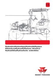
<strong>Service</strong> <strong>information</strong>B 0 4 20 8 73<strong>BIO</strong> <strong>Bale</strong> <strong>processor</strong>B 0 419 373Chamber full sensor In6<strong>Subject</strong>: Net knife sensor In5<strong>Electronics</strong>Net binding actuator sensor In3Prestretcher ring safe sector sensor In25 Automatic disengagement of PTOThe electronic control system of the <strong>BIO</strong> bale <strong>processor</strong> includes a function of automaticdisengagement of PTO of the tractor. When baling chamber is opened in order to start thewrapping sequences, a signal is produced by the system. By means Comm. cable of a relay and adaptedconnectors and wirings on the tractor, the PTO powered drive is disengaged by theelectrical operated clutch. Due to safety reasons it should notPowerbe possiblesupply cableto automaticallyreconnect the PTO.brownbrownVK2-2VK2-1blueVK1-2VK1-1bluebluebrownVK2-3brownVK1-3yell/gryell/grbrown blue yell/grbrown blue yell/grbrown blue yell/grbrown blue yell/grTop section closed sensor In11Lower section closed sensor In10Film cutter closed sensor In9Not in use In8Prestretcher ring positioning sensor In7Net feeding roller sensor In4Emergency stop switch In1Net actuatorRing rotationPick-upCrop knivesTop sectionBottom sectionFilm cuttersPTO clutchBrown PC-1Blue PC-2Brown VK1-1 plus rowYellow/green VK2-1 plus rowBlue VK1-3 minus rowBrown out12 minus rowBlue out11 plus rowYellow/green out11 minus rowBrown out10 minus rowBlue out9 plus rowYellow/green out9 minus rowBrown out8 minus rowBlue out7 plus rowYellow/green out7 minus rowBrown out6 minus rowBlue out5 plus rowYellow/green out5 minus rowBrown out4 minus rowBlue out3 plus rowYellow/green out3 minus rowBlue out1 plus rowYellow/green out1 minus rowOn output terminals OUT1 you will have 12V-power supply. In themoment the chamber top section starts opening and ”Top sectionclosed” sensor has lost its signal, a timer starts running. This timer isset in Dealer menu 2.When the time is completed, power on output OUT1 is switched off. The loss of powershould control a relay, which is activating the clutch control on the tractor. The power isswitched off for 10 sec., which is sufficient to make sure that any electronic clutch controlsystems is not reset without physically operating the clutch switch twice (once for resettingthe system, second time for restarting the PTO).The recommended timer value for automatic PTO stop (Dealer menu 2) is 2.5 sec.Issue: 1.1, November 2001For internal training and service purposes only Page 32 of 35©Kverneland Nærbø AS
<strong>Service</strong> <strong>information</strong><strong>BIO</strong> <strong>Bale</strong> <strong>processor</strong><strong>Subject</strong>: <strong>Electronics</strong>5.1 Connecting the automatic PTO stop5.1.1 PrincipleBDRP1TP2CCESTractor items:T = TractorC = PTO clutchE = Clutch electronicsS = Clutch controlC = Contact<strong>BIO</strong> items:B = Black box <strong>BIO</strong>D = Driver moduleR = RelayP1 = PlugAdditional items:P2 = Blind plug30 86 85 87 87AMaterials required:• 1 pcs. Single relay (w/terminals 87 & 87A)• Terminal connectors• Cable 2 x 2.5 mm 2• Two plugs and one contact for connecting machine system totractorAssembling tips:Check with the tractor distributor whether breaking off or closing the clutch circuit stopsPTO.The relay should be placed in the driver module box on the machine.P2Cconnected to the terminals of contact C.S2+-connection from clutch controlto clutch should be broken andconnected to contact C. Inorder to close this circuit whenbale <strong>processor</strong> is notconnected, the blind plug P2should be fitted, or a switchcontrolled circuit S2 should beIssue: 1.1, November 2001For internal training and service purposes only Page 33 of 35©Kverneland Nærbø AS
<strong>Service</strong> <strong>information</strong><strong>BIO</strong> <strong>Bale</strong> <strong>processor</strong><strong>Subject</strong>: <strong>Electronics</strong>If a broken circuit stops the PTO, relay should be connected as described here:30 = +-connection from PTO switch87 = +-connection to clutch (normally over a fuse)86 = +-connection from the driver module’s output OUT1 of <strong>BIO</strong>85 = – -connection from the driver module’s output OUT1 of <strong>BIO</strong>87A = not in useIf a closed circuit stops the PTO, relay should be connected as described here:30 = +-connection from PTO switch87A = +-connection to clutch (normally over a fuse)86 = +-connection from the driver module’s output OUT1 of <strong>BIO</strong>85 = – -connection from the driver module’s output OUT1 of <strong>BIO</strong>87 = not in useThe electric/electronics of the tractor might require different wirings. Check with the tractordistributor.5.1.2 Connecting tips for specific tractor models5.1.2.1 Valtra models with external emergency PTO stopfunctionPosition the relay on the machine (in the driver module box). Connect the tractor wire toterminal 30 & 87 and to a plug that fits the emergency PTO stop contact of the tractor.Remove the emergency PTO stop device and plug in the clutch control.For models 6000-8400 without this feature, a retrofit kit is available from the tractordistributor.5.1.2.2 New Holland M60 & TM+-connection from clutch switch to clutch control unit should be cut off and connected to therelay on the <strong>BIO</strong> by means of the contact and external wirings.30 = – -connection to PTO clutch switch (orange/lilac in multi plug of clutch switch)87 = – -connection from EMU switch (orange/lilac in multi plug of clutch switch)86 = +-connection from the driver module’s output OUT1 of <strong>BIO</strong>85 = – -connection from the driver module’s output OUT1 of <strong>BIO</strong>87A = not in use5.1.2.3 New Holland TL, TS & 40 series+-connection from clutch switch to clutch control unit should be cut off and connected to therelay on the <strong>BIO</strong> by means of the contact and external wirings.30 = + -connection to PTO clutch switch87 = + -connection from PTO clutch fuse86 = +-connection from the driver module’s output OUT1 of <strong>BIO</strong>Issue: 1.1, November 2001For internal training and service purposes only Page 34 of 35©Kverneland Nærbø AS
<strong>Service</strong> <strong>information</strong><strong>BIO</strong> <strong>Bale</strong> <strong>processor</strong><strong>Subject</strong>: <strong>Electronics</strong>85 = – -connection from the driver module’s output OUT1 of <strong>BIO</strong>87A = not in useIssue: 1.1, November 2001For internal training and service purposes only Page 35 of 35©Kverneland Nærbø AS