PDF Datasheet - Axiomatic Technologies Corp.
PDF Datasheet - Axiomatic Technologies Corp.
PDF Datasheet - Axiomatic Technologies Corp.

Create successful ePaper yourself
Turn your PDF publications into a flip-book with our unique Google optimized e-Paper software.
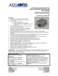
Technical <strong>Datasheet</strong> #TD1105AXCONNECTOR AMPLIFIERFOR PROPORTIONAL VALVES(0-5V/0-20mA/10K Potentiometer Inputs)Part No.: CAPV-H-5V-x complete with cable CAPV-6C-yMWhere:x = maximum current output (2A, 1.2A or 600mA)y = cable length (2 meters is the standard length)Function: The connector amplifier supplies a solenoid valve with currentproportional to an input control (voltage, 0-20mA, potentiometer or pre-set level).Features:• Maximum current adjustment does not affect minimum current setting• Adjustments accessible with a removable cover• Broad range of supply voltage (9 to 28VDC) with no degradation in performance• Current sensing circuit maintains output current regardless of changes in input voltage andcoil resistance• Modern technology utilizing high frequency switching output (PWM)• Energy efficient design (no heat sink is required)• Simple control with a 10K Potentiometer or sophisticated control with 0-5VDC or 0-20mAsignal inputs• Options for current output include 2A, 1.2A or 600mA• Simple implementation of “soft shift” control with minimal external components• Mates to a DIN 43 650 plug on a cartridge or block style solenoid valve• Electronic limiting circuit means no internal fuses• Short circuit proof (in case of solenoid failure or miswiring)• Reverse polarity protection• 2 m cable, 6 conductor, unterminated• Can disconnect load while connector amplifier is powered (“Hot Swap”)• CE certified for EMCApplication: Accurate control of hydraulic and pneumatic proportional solenoidvalves used in mobile construction equipment and industrial processes.1.0 Introduction:The User Guide for the connector amplifier describes the installation, set upadjustments and use of the unit with proportional solenoids.www.axiomatic.com
1.1 Description:The Connector Amplifier simplifies control of proportional solenoids by supplying a currentproportional to an input control (0-5V or 0-20mA or 10K potentiometer or pre-set level). It acceptspower supply voltages from 9 to 28VDC. This linear solenoid driver utilizes high frequencyswitching output (PWM) to provide a DC current output. The options for current output include 2A,1.2A or 600mA. A current sensing circuit maintains output current regardless of changes in inputvoltage and coil resistance. The user can adjust maximum and minimum current, ramp times,dither frequency, and amplitude to match the application. The unit is available with a DIN 43650connection to mount directly on the coil. Other versions are available with 4-20mA or 0-10Vinputs. A remote mount version is housed in a rugged metal box.TD1105AX 2
1.2 Technical Specifications:All specifications are typical at nominal input voltage and 25°C unless otherwise specified.General SpecificationsOperating conditions-40 to +85°C (-40 to 185°F)Storage temperature-50 to 125°C (-58 to 257°F)Electromagnetic compatibility (EMC) Emission EN 50081-2Immunity EN 50082-2ApprovalsCEPackaging, Cable andHousing:Electrical connectionsHirschmann GDME 2011 black housing (PA material, 94 V1),central screw M3 x 40, transparent cover, washer and o-ring,nitrile rubber gasketDIN 43650-A contact arrangement with 18 mm spacing(plug-style to mount on valve)Contacts: Sn, PA, 94V1Approvals: VDE, SEV, GL(A version for remote mounting is also available.)Cable:2 metre cable, 6 conductor, unterminated, 18 AWGFor pin out, refer to Section 3.3.Manufacturer: Phoenix EDT Inc. P/N: D0518006-8Conductors: Stranded, tin-plated copperJacket: PVCInsulation: SR-PVCCable Markings: UL AWM, CM, CSA AWM II A/B, CMG FT4Protection classIP65 when correctly installed with lid, compressionwasher, o-ring and base gasketDimensions in mm/inches(excluding cable)Length L1 85.35mm 3.36”L2 61.75mm 2.43”L3 34.00mm 1.34”Width = L3 34.00mm 1.34”Height H1 38.00mm 1.49”Electrical SpecificationsOperating voltage (power supply requirement)Control input signal optionsInput resistanceRange of maximum output currentSolenoid resistance9 to 28 VDC power supply rangeAccepts up to a maximum of 32 VDC0-5 VDC voltage signal or0-20 mA current signal or10K Potentiometer (accepts 2.5K to 50K pots) orfor soft shift control, pre-set the connector amplifier by connecting+5VDC to input and using the I max adjustment(4-20mA or 0-10VDC input versions are also available.)Voltage mode: 125K OhmsCurrent mode: 50 Ohms2A (1.2A or 600mA versions available)R coil < (V power supply - 1.5 V)/I maxInternal supply for setpoint potentiometer+5VDCNote 1: Match power supply voltage with rating of solenoid coil. Operating the amplifier with a supply voltage lower thanthe solenoid rated voltage may result in reduced maximum current output.Note 2: The coil should have no polarity or protection diodes for proper operation of the device.Note 3: The maximum current output of the amplifier should not exceed the current rating of the solenoid coil.TD1105AX 3
Input Option 4 - Soft Shift - 2 Directions, Hi-Lo ControlMaximum current, minimum current and ramp times (for shift time) are set once for theappropriate function of the proportional solenoid valve. These settings for high, low and off makesoft shift possible between the high and low settings. A two-position switch or relay contact cancontrol the input.Input Option 5 - Soft Shift - One Direction OnlyFactory wired inputs mean that only 2 wires go to the solenoid valve. Maximum current is set tocontrol the input current and the ramp time setting is used for soft shift (on only).More sophisticated control can be achieved by linking the connector amplifier to a programmablelogic controller (PLC) or other control systems.TD1105AX 5
3.0 Installation Procedures:3.1 Precautions Against Leaks From The EnvironmentEnsure the transparent lid is firmly in place.Ensure the brown rubber base gasket is in place, providing a seal between the connectoramplifier and the plug on the valve.The mounting screw with o-ring and washer in place should be flush with the top of the lid andfastened in place. Tighten the screw to make a firm connection to the valve with a Phillips #2screwdriver.3.2 Necessary Equipment• Connector Amplifier for Proportional Valves• Cartridge or Block Proportional Solenoid Valve ready to accept a DIN 43650 plug• Hydraulic power source and load circuit• Power Supply (9 to 28 VDC)• DC voltmeter (optional)• Choice of Inputs: 10K potentiometer or 0-5VDC voltage signal or 0-20mA current signal• External fusing recommended (3A)TD1105AX 6
3.3 Installation Steps• Supply voltage should be between 9 and 28 VDC. Excess voltage will damage the connectoramplifier. Match the power supply voltage with the voltage rating of the solenoid coil.Operating the amplifier with a supply voltage lower than the solenoid rated voltage may resultin reduced maximum current output.• The maximum current output of the amplifier should not exceed the current rating of the solenoid coil.• The coil should have no polarity or protection diodes for proper operation of the device.• Do not install the connector amplifier near high voltage relays or other sources of electricalinterference.• Connect the power supply, command potentiometer or signal input and valve solenoid asshown below and in Section 3.4. Put isolation sleeves on any unused wires for input signalor potentiometer.• Set the input signal to the maximum level and confirm it is operating properly.TD1105AX 7
3.4 Wiring ConnectionsConnect the cable conductors to the power supply and input signal or potentiometer as follows.For Potentiometer, 0-20mA or 0-5VDC Control:Turn ramp screws fully counterclockwise to eliminate ramping.Use I-Min. screw to set up minimum speed with minimum control input.Use I-Max. screw to set maximum speed with 100% of control input.4.0 Set Up Adjustment Procedures:The location of the trim pots for the set up adjustments is shown in Section 3.3.WARNING: The operator must ensure that the operation of the valve within the full scale ofthe control function will not cause hazards, while performing set up adjustments to the connectoramplifier.4.1 PreparationEnsure that the connector amplifier is connected to an operating proportional valve.Use a small screwdriver to loosen the mounting screw and remove the transparent lid.The trim pots are adjusted with a jeweler’s sized screwdriver (slotted 1.5).4.2 Interaction Between Maximum and Minimum Current AdjustmentsAdjusting the maximum current (I max ) does not affect the minimum current (I min ) setting.TD1105AX 8
Adjusting the minimum current will shiftthe maximum current setting, asshown.4.3 Connector Amplifier SettingsThe following settings represent a typical set up for a voltage or current signal input operatingscenario. Conditions will vary for other set up scenarios. I min and I max are multi-turn trim potswith a range of 10 turns. Use a slotted 1.5 screwdriver.Trim Pot Adjustments Range of Adjustment Factory SettingZero - Minimum Current Setting (I min ) 0 to 0.5 A (for 2 A output model)0 to 0.3 A (for 1.2 A output model)0 to 150 mA (for 600 mA output model)0% (CCW)Span - Maximum Current Setting(I max )0.6 to 2.0 A* (for 2 A output model)0.36 to 1.2 A (for 1.2 A output model)180 to 600 mA (for 600 mA outputmodel)100% (CW)Ramp Time (Rising and Falling Edge) 0.01 to 5 seconds independent minimum (0.01seconds) (CCW)**Dither Level (Amplitude) 0 to 10% of rated maximum current 0% (CCW)Dither Frequency 70 to 350 Hz (±10%) minimum (CCW)CW = clockwise, CCW = Counterclockwise∗NOTE 1: Range of maximum output current is 2A (maximum output current = minimum current setting + maximumcurrent setting)**NOTE 2: To eliminate ramping, turn the trim pots fully counterclockwise.TD1105AX 9
Setting the Minimum Current (I min )• Set the minimum current before setting the maximum current.• Apply minimum input (control potentiometer at minimum or 0V or 0A).• The factory setting for the I min trim pot is 0 or fully counterclockwise (CCW).• If the desired minimum current is greater than 0, adjust the trim pot clockwise (CW) until thedesired current is achieved.The minimum current setting can be used to take into account the mechanical valve deadbandand provide desired offsets from zero to allow full control within the functional range of thespecific valve.Setting the Maximum Current (I max )• Apply maximum control (control pot at maximum or 5V or 20 mA).• The factory setting for the I max trim pot is 100% or fully CW.• Turn the trim pot CCW to adjust the current setting downwards to the desired maximum.The maximum current setting is adjusted to meet the customer’s working pressure or flow rangeto the full scale signal input range. This provides maximum control for a specific application.Setting the Ramp Times• The factory setting for ramp times is the minimum (0.01 seconds) or fully CCW.• If the ramp time settings are not needed, leave the setting at the minimum value.• To change the ramp times, adjust the trim pot CW to increase the time.• Note that rising and falling ramp times are independent.Ramp times are application dependent. They limit the rate of change or how fast the operationhappens. Note that if the input signal is not applied long enough for the ramp time set, thedesired solenoid current will not be reached.Setting the Dither Amplitude• The factory setting for dither amplitude is 0% (CCW).• To adjust dither amplitude, turn the trim pot CW until small changes in the input signalregister an immediate response in the valve.• Choose the smallest effective dither amplitude.Dither amplitude is adjustable from 0 to 10% of the rated maximum current. Dither amplitude andfrequency are dependent on the specific valve. The effects of static friction on the operation ofthe solenoid are reduced by the application of a small AC current. The hysteresis andrepeatability of the valve are improved by this practice. The optimum dither amplitude is attainedwhen small input signal changes register an immediate response in the valve (pressure or flowthrough the valve).TD1105AX 10
Setting the Dither Frequency• The factory setting for dither frequency is the minimum or 0% (CCW).• To adjust dither frequency, turn the trim pot CW until the desired frequency is set.• Refer to the proportional valve manufacturer’s catalogue for the dither frequency rating of aparticular valve.5.0 Start Up Procedures:A typical start up procedure is as follows:1. Ensure the lid, compression washer, o-ring and base gasket are correctly in place (necessaryfor IP65 protection).2. Ensure that no damage or injury can occur on the machine when the valve is operated.3. Attach the connector amplifier to the load.4. Switch on the power supply to the connector amplifier and apply a control signal.Successful completion of these four steps means the connector amplifier and load are ready fornormal use.6.0 Operation:The connector amplifier ensures a hydraulic proportional valve will function in a manner directlyproportional to the control input. Accurate and repeatable operation is attained. Simple controlcan be achieved with a 10K Potentiometer powered by the connector amplifier’s internal +5VDCpower supply. More sophisticated control of the hydraulic valve occurs with 0-5VDC or 0-20mAsignal inputs.The connector amplifier performs within the mechanical limits of the proportional valve. Nomaintenance of the unit is required.7.0 Repair/Replacement:The connector amplifier contains no serviceable components. Please do not disassemble theunit. Tampering will void the product warranty. The product will be replaced or repaired on a“return to factory” basis. The warranty is found at www.axiomatic.com/service.html.8.0 Ordering Part Number:Connector AmplifierCAPV-H-5V-x complete with cable CAPV-6C-yMWhere:x = maximum current output (2A, 1.2A or 600mA)y = cable length (2 meters is the standard length)Form: TD1105AX-06/17/11TD1105AX 11