Dressler ARA-2000 active antenna - DD1US
Dressler ARA-2000 active antenna - DD1US
Dressler ARA-2000 active antenna - DD1US
- No tags were found...

You also want an ePaper? Increase the reach of your titles
YUMPU automatically turns print PDFs into web optimized ePapers that Google loves.
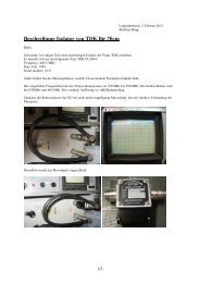
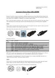
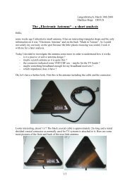
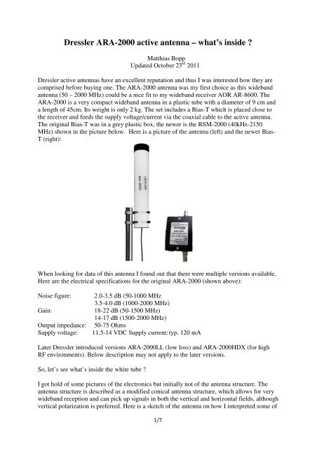
<strong>Dressler</strong> <strong>ARA</strong>-<strong>2000</strong> <strong>active</strong> <strong>antenna</strong> – what’s inside ?Matthias BoppUpdated October 23 rd 2011<strong>Dressler</strong> <strong>active</strong> <strong>antenna</strong>s have an excellent reputation and thus I was interested how they arecomprised before buying one. The <strong>ARA</strong>-<strong>2000</strong> <strong>antenna</strong> was my first choice as this wideband<strong>antenna</strong> (50 – <strong>2000</strong> MHz) could be a nice fit to my wideband receiver AOR AR-8600. The<strong>ARA</strong>-<strong>2000</strong> is a very compact wideband <strong>antenna</strong> in a plastic tube with a diameter of 9 cm anda length of 45cm. Its weight is only 2 kg. The set includes a Bias-T which is placed close tothe receiver and feeds the supply voltage/current via the coaxial cable to the <strong>active</strong> <strong>antenna</strong>.The original Bias-T was in a grey plastic box, the newer is the RSM-<strong>2000</strong> (40kHz-2150MHz) shown in the picture below. Here is a picture of the <strong>antenna</strong> (left) and the newer Bias-T (right):When looking for data of this <strong>antenna</strong> I found out that there were multiple versions available.Here are the electrical specifications for the original <strong>ARA</strong>-<strong>2000</strong> (shown above):Noise figure:Gain:Output impedance:Supply voltage:2.0-3.5 dB (50-1000 MHz3.5-4.0 dB (1000-<strong>2000</strong> MHz)18-22 dB (50-1500 MHz)14-17 dB (1500-<strong>2000</strong> MHz)50-75 Ohms11.5-14 VDC Supply current: typ. 120 mALater <strong>Dressler</strong> introduced versions <strong>ARA</strong>-<strong>2000</strong>LL (low loss) and <strong>ARA</strong>-<strong>2000</strong>HDX (for highRF environments). Below description may not apply to the later versions.So, let’s see what’s inside the white tube ?I got hold of some pictures of the electronics but initially not of the <strong>antenna</strong> structure. The<strong>antenna</strong> structure is described as a modified conical <strong>antenna</strong> structure, which allows for verywideband reception and can pick up signals in both the vertical and horizontal fields, althoughvertical polarization is preferred. Here is a sketch of the <strong>antenna</strong> on how I interpreted some of1/7
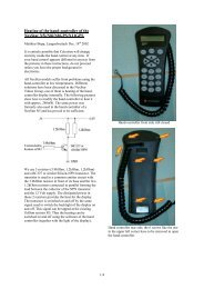
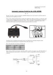
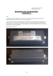
Here is the first version I am aware of. The pictures were provided by Walter DO7WW. Itconsists of 2 MMICs amplifiers which are cascaded. The type of the MMICs are not 100%know to me but most likely they are Avantek (today Avago) MSA-1105 Si-MMICs. Thespecification, package type and marking (Top A, bottom H) support this assumption.3/7
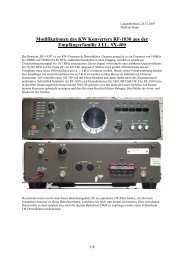
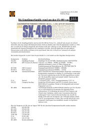
The MSA-1105 MMIC is a high dynamic range 50 Ohm or 75 Ohm gain block with a 3dBbandwidth of 50 MHz to 1.3 GHz. The 1dB compression point at 500 MHz is P1dB=17.5dBm. The typical noise figure at 500 MHz is 3.6 dB. The package is a “05” surface mountplastic package:The circuit in the <strong>ARA</strong>-<strong>2000</strong> is identical to the typical application circuit as proposed byAvantek.Here are the key data of this MMIC:4/7
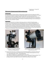
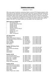
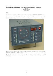
Here are 2 pictures of a second version I am aware of.The <strong>active</strong> section is based on a MMIC (Monolithic Microwave Integrated Circuit) widebandamplifier from RFMD in a SOIC-8 package. The RF2312 is a wideband amplifier originallytargeting the TV market. It includes a preamplifier with a low noise figure followed by a highcurrent final stage for maximum strong signal handling performance. Input and outputimpedances are optimized to 75 Ohms.Here are some of the specifications of this MMIC RF2132:Frequency Range: 0-2500 MHzGain typ. 16 dB @ 900 MHzNoise Figure typ. 3.8 dB @ 50-300 MHztyp. 4.2 dB @ 300-1000 MHzOIP3 typ. 38 dBm @ 100 MHztyp. 36 dBm @ 500 MHztyp. 30 dBm @ 900 MHzAs you can see, the specs of the complete <strong>active</strong> <strong>antenna</strong> are more aggressive than those of theMMIC itself. Maybe <strong>Dressler</strong> selected special ICs with higher specs? I doubt it …5/7
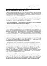
Here is a basic application circuit as proposed by RFMD:The actual circuit on the PCB (see picture below) is very similar to the test circuit above. Thebias input P1-1 is connected to the N-jack for remote bias operation (phantom feed). Theinput of the MMIC is protected against overloading by strong low frequency signals by asimple high pass filter (lower left structure in the picture below).6/7
As a summary I have to state that am a bit surprised about the very simple construction of this<strong>antenna</strong>. I would expect a very limited large signal handling capability and wonder why this<strong>antenna</strong> has such a positive reputation.Maybe this is simply the case because it is very easy to mount and operate. In any case the<strong>ARA</strong>-<strong>2000</strong> offers a very important advantage over any passive <strong>antenna</strong> systems: the low noiseamplifier in the <strong>antenna</strong> increases the signal before cable losses are degrading the signal tonoise ratio. Depending on the cable length used, the additional improvement in reception canbe significant.The production of this <strong>antenna</strong> has been discontinued anyhow and this little description isintended to provide some background information for those who consider buying one secondhand, who need to repair their <strong>antenna</strong> or are interested to build one themselves.I am always happy to answer questions. Please direct them to my Email address given below.Best regardsMatthiasEmail: dd1us@amsat.orgHomepage: www.dd1us.de7/7