GRASOL ROOF MOUNTING SYSTEM INSTALLATION ... - Solar360
GRASOL ROOF MOUNTING SYSTEM INSTALLATION ... - Solar360
GRASOL ROOF MOUNTING SYSTEM INSTALLATION ... - Solar360

You also want an ePaper? Increase the reach of your titles
YUMPU automatically turns print PDFs into web optimized ePapers that Google loves.
<strong>GRASOL</strong> <strong>ROOF</strong><strong>MOUNTING</strong> <strong>SYSTEM</strong><strong>INSTALLATION</strong> Manual
Solar Roof Mounting System Installation ManualContentsChapter Title Page1 General information 32 Safety and Installer Responsibilities 43 Technical Specifications 54 Tools for Installation 65 Components Description 76 System overview 97 Designing the module field 108 Code-compliant AS/NZS 1170 planning 119 Installation 1510 Warranty 21Published Date 2012‐03‐07 2 / 21
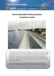
Solar Roof Mounting System Installation Manual1. General informationThank you for choosing the Grace solar roof mounting system. Made from custom-built aluminum extrusionsand components, Grace Solar’s innovated design and improved frame strength greatly simplify solar panelinstallation. The easy installation four steps make the Tilt-in modules can be put into the GR Rail on anyposition quickly. So, the Tilt-in modules is pre-assembly with the clamp to save your install time.Easy installation four stepsGrace solar’s versatile design makes it suitable for a wide variety of building types and zones includingresidential, commercial and remote environments.Gracesolar is backed by a 10-year warranty and is compliant with the Australian/New Zealand Standard onWind Actions (AS/NZS1170.2.2011).Published Date 2012‐03‐07 3 / 21
Solar Roof Mounting System Installation Manual2. Safety and Installer ResponsibilitiesCautionInstallation of thisproduct is to beperformed only byprofessionallytrained installers.Any attempt by anunqualified personto install thisproduct couldresult in death orserious injury.2.1 Handling and Installing Grace solar ››»It is critically important that safety practices are observed when installing Do not throw or roughly handle any Grace solar components. Do not bring Grace solar system into contact with sharp or heavy objects. Do not modify Grace solar components in any way. The exchange of bolts,drilling of holes, bending or any other physical changes not described instandard installation procedure will void the warranty. It is the installer’s responsibility to verify the integrity of the structure towhich Grace solar components is fixed. Roofs or structures withrotten/rusted bearers, undersized bearers, excessively spaced bearers,or any other unsuitable substructure cannot be used with Grace solarcomponents, and installation on such structures will void the warranty,and could result in death or serious injury.2.2 Wind and Climate DesignAS/NZS1170.2.2011 provides guidance on determining the wind pressuresapplicable to your Grace solar system install site, taking into account roofshape and geographic location. Sufficient guidance is given in this document,but you may wish to procure a copy of these standards if your companyinstalls Australia/New Zealand wide. REMEMBER average wind speeds are higher for structures mountedcloser to the roof perimeter zone (edge). Refer to ‘Fixing within RoofInstallation Zone’ for more information) Make sure your installation complies with local and national buildingcodes. Take into account relevant design parameters (wind speed,exposure and topographic factor) when determining the loading for theinstallation. If alternative fasteners are used to ix the framing to the roof (assumingsupplied fasteners are unsuitable for any reason), all screw fastenersmust conform to corrosion resistance Class 4 Australian StandardAS3566 and be of equal or greater strength to those supplied with yourGrace solar system order.Published Date 2012‐03‐07 4 / 21
Solar Roof Mounting System Installation Manual3. Technical Specifications3.1 Applications Commercial and residential buildings Marine applications and remote areasCautionRefer to thesection “DesigningYour System”before attemptinginstallation. Failureto correctlyestablish therequirement of theproposedinstallation site isdangerous and willvoid the framingwarranty.3.2 Features 6005-T5 Aluminum extrusion Innovated designed of the Tilt-in modules, which can be pre-assemblywith the clamp, make the installation easy and quick. Suitable for difference conditions and the most solar panels at presentmarket. Significantly higher strength-to-weight ratio than other framing products,providing improved efficiency due to greater frame spans, inherentcorrosion resistance resulting in low ongoing maintenance and anextended product life. Complies with Australian/New Zealand Standard on Wind Actions,AS/NZS1170.2.2011 Anodized finish3.3 MaterialMaterialTensile strengthUltimateYield6005-T5 AluminumExtruded260MPa240MpaStainless Steel 304 635MPa 235MPaStainless Steel A2-70 700MPa 450Mpa3.4. Installation conditionRoof slope 0° to 60°Building heightUp to 20mMounting structureTimberRoof typesFlat or pitched steel and tileSystem angleFlushed with the roofNote: if the condition is over the table list, please contact us to confirm.Published Date 2012‐03‐07 5 / 21
Solar Roof Mounting System Installation Manual4. Tools for InstallationThe following tools are required for the installation: 6 mm Allen key or hexagonal driver bit.If using a 6mm driver bit, make sure the cordlesspower tool used for the driving has a hand-tightclutch setting a fine (soft) impact drive to preventdamage to the fragile glass panels and threads onthe Structure. Cordless drill;Drill or impact driver for driving roof material fixingsAngle grinder;For terracotta tile roof installation, and angle grinderfitted with a continuous edge diamond tippedtile0cutting blade; gloves, hearing protection, a faceprotection mask, and a suitably rated breathingprotection mask for all people in proximity ofgrindingGloves;Protect the hazard of the sharp corners.Cord or color pen;Mark the installation position;Spirit levelRuleIf necessary, timber to shim the roof hooksPublished Date 2012‐03‐07 6 / 21
Solar Roof Mounting System Installation Manual5. Components DescriptionGR Rail hold each panel row length can be customized 6005-T5 extruded aluminumStandard Rail Length808~826mm wide 990~1020mm wide panelspanels2560mm3405mm4200mmGR Rail Splice Kit Extend GR Rail to any length as required by thequantity or width of the solar panelsInter Clamp Kit for Framed Modules Fit between two panels Fastened with a 6mm Allen key Standard pre-assembly for the usual panels withthickness 30, 35, 40, 46, 50, 57mmEnd Clamp Kit for Framed Modules Hold the edge of each end panels Fastened with a 6mm Allen key Standard pre-assembly for the usual panels withthickness 30, 35, 40, 46, 50, 57mmAdjustable End Clamp Kit Hold the edge of each end panels Fastened with a 6mm Allen key Adjustable for the panels with thickness from25~60mmPublished Date 2012‐03‐07 7 / 21
Solar Roof Mounting System Installation ManualVariety of Roof HookStainless Steel Roof Hook 1 # Fix to the rafter below Roman tile roof Include 3pcs st6.3x80 wood screwsStainless Steel Roof Hook 2 # Fix to the rafter below flat tile roof Include 2pcs st6.3x80 wood screwsStainless Steel Roof Hook 3 # Side fix to the rafter below Roman tile roof Include 3pcs st6.3x80 wood screwsStainless Steel Roof Hook 4# Fix to the rafter on slate tile roof Include 3pcs st6.3x80 wood screwsAluminum Tin Roof Hook 5# Fix to the purlin on tin roof Include 1pcs st6.3x80 wood screwsStainless Steel Roof Hook 6# Fix to the rafter below Roman tile roof Include 3pcs st6.3x80 wood screwsAccessoriesGrounding Clip Installed under two panels Stainless Steel 304Grounding Lug Aluminum Lay-in lug to connect wires Pre-assemblyCopper Grounding Lug Copper Lay-in lug to connect wires Pre-assembly Excellent electric conductivityPublished Date 2012‐03‐07 8 / 21
Solar Roof Mounting System Installation Manual6. System overviewAll components of the system are listed below. The version and quantities of the parts can vary, depending of• Type of roof • Type of module• Number of modules • Site specifics1 GS Rail3 Inter Clamp5 Roof hook2 GS Rail Splice4 End ClampPublished Date 2012‐03‐07 9 / 21
Solar Roof Mounting System Installation Manual7. Designing the module fieldBelow, the distances between roof connections for a portrait installation are specified. Clamp-on roof hooksneed to be installed in specific distances, depending on the distance of rafters and the stoical conditions.1. Height of the module field: module height x number of modules vertically2. Width of the module field: number of modules horizontally x (width of the module + 18 mm)+32 mm3. Distance between roof connections vertically (according to the clamping points pre-defined by the moduleproducer): Quarter-points of the modules, about 1/2 of module height.4. Distance between roof connections horizontally: Depending on the distance between rafters and on thestatic requirements (please see the Chapter 8 on page 11).5. Distance between modules: 17 mmWhen positioning the modules, please take into consideration• That the values above are• That dimensions of tiles or other roof covering and the position of the rafters define the precise actualhorizontal distance between roof connections• That the distance between roof laths defines the precise actual vertical distance between roofconnections.Published Date 2012‐03‐07 10 / 21
Solar Roof Mounting System Installation Manual8. code-compliant AS/NZS 1170 planning8.1 Determine the wind region of your installation siteRegion Definition:Wind regions are pre defined for all of Australia by Australian Standard 1170. The Wind Region has nothingto do with surrounding topography or buildings.• Most of Australia is designated Region A which indicates a Regional Ultimate Basic Wind Velocity of45msec.• Some areas are designated Region B (57msec). Local authorities will advise if this applies in your area.• Region C areas (66msec) are generally referred to as Cyclonic and are generally limited to northerncoastal areas. Most Region C zones end 100km inland.• Region D (80msec) Australia's worst Cyclonic Region between Carnarvon and Pardoo in WesternAustralia.8.2. Determine the height of the of your installation siteThis document provides sufficient information for Grace solar system installation height less than 20meters. If your installation site is more than 20 meters in height, please contact Grace solar to obtainengineering data to support your installation.Published Date 2012‐03‐07 11 / 21
Solar Roof Mounting System Installation Manual8.3 Determine Roof Installation Roof AreasGrace solar system can be installed anywhere on a roof but fixing centers are required to be reduced atridges and edges. The diagram below shows the area of higher wind loadings within 0.2A and 0.2Bof aroof edge ridge (where A and B are the planned dimension of the building).Center ZoneEdge ZoneThe following table will help you determine the maximum rail support spacing for your project.Also note that if the roof slope is less than 10 degree the reduction on spacing does not apply.Published Date 2012‐03‐07 12 / 21
Solar Roof Mounting System Installation Manual8.4 Determine the Maximum Rail Support Spacinga. Please use the following table to determine the GR Rail support spacing for tile roof installations.1970mm Long Panels fixed to Tiled RoofInstallationHeightRegion A (mm) Region B (mm) Region C (mm) Region D (mm)Max area ofone panel3.0m 2 2.5m 2 2.0m 2 1.5m 2Roof AreaCenter Edge Center Edge Center Edge Center EdgeZone Zone Zone Zone Zone Zone Zone Zone5 Meters 2130 1500 1690 1200 1380 980 108010 Meters 1940 1370 1540 1090 1260 890 99015 Meters 1840 1230 1460 980 1190 800 94020 Meters 1740 1380 1130 890 The above figures are based on modules lengths of up to 1970mm, maximum weight of 15Kg/m 2 1650mm modules requires 2 rails with fixing as per table above The above spacing applies for fixing through thin sheet purlins (greater than 1.0mm thickness) or aminimum embedment of 50mm into timber purlins. Tile brackets should fixed to the rafter using two 12g mounting screws (M6x80mm) For 35mm embedment into timber of fixings into 0.55mm thickness steel for regions A+B remainunchanged. For regions C reduce the spacing by 15%. For region D reduce the spacing by 35%. In case the wooden rafters/trusses you wish to mount on are too thin and the screws would be tooclose to the edge of the rafters please pre-drill with a 3~4mm drill in order to avoid the splitting of thetimber ( or use the side mount roof hook).b. Please use the following table to determine the base rail support spacing for Tin roof installations.1970mm Long Panels fixed to Tin RoofInstallationHeightRegion A (mm) Region B (mm) Region C (mm) Region D (mm)Max area ofone panel3.0m 2 2.5m 2 2.0m 2 1.5m 2Roof AreaCenter Edge Center Edge Center Edge Center EdgeZone Zone Zone Zone Zone Zone Zone Zone5 Meters 2130 1110 1390 690 940 470 58010 Meters 1940 1010 1270 630 860 430 53015 Meters 1840 950 1200 590 810 400 50020 Meters 1740 1140 770 470 The above figures are based on modules lengths of up to 1970mm, maximum weight of 15Kg/m 2 1650mm modules requires 2 rails with fixing as per table above The above spacing applies for fixing through thin sheet purlins (greater than 0.75mm thickness) or aminimum embedment of 50mm into timber purlins.Published Date 2012‐03‐07 13 / 21
Solar Roof Mounting System Installation ManualThe L Feet should be fixed to the purlins under using one 12g mounting screw (M6x80mm) throughsheet metal roofs with desk rubber.For 35mm embedment into timber of fixing into 0.55mm thickness steel the max panel length shouldbe reduced to 1700mm and the max spacing reduced by 20%.Please note that the screws provided with our products are designed for mounting into woodenstructures.8.5 Verify acceptable Rail End OverhangRail End Overhang must equal 50 percent or less of foot spacing. Thus, if foot spacing is 1200mm, theRail End Over hang can be up to 600mm. In this case, two feet can support a rail of as much as 2400mm(1200mm between the feet and 600mm of overhang at each end).8.6 Determine Roof slopeGrace solar system can be used for roof slope up to 60 degrees. Please verify the Installation site roofslope should be between 0 degrees and 60 degrees.Published Date 2012‐03‐07 14 / 21
Solar Roof Mounting System Installation Manual9. InstallationInstall on Roman Tile Roof1. Remove the roof tiles at the markedpositions or simply lift them up slightly.2. Input the roof hook to the woodenbeam. Fix the roof hooks with 3xwood screws (M6x80).3. Cover the hooks by the removed tile4. The roof hook must not press againstthe roof tile. Place it flat. If necessary,shim the roof hook with wood.5. If necessary, use an angle grinder orhammer to cut a concavity in the tilethat covers the roof hook at the pointwhere the roof hook comes through.(Caution! Must not use fixed roof hookas a ladder, as this extreme point loadcould damage the tile below.WrongCorrectPublished Date 2012‐03‐07 15 / 21
Solar Roof Mounting System Installation ManualInstall on Plain Tile Roof6. Mark roof hook installation points,and cut recesses for hooks into plaintiles/slate at each installation point.7. Cut titanium zinc metal sheets to fitand install them under the roofhooks. Fix the roof hooks to therafter using two 6 x 80 mm woodscrews.Install on Tin Roof8. Mark roof hook installation pointsand use the power tool to drill thewood screw through the point tofasten the L feet with the purlin.Published Date 2012‐03‐07 16 / 21
Solar Roof Mounting System Installation ManualInstall The GS Rail9. Tilt-in module quick mount.Four steps to quick mount the tilt-inmodule into GS rail channel.Move the assembly toIt’s desired final position, andfastens firmly in place by torque boltto 10Nm.10. Connect the roof hook with the GSrail.a. Insert the tilt-in module into theside channel of the GS rail asthe step 9 shown.b. Adjust the GS rail to be level.c. Fasten the bolt.Published Date 2012‐03‐07 17 / 21
Solar Roof Mounting System Installation Manual11. GS Rail connectInstallation of the splice to connectmultiple rails together. Slide thesplice on the rear side of thepre-assembled rails. Fasten the firstbolt firmly. Then slide the next railinto the splice. When comestogether, fasten the other bolt. Theconnection is finished. An expansiongap at the rail joints is suggested.Leave a gap about a finger width.Install the module12. Installing anti-slip protectionThe anti-lip protection is onlynecessary on the lowermost row ofmodules. At first, fit two bolts M6*20and nuts into the lower holes ofeach module. Then place the firstmodule of the bottom row so thatthe anti-slip protection sits in the railchannel of the lowest row of rails13. Fixing the outer modules by Endclamp.a. Put the end clamp kit into thetop channel of the GS Rail asthe step 9.b. Push the side of module tofirmly against the end clampand then fasten the bolt.Published Date 2012‐03‐07 18 / 21
Solar Roof Mounting System Installation Manual14. Fixing the inter modules by interclamp.a. Put the inter clamp kit into thetop channel of the GS Rail asthe step 9.b. Push the Inter-module clampfirmly against the already fixedmodule.c. Push the next module againstthe other side of themodule-inter clamp.d. Tighten the bolt15. Installing the further rows ofmodulesPublished Date 2012‐03‐07 19 / 21
Solar Roof Mounting System Installation ManualCable tie and Grounding16. Tie cable with the raila. Tie the cable with the rail usingthe zip tieb. Using Plastic cable clip tomanage the cable.17. GroundingPlease see the Grace solarGrounding System InstallationGuidePublished Date 2012‐03‐07 20 / 21
Solar Roof Mounting System Installation Manual10. WarrantyXiamen Grace Solar Technology Co., Ltd. warrants that its Grace Solar Panel Mounting System is free from defectsin materials and workmanship for a period of 10 years from the date on which the Frame is purchased from GraceSolar, on the terms set out in this warranty.In the event that the Frame does not conform to this warranty during the Warranty Period, Grace Solar will, at itsoption, either repair or replace the Frame or pay the cost of having the Frame repaired or replaced. To the extentpermitted by law, Grace Solar‘s total liability under this warranty will in no circumstances exceed the repair orreplacement of the Frame or payment of the cost of having the Frame repaired or replaced. In the event ofreplacement of the Frame, any remaining part of the Warranty Period will be transferred to the replacementFrame.This warranty will not apply to any defect or damage to the Frame arising directly or indirectly from:1. Shipment or storage of the Frame;2. Improper installation, maintenance, repair or use of the Frame;3. Normal wear and tear;4. Misuse, neglect, abuse, accidental damage or modification to the Frame;5. Failure to observe the instructions set out in the System Manual; or6. Power failure, power surges, lightning, fire, explosion, flood, extreme weather conditions, environmentaldisasters or other causes outside Grace Solar’s control, as determined by Grace Solar in its sole discretion.This warranty does not cover, and under no circumstances will Grace Solar be liable for, any costs associated withthe removal, shipping, handling or re‐installation of the Frame or the costs of sending personnel to any site torepair or replace the Frame.This warranty is only provided to the original purchaser of the Grace Solar panels mounting system (Purchaser) or,where the Purchaser is an installer or builder who on‐supplies the Frame to another party, to that other party(End‐User). This warranty is not transferable.Where an End‐User wants make a claim under this warranty, the End‐User must in the first instance contact theinstaller or builder from whom the Frame was purchased.This warranty will not apply to any claims received by Grace Solar after the expiration of the Warranty Period.Grace Solar makes no warranties, express or implied, other than the warranties made herein, and specificallydisclaim all other warranties, representations and conditions to the extent permitted by law. To the extentpermitted by law, in no circumstances will Grace Solar be liable for direct, indirect, special or consequentialdamages arising from a defective Frame or for any damage or injury to persons or property. Grace Solar’saggregate liability, if any, in damages or otherwise, will not exceed the invoice value of the Frame at the time ofpurchase from Grace Solar.Any provision contained in this warranty which is prohibited or unenforceable in any jurisdiction will be deemed tobe ineffective to the extent of such prohibition or unenforceability and will not invalidate the remaining provisionsnor affect the validity or enforceability of that provision in any other jurisdiction.Published Date 2012‐03‐07 21 / 21