The Michelson Interferometer
The Michelson Interferometer
The Michelson Interferometer

You also want an ePaper? Increase the reach of your titles
YUMPU automatically turns print PDFs into web optimized ePapers that Google loves.
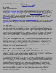
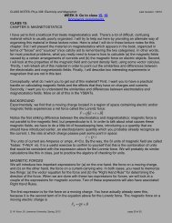
Phys 221L, Modern Physics Lab D. W. Koon, Fall 2013THE MICHELSON INTERFEROMETERBACKGROUND RESEARCHRead about the <strong>Michelson</strong>-Morley experiment. Find an equation that relates the [classically] predicted phase shift to theparameters of the interferometer. A good place to start to look for this information would be your textbook and othertextbooks. I will expect you to do this step in the future before the week’s lab.EXPERIMENT #1: GREEN- AND WHITE-LIGHT MICHELSON INTERFERENCE PATTERNSSTEP 1: ALIGN THE TWO MICHELSON INTERFEROMETER IMAGES• Mount a green laser as the source, with a lens in front that disperses thenarrow laser beam.• Adjust the two set screws on the back of the one mirror (the one that hastwo set screws on it) to align the reflections coming from the two separatemirrors. When they are close to exact alignment, you will start to see“pinstripes” in the green field of view. Adjust the set screws very gently andslowly!• Adjust the set screws until these stripes become wider. Keep going,alternating set screws as needed. If you’re lucky you may be able to turnthese stripes into the center of a bull’s eye pattern (with the concentriccircles getting closer as you move away from the center. Adjust thestripe/circles as best as you can to get the center of the bull’s eye.• Sketch and describe what you see in your lab notebook.STEP 2: CHANGING THE PATH LENGTH• You should be able to get constructive interference (which will show up as a bright spot in the middle of the bull’seye center) if the two path lengths in the interferometer are either equal, or differ by an integer number of HALFwavelengths.Adjust the single set screw on the other mirror to move that mirror straight in or out. Describe inyour lab notebook what happens to your interference pattern – both at its center and away from the center (thepinstripes).STEP 3: APPROACHING THE WHITE-LIGHT INTERFERENCE PATTERN• If the path lengths are much different, the center of the bull’s eye will shrink:the center dot in the bullseye will get smaller.• Dial this second mirror forward and backward and verify that at the extremesthis pattern does shrink.• Now dial the adjustable mirror until the vernier along its side reads about16.15mm. (Make sure that your partner and you measure the same value on themicrometer scale.) <strong>The</strong> path lengths should now be close to equal.• Replace the green light source with a white light bulb. Shield your eyes fromthe lightbulb’s direct light so that you can still see the bull’s eye clearly.• SLOWLY adjust the knob (on the mirror with just one knob) in search ofpage 1 of 2
Phys 221L, Modern Physics Lab D. W. Koon, Fall 2013something interesting. It is probably somewhere between 16.00mm and 16.30mm. When something interestinghappens to the white screen, slow down even further and describe in your notebook what happens if you continuein that direction. Repeat this for the bull’s eye center and for some “pinstripes” not too far away from the center.• Sketch the pattern near this magical location in your notebooks and describe it thoroughly, assigning names to thecolors you see (“ecru”, “eggplant”, etc.). Record what the mirror’s knob’s vernier records for the middle of thismagical zone. What happens at that location to the colors? Explain why this makes sense.• Do you see spectral (“rainbow”) colors? Explain why this makes sense.• Dial in the bullseye center again and replace the white light source with the green helium lamp. Describe what yousee and describe what differences, if any, there are between this bulls eye pattern and the one when the pathlengths aren’t quite equal.• Explain why the two should behave differently.EXPERIMENT #2: WAVELENGTH MEASUREMENT WITH THE MICHELSON INTERFEROMETER• Mount the green laser. Make sure the interferometer is set up to display interference fringes. You can use eitherthe central bullseye or a set of moderately wide fringe stripes.• Dial the movable mirror to a round number, like 16.00mm, on its vernier (Record this value in your notebook).Keeping your eye glued on the location of one of the fringes (or the bullseye) and resting your chin on the lab tableor on your hand on top of the lab table (so that your head doesn’t move), slowly turn the set screw until 100fringes glide by (or the bullseye goes from bright to dark to bright again 100 times). Record the final mirror positionin your notebook. This distance represents the length of 100 half wavelengths. Sort of.• You will notice that the vernier screw does not directly drive the mirror holder, but is levered. Verify that thevernier only moves the mirror 4mm when it has been dialed 20mm. Use this fact to properly calibrate thecalculation you did above for the length of 100 half wavelengths (which equals how many full wavelengths?).Calculate and record the wavelength of the green laser light. Compare to its expected value.• Repeat the data taking (the length of 100 half wavelengths) several times, and have your partner do the same.Compare to the results from other lab partners in the class. What is the class’s best value and its uncertainty? Thisuncertainty is very important for comparing your values to the accepted value.EXPERIMENT #3: THE MICHELSON-MORLEY EXPERIMENT• <strong>The</strong> Earth’s motion in space is the vector sum of its daily rotational motion, its annual revolution around the Sun,the Sun’s motion relative to its neighbors, and the Solar System’s revolution around the center of the Milky Waygalaxy. Find values for all these speeds.• Compare these numbers. What is the maximum and the minimum of the length of the vector sum of thesevelocities?• Your instructor will show you a rotating <strong>Michelson</strong> interferometer. A fringe shift of “1” would represent a brightbull’s eye turning dark and then bright again. Record the number of fringe shifts as it is rotated through 180°. DoNOT write zero. If it appears to be zero, estimate an upper bound. Measure any appropriate parameters for thisinterferometer.• Using an equation for the fringe shift as a function of the speed of motion, calculate the upper bound for theslowest velocity that this interferometer is capable of detecting.• Your instructor will show you a larger interfererometer down the hall that can be configured as a <strong>Michelson</strong>interferometer. Measure any appropriate parameters for it and redo this calculation.• Interpret your data. Should either of these interferometers be able to detect Earth’s motion in space if theminimum detectable fringe shift is 0.25? Should either of them be able to detect the Earth’s daily rotation?page 2 of 2