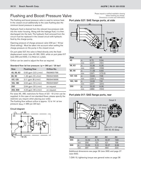
30/36 Bosch Rexroth Corp. <strong>A<strong>A2FM</strong></strong> RA 91 001/07.05Flushing and Boost Pressure ValveThe flushing and boost pressure valve is used to remove heat.In the closed circuit additionally to the case flushing also theminimum boost pressure is assured.Hydraulic fluid is drained from the relevant low-pressure sideinto the motor housing. Along with the leakage fluid, it is thendischarged into the tank. The hydraulic fluid removed from thecircuit must be replaced in the closed circuit with hydraulicfluid by the charge pump.Opening pressure of charge pressure valve 230 psi / 16 bar(fixed setting). Must be taken into account when setting thecharge pressure on the pump in the closed circuit.On port plate 527, the valve is fitted directly onto the fixeddisplacement motor (size 45-180, 250), while on port plate 017(size 355 and 500), it is fitted on a plate.Orifice can be used to adjust the flow as required.Standard flow (at low pressure Δp = 365 psi / 25 bar)Size Flushing flow Orifice-No.45, 56, 63 0.93 gpm (3.5 L/min) R90965176680, 90 1.32 gpm (5 L/min) R909419695107, 125 2.11 gpm (8 L/min) R909419696160, 180 2.64 gpm (10 L/min) R909419697250 2.64 gpm (10 L/min) on request355, 500 4.23 gpm (16 L/min) on requestFor sizes 45...180, restrictors for flows of 3,5 - 10 L/min can besupplied. In the case of non-standard flows, please specify therestrictor you require when placing your order.The flushing flow without orifice is approx. 12 to 14 l at lowpressure Δp ND = 365 psi (25 bar).Circuit diagramT1A (B)Please request a certified installation drawingbefore finalizing your design.Dimensions in inches and (millimeters)Port plate 527: SAE flange ports, at sideA1A2Size A1 A245 in 9.72 5.94mm (247) (151)56, 63 in 10.36 6.26mm (263) (159)80, 90 in 11.69 6.83mm (297) (173.5)107, 125 in 12.84 7.56mm (326.1) (192)160, 180 in 13.66 7.91mm (347) (201)250 in 15.20 6.06mm (386) (154)Port plate 017: SAE flange ports, rearBYM16x2; 0.83 deep 1 )21 deep 1 )XA2A4Detail Y3.86(98)Detail XBAA1.57 (40)A1A3DIA 0.71; 1.57 deepDIA 18; 40 deepT2B (A)Size A1 A2 A3 A4355 in 14.02 4.72 16.57 7.80mm 356 120 421 198500 in 15.63 5.12 18.27 8.66mm 397 130 464 220Additional dimensions see page 26 (size 355) and page 27(size 500).1 ) DIN 13, tightening torque see general notes on page 36
RA 91 001/07.05 <strong>A<strong>A2FM</strong></strong> Bosch Rexroth Corp. 31/36Pressure Relief ValvesThe pressure relief valves MHDB (as to RE 64642) protect themotor from excess pressure. When the set opening pressure isreached the hydraulic fluid flows from the high pressure side tothe low pressure side.The pressure relief valves can only be supplied in conjunctionwith the port plates 181, 191 or 192 (counterbalance valve forfitting on port plate 181, see next page).Setting range opening pressure ___ 725 - 6000 psi (50 - 420 bar)At design "with pressure sequence range" (192) a higherpressure setting can be realized by applying an external pilotpressure of 360 - 435 psi (25 - 30 bar) at port p St .Please indicate in clear text when ordering:– opening pressure of the pressure relief valve– opening pressure at pilot pressure applied at p St(for design 192 only)Design without pressure sequence range "191"T 1 M BBUnit dimensionsD9T 2Detail YD10D12BAD1D2D5D11D13T 1M BPlease request a certified installation drawingbefore finalizing your design.Dimensions in inches and (millimeters)YD3D7D6S 1only for portplate "181"Detail Z:Design without pressuresequence range"191" or "181"D8ZM BS 1 M ADetail Z:Design with pressuresequence range "192"D8D4D6T 2M AS 1Design with pressure sequence range "192"T 1 M B p StT 2M Ap StABS 1AM B S 1PortsA, B Service line ports SAE J518S 1 Boosting (only for port plate 191/192)M A , M B Measuring ports (plugged)p St Pilot pressure port (only for port plate 192)M ASize A, B 1 ) S 2 1 ) M A , M B p 3 St )28, 32 SAE 3/4 in M22x1,5; M20x1,5; G 1/40.55 (14) deep 0.55 (14) deep 2 )45 SAE 3/4 in M22x1,5; M20x1,5; G 1/40.55 (14) deep 0.55 (14) deep 2 )56, 63 SAE 3/4 in M26x1,5; M26x1,5; G 1/40.63 (16) deep 0.63 (16) deep 2 )80, 90 SAE 1 in M26x1,5; M26x1,5; G 1/40.63 (16) deep 0.63 (16) deep 2 )107, 125 SAE 1 / 4 in M26x1,5; M26x1,5; G 1/40.63 (16) deep 0.63 (16) deep 2 )160, 180 SAE 1 / 4 in M26x1,5; M30x1,5; G 1/40.63 (16) deep 0.63 (16) deep1 ) SAE J518 2 ) DIN 3852 3 ) DIN ISO 228Size D1 D2 D3 D4 D5 D6 D7 D8 D9 D10 D11 D12 D13 4 )28, 32 MHDB.16 in 8.98 8.07 0.98 2.48 7.60 4.02 3.43 1.42 2.60 2.00 0.94 0.75 M10; 0.67 deepmm 228 205 25 63 193 102 87 36 66 50.8 23.8 19 17 deep45 MHDB.16 in 9.72 8.78 0.87 2.36 8.35 4.45 3.86 1.42 2.60 2.00 0.94 0.75 M10; 0.67 deepmm 247 223 22 60 212 113 98 36 66 50.8 23.8 19 17 deep56, 63 MHDB.22 in 10.87 9.76 0.75 2.24 9.21 4.88 4.13 1.65 2.95 2.00 0.94 0.75 M10; 0.51 deepmm 276 248 19 57 234 124 105 42 75 50.8 23.8 19 13 deep80, 90 MHDB.22 in 11.81 10.73 0.69 2.17 10.16 5.28 4.49 1.65 2.95 2.25 1.09 0.98 M12; 0.71 deepmm 300 272.5 17.5 55 258 134 114 42 75 57.2 27.8 25 18 deep107, 125 MHDB.32 in 13.11 11.89 0.39 1.89 11.26 5.89 5.12 2.09 3.31 2.63 1.25 1.26 M14; 0.75 deepmm 333 302 10 48 286 149.5 130 53 84 66.7 31.8 32 19 deep160, 180 MHDB.32 in 14.33 13.11 0.20 1.69 12.48 6.69 5.87 2.09 3.31 2.63 1.25 1.26 M14; 0.75 deepmm 364 333 5 43 317 170 149 53 84 66.7 31.8 32 19 deep4 ) DIN 13, tightening torque seegeneral notes on page 36Assembly instructions for port plate with pressure sequence range “192”:When fitting the hydraulic line on the p st port, the lock nut must be held in place!