Axial Piston Fixed Displacment Motor AA2FM (A2FM) - Group VH A/S
Axial Piston Fixed Displacment Motor AA2FM (A2FM) - Group VH A/S
Axial Piston Fixed Displacment Motor AA2FM (A2FM) - Group VH A/S

Create successful ePaper yourself
Turn your PDF publications into a flip-book with our unique Google optimized e-Paper software.
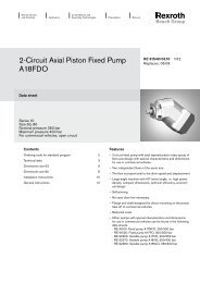
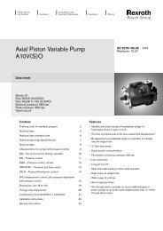
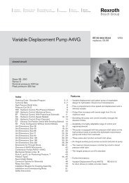
Electric Drivesand ControlsHydraulicsLinear Motion andAssembly TechnologiesPneumaticsService<strong>Axial</strong> <strong>Piston</strong><strong>Fixed</strong> <strong>Displacment</strong> <strong>Motor</strong> <strong>A<strong>A2FM</strong></strong>(<strong>A2FM</strong>)RA 91 001/07.05 1/36Replaces: 11.04Technical data sheetSeries 6Sizes Nominal pressure/Peak pressure5 4600/5100 psi (315/350 bar)10...200 5800/6500 psi (400/450 bar)250...1000 5100/5800 psi (350/400 bar)open and closed circuitsContentsOrdering Code / Standard Program 2...3Technical Data 4...7Ordering Code / Unit Dimensions, Size 5 8Unit Dimensions, Sizes 10, 12, 16 9Unit Dimensions, Sizes 23, 28, 32 10...11Unit Dimensions, Size 45 12...13Unit Dimensions, Sizes 56, 63 14...15Unit Dimensions, Sizes 80, 90 16...17Unit Dimensions, Sizes 107, 125 18...19Unit Dimensions, Sizes 160, 180 20...21Unit Dimensions, Size 200 22Unit Dimensions, Size 250 23Unit Dimensions, Size 355 24Unit Dimensions, Size 500 25Unit Dimensions, Size 710 26Unit Dimensions, Size 1000 27Flushing and Boost Pressure Valve 28Pressure Relief Valve 29Counterbalance Valve BVD 30...31Speed Measurement 32Installation and Commissioning Notes 33General Notes 36Features– <strong>Fixed</strong> displacement motor <strong>A<strong>A2FM</strong></strong> of axial piston, bent axisdesign, suitable for hydrostatic drives in open and closedcircuits– Use in mobile and industrial applications– The output speed depends on the flow capacity of the pumpand the displacement of the motor– The torque increases with the pressure differential betweenthe high and low pressure side and with increasing displacement– Careful selection of the displacements offered, permit sizesto be matched to practically every application– High power density– Compact design– High overall efficiency– Excellent starting torque efficiency– Economical conception– One piece pistons with piston rings
2/36 Bosch Rexroth Corp. <strong>A<strong>A2FM</strong></strong> RA 91 001/07.05Ordering Code / Standard Program (ordering code size 5 see page 10)M / 6 W – V01 02 03 04 05 06 07 08 09 10 11 12 13 14010203Hydraulic fluidMineral oil, HFD for sizes 250...1000 only in combination with long-life bearing “L“ (no code)HFB-, HFC hydraulic fluidSizes 10...200 (no code)Sizes 250...1000 (only in combination with long-life bearing “L“) E-<strong>Axial</strong> piston unit 10...180 200 250 355...1000Bent axis design,Version SAE – – AA2Ffixed displacementVersion ISO – – A2FDrive shaft bearing 10...200 250...500 710...1000Mechanical bearing (no code) –Long-life bearing – LMode of operation04 <strong>Motor</strong> (plug-in motor A2FE see RE 91008) M05SizeSize ≈ displacement V g (cm 3 )Size 10 12 16 23 28 32 45 56 63 80in 3 /rev. 0.63 0.73 0.98 1.40 1.71 1.95 2.78 3.42 3.84 4.91Size 90 107 125 160 180 200 250 355 500 710 1000in 3 /rev. 5.49 6.51 7.63 9.79 10.98 12.20 15.25 21.66 30.51 43.33 61.02Series06 607Indexsizes 10...180 1size 200 3sizes 250...1000 0Direction of rotation08 Viewed on shaft end alternating WSeals09 FKM (flour-caoutchouc) V10Shaft end 10 12 16 23 28 32 45 56 63 80 90 107 125 160 180 250SAE Version SAE– – S(AA2F) Splined shaft– – – – – – – – – – – – – – T– – – – – – – – – – – – U– – – – – – – – – – – – – – QParallel keyed shaft– – – – BDIN 6885– – – – – – – – – – – – – – – PSAE parallel keyed shaft – – – – – – – – – – – – – – – KISO Version(A2F)Splined shaftDIN 5480Parallel keyed shaftDIN 6885200 355 500 710 1000– – – – A– Z– – – – B– P
RA 91 001/07.05 <strong>A<strong>A2FM</strong></strong> Bosch Rexroth Corp. 3/36Ordering Code / Standard Program (ordering code size 5 see page 10)M / 6 W – V01 02 03 04 05 06 07 08 09 10 11 12 13 14Mounting flange 10 12 16 23 28 32 45 56 63 80 90 107 125 160 180 250SAE Version2-bolt – SAE – – – – – – – – – – – – – C(AA2F)4-bolt – SAE – – – – – D11ISO Version(A2F)– – – – – – – – – – – – – – DN200 355 500 710 10004-bolt – ISO – – – – B8-bolt – ISO – HService line portsAA2F 1 ) 10 12 16 23 28 32 45 56 63 80 90 107 125 160 180 250SAE flange ports A and B, rear 51 0 – – – 51012SAE flange ports A and B,at side, opposite sideThreaded ports A and B,at side, opposite sideThreaded ports A and B,at side and rear 2 )SAE flange ports A and B,bottom 2 )Port plate for fitting a counterbalancevalves 3 )Port plate with integrated pressurerelief valve 3 )52 0 – – – 5207 – – – – – – 527530 – – – – – – – – – – 530540 – – – – – – – – – – – – – 540600 – – – – – – – – – – – – – – 600181 – – – – – 18119 1 – – – – – 1912 – – – – – 192A2F 3 ) 200 355 500 710 1000SAE flange ports A and B, rear 01 0 0107 – m m 017SAE flange ports A and B, bottom 10 0 – – – – 100ValvesWithout valve 0With pressure relief valves (without pressure sequence range) 1With pressure relief valves (with pressure sequence range) 2With flushing and boost pressure valve 7Speed measurement 10...16 23...180 200 250 355...1000Without speed measurement (no code)13 Prepared for speed measurement with ID sensor 4 ) – – – – DPrepared for speed measurement with HDD sensor 4 ) – – 5 ) m FSpecial designStandard version (no code)14Specific version for slew drive applications (standard for port plate 19)J1 ) threads of fastening screws and service lines are SAE (UN/UNF)2 ) threaded ports at side are plugged with locking screw3 ) threads of fastening screws are metric4 ) complete order recommended (<strong>A<strong>A2FM</strong></strong> inc. speed sensor)5 ) see RE 91001 (ISO-Version)= available m = in preparation (on request) – = not available
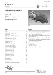
4/36 Bosch Rexroth Corp. <strong>A<strong>A2FM</strong></strong> RA 91 001/07.05Technical DataHydraulic fluidSelection diagramBefore starting project planning, please refer to our datasheets RE 90220 (mineral oil), RE 90221 (environmentallyacceptable hydraulic fluids) and RE 90223 (HF hydraulicfluids) for detailed information regarding the choice of hydraulicfluids and conditions of use.The <strong>A<strong>A2FM</strong></strong> fixed displacement motor is not suitable for usewith HFA. If HFB, HFC and HFD or environmentally acceptablehydraulic fluids are being used, the limitations regardingtechnical data and seals mentioned in RE 90221 andRE 90223 must be observed. When ordering please indicatehydraulic fluid used.viscosity ν SUS (mm2/s)7000500030002000100050030020015010080706050(1600)(1000)(600)(400)(200)(100)(60)(40)(20)(10)(-40°) (-20°)(0°) (20°) (40°) (60°) (80°) (100°)VG 22VG 32VG 68VG 46VG 1007400(1600)170 (36)νopt.80 (16)Viscosity rangeWe recommend that a viscosity (at operating temperature) foroptimum efficiency and service life purposes ofν opt = optimum viscosity 80...170 SUS (16...36 mm 2 /s)selected, taken into consideration the circulation temperature(closed circuit) and tank temperature (open circuits).Limits of viscosity rangeThe following values apply in extreme cases:Sizes 5...200:ν min = 42 SUS (5 mm 2 /s)short term (t < 3 min) at max. permitted temperature oft max = +240°F (+115°C).ν max = 7400 SUS (1600 mm 2 /s),short term (t < 3 min) with cold start (p ≤ 435 psi / 30 bar,n ≤ 1000 rpm, t min = -40°F / -40°C).Sizes 250...1000:ν min = 60 SUS (10 mm 2 /s),short term (t < 3 min) at max. permitted temperature oft max = +195°F (+90°C)ν max = 4600 SUS (1000 mm2/s),short term (t < 3 min) with cold start (p ≤ 435 psi / 30 bar,n ≤ 1000 rpm, t min = -13°F / -25°C).Note that the maximum hydraulic fluid temperature must not beexceeded locally either (e.g. bearing area). The temperature inthe bearing area is - depending on pressure and speed - up to22 °F (12 K) higher than the average case drain temperature.Special measures are necessary at temperatures between-40°F and -13°F (-40°C and -25°C). Please contact us.See RE 90300-03-B for detailed information about operationat low temperatures.40(5)42 (5)(-40°) (-25°) (-10°) (0°) (10°) (30°) (50°) (70°) (90°) (115°)-40° -13° 0° 20° 40° 60° 80° 120° 160° 195° 240°t min = -40°F(-40°C)fluid temperature range t in °F (°C)t max = +240°F(+115°C)Details regarding the choice of hydraulic fluidTo select the correct hydraulic fluid in open circuit applications,the temperature in the tank in relation to the ambient temperaturemust be considered.The hydraulic fluid should be selected so that within theoperating temperature range, the operating viscosity lies withinthe optimum range (ν opt ) (see shaded section of the selectiondiagram). We recommend that the highest possible viscosityrange should be selected in each case.Example: At an ambient temperature of X°F (X°C) an operatingtemperature of 140°F (60°C) is set in the circuit. In theoptimum operating viscosity range (ν opt ; shaded area) thiscorresponds to the viscosity classes VG 46 or VG 68; to beselected: VG 68.Please note: The leakage fluid temperature, which is affectedby pressure and rotational speed, is always higher than the circuittemperature or tank temperature. At no point in the systemmay the temperature be higher than 240°F (115°C) for sizes 5to 200 or 195°F (90°C) for sizes 250 to 1000.If this cannot be achieved due to unusual operating parametersor high ambient temperatures, we recommend to apply bearingflushing at port U (sizes 250 ... 1000) or the use of a flushingand boost pressure valve (see page 30).FiltrationThe finer the filtration, the cleaner the fluid, the longer the servicelife of the axial piston unit.To ensure proper function of the axial piston unit, the Hydraulicfluid must have a cleanliness level of at least20/18/15 according to ISO 4406.At very high hydraulic fluid temperatures (90°C to max. 115°C, notpermitted for sizes 250 to 1000), a cleanliness level of at least19/17/14 according to ISO 4406 is required.Please contact us if these cleanliness leveles cannot be achieved.
RA 91 001/07.05 <strong>A<strong>A2FM</strong></strong> Bosch Rexroth Corp. 5/36Technical DataOperational pressure rangeMaximum pressure on port A or B (pressure data according to DIN 24312)AA2F Sizes 10 12 16 23 28 32 45 56 63 80 90 107 125 160 180 250 Nominal pressure Peak pressureShaft end: S5800 psi (400 bar) 6500 psi (450 bar)S5100 psi (350 bar) 5800 psi (400 bar)Q4350 psi (300 bar) 5100 psi (350 bar)Q4000 psi (280 bar) 4600 psi (315 bar)T5800 psi (400 bar) 6500 psi (450 bar)U5800 psi (400 bar) 6500 psi (450 bar)B5100 psi (350 bar) 5800 psi (400 bar)P5100 psi (350 bar) 5800 psi (400 bar)K5100 psi (350 bar) 5800 psi (400 bar)A2F Sizes 5 200 355 500 710 1000 Nominal pressure Peak pressureShaft end: Z5100 psi (350 bar) 5800 psi (400 bar)A5800 psi (400 bar) 6500 psi (450 bar)P5100 psi (350 bar) 5800 psi (400 bar)B5100 psi (350 bar) 5800 psi (400 bar)B3000 psi (210 bar) 3600 psi (250 bar)C4600 psi (315 bar) 5100 psi (350 bar)With pulsating loads over p N = 4600 psi / 315 bar (p max = 5100 psi / 350 bar);we recommend the use of a splined shaft (<strong>A<strong>A2FM</strong></strong> 10...250: S, T or U / <strong>A2FM</strong> 200: A / <strong>A2FM</strong> 355...1000: Z)The sum of the pressure at ports A and B may not exceed 10000 psi / 700 bar (A2F5: 9000 psi / 630 bar)Attention: shaft end with drives of radial force loads at the drive shaft (pinion, V-belt drives) necessitate reduction of the nominalpressure to p N = 4600 psi (315 bar)! Sizes 250...1000 please contact us.Minimum inlet pressure, see page 8Direction of flowDirection of rotation, viewed on shaft endclockwisecounter-clockwiseA to BB to ASpeed rangeNo limit to minimum speed n min . If uniform motion is required,nmin must not be less than 50 rpm. See table on page 7 formaximum speed.Long-life bearing (sizes 250...1000)For long service life and use with HF hydraulic fluids. Same externaldimensions as the motor with standard long-life bearingcan be supplied. Flushing of bearing and case via the U-port isrecommended.Flow (recommended)Size 250 355 500 710 1000q v flow gpm 2.6 4.2 4.2 4.2 4.2L/min 10 16 16 16 16
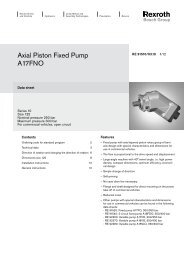
6/36 Bosch Rexroth Corp. <strong>A<strong>A2FM</strong></strong> RA 91 001/07.05Technical DataShaft seal ringPermissible pressure loadThe service life of the shaft seal ring is affected by the speed ofthe motor and the case drain pressure. The permitted loadingwith intermittent case drain pressure depends on the rotationalspeed (see chart). Short-term (t < 5 min) pressure spikes of upto 145 psi (10 bar) absolute are permitted.The average permanent case drain pressure must not exceed43.5 psi (3 bar) absolute.The pressure in the case must be equal to or greater than theexternal pressure on the shaft seal.Sizes 10...200barpsi101409perm. pressure pabs. max. (bar)8sizes 10, 12, 1612076sizes 23, 28, 32 10054size 45sizes 80, 90sizes 56, 638060sizes 107, 125340sizes 160, 1802size 200201150 1000 2000 3000 4000 5000 6000 7000 8000Sizes 250...1000bar6perm. pressure pabs. max. (bar)5432sizes 710, 1000size 500speed n (rpm)size 250size 35510 500 1000 1500 2000 2500speed n (rpm)Temperature rangeThe FKM shaft seal is admissible for a housing temperaturerange from-13°F to +240°F (-25°C to +115°C) at sizes 5...200 and-13°F to +195°F (-25°C to +90°C) at sizes 250...1000Note:For applications below -13°F (-25 °C) a Buna-N (NBR) shaftseal is necessary (admissible temperature range -40 °F to+195 °F / -40 °C to +90 °C). Please contact us.psi8070605040302015
RA 91 001/07.05 <strong>A<strong>A2FM</strong></strong> Bosch Rexroth Corp. 7/36Technical DataTable of values (theoretical values, ignoring η mh and η v ; values rounded)Size 5 10 12 16 23 28 32 45 56 63 80Diplacement V g in 3 0.30 0.63 0.73 0.98 1.40 1.71 1.95 2.78 3.42 3.84 4.91cm 3 4.93 10.3 12 16 22.9 28.1 32 45.6 56.1 63 80.4Speed max. n max rpm 10000 8000 8000 8000 6300 6300 6300 5600 5000 5000 4500n max intermit. 1 )rpm 11000 8800 8800 8800 6900 6900 6900 6200 5500 5500 5000Flow max. q V max gpm 13 21.8 25.3 33.9 38.2 46.6 52.2 67.4 74.0 83.1 95.6L/min 49 82 96 128 144 176 201 255 280 315 360Torque constants T K lb-ft/psi 0.004 0.0084 0.0097 0.013 0.019 0.023 0.026 0.037 0.045 0.051 0.065Nm/bar 0.076 0.164 0.19 0.25 0.36 0.445 0.509 0.725 0.89 1.0 1.27Torque at Δp = 5100 psi T lb-ft 18 2 ) 42 49 66 94 115 132 188 231 259 332Δp = 350 bar T Nm 24,7 2 ) 57 67 88 126 156 178 254 312 350 445Δp = 5800 psiT lb-ft – 48 56 75 107 131 150 213 263 295 377Δp = 400 bar T Nm – 65 76 100 144 178 204 290 356 400 508Mass moment of inertia J lbs-ft 2 0.0019 0.00 95 0.0095 0.0095 0.0285 0.0285 0.0285 0.0569 0.0997 0.0997 0.1708around output shaftkgm 2 0.00008 0.0004 0.0004 0.0004 0.0012 0.0012 0.0012 0.0024 0.0042 0.0042 0.0072Filling capacity gal 0.045 0.045 0.045 0.053 0.053 0.053 0.087 0.119 0.119 0.145L 0.17 0.17 0.17 0.20 0.20 0.20 0.33 0.45 0.45 0.55Mass (approx.) m lbs 5.5 12 12 12 21 21 21 30 40 40 51kg 2.5 5.4 5.4 5.4 9.5 9.5 9.5 13.5 18 18 23Size 90 107 125 160 180 200 250 355 500 710 1000Displacement V g in 3 5.49 6.51 7.63 9.79 10.98 12.20 15.25 21.66 30.51 43.33 61.02cm 3 90 106.7 125 160.4 180 200 250 355 500 710 1000Speed max. n max rpm 4500 4000 4000 3600 3600 2750 2700 2240 2000 1600 1600n 1 max intermit. )rpm 5000 4400 4400 4000 4000 3000 – – – – –Flow max. q V max gpm 106.9 112.7 132.1 152.5 171.1 145.2 178 210 264 300 422L/min 405 427 500 577 648 550 675 795 1000 1136 1600Torque constants T K lb-ft/psi 0.073 0.086 0.101 0.130 0.146 0.162 0.202 0.287 0.405 0.575 0.809Nm/bar 1,43 1,70 1,99 2,54 2,86 3,18 3,98 5,65 7,96 11,3 15,9Torque at Δp = 5100 psi T lb-ft 371 440 516 662 742 825 1030 1465 2063 2930 4127Δp = 350 bar T Nm 501 595 697 889 1001 1114 1393 1978 2785 3955 5570Δp = 5800 psi T lb-ft 422 500 587 753 844 938 – – – – –Δp = 400 bar T Nm 572 680 796 1016 1144 1272 – – – – –Mass moment of inertia J lbs-ft 2 0.1708 0.2753 0.2753 0.5221 0.5221 0.8970 1.4475 2.4205 4.2240 13.052 13.052around output shaftkgm 2 0.0072 0.0116 0.0116 0.0220 0.0220 0.0378 0.061 0.102 0.178 0.55 0.55Filling capacity gal 0.145 0.211 0.211 0.291 0.291 0.713 0.660 0.925 1.110 2.113 2.113L 0.55 0.8 0.8 1.1 1.1 2.7 2.5 3.5 4.2 8 8Mass (approx.) m lbs 51 71 71 99 99 145 161 242 342 715 741kg 23 32 32 45 45 66 73 110 155 325 3361 ) intermittent maximum speed: overspeed at discharge and over-running travel operations, t < 5 sec. and Δp < 2200 psi (150 bar)2 ) Δp = 4600 psi (315 bar)
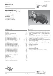
8/36 Bosch Rexroth Corp. <strong>A<strong>A2FM</strong></strong> RA 91 001/07.05Technical DataDetermining the sizeV g • nV g • nFlow q v = gpm q v = L/min231 • η v 1000 • η vq v • 231 • η vq v • 1000 • η vSpeed n = rpm n = rpmV gV g • Δp • η mhV g • Δp • η mhTorque T = lb-ft T = Nm24 • π 20 • π2 π • T • n q v • Δp • η t 2 π • T • n q v • Δp • η tPower P = = HP P = = kW33 000 1714 60 000 600V g = Diplacement per revolution in in 3 (cm 3 )Δp = Differential pressure in psi (bar)n = Speed in rpmη v = Volumetric efficiencyη mh = Mechanical-hydraulic efficiencyη t = Overall efficiency((((V g))))Minimum inlet pressure on service line port A (B)In order to avoid damage of the motor a minimum inlet pressureat the inlet zone must be assured. The minimum inlet pressureis related to the rotational speed of the fixed motor.inlet pressure pabs. min in barbar12108642100.20.40.6psi160140120100806040200.8 1.0speed n/n maxPlease contact us if these conditions cannot be satisfied
RA 91 001/07.05 <strong>A<strong>A2FM</strong></strong> Bosch Rexroth Corp. 9/36Technical DataPermissible radial and axial loading on the drive shaftThe values given are maximum values and do not apply to continous operation.Size 5 10 12 16 23 28 32 45 56 63 80Radial force, max. 1 )at distance a(from shaft collar)<strong>Axial</strong> force, max. 3 )–Fax+FqPermissible axial force/psi (bar)operating pressureaF q max lbf 160 472 562 730 865 1079 1214 1630 1832 2057 2304 2 )N 710 2100 2500 3250 3850 4800 5400 7250 8150 9150 10250a in 0.47 0.63 0.63 0.63 0.63 0.63 0.63 0.71 0.71 0.71 0.79mm 12 16 16 16 16 16 16 18 18 18 20+F ax max lbf 40 72 72 72 112 112 112 142 180 180 225N 180 320 320 320 500 500 500 630 800 800 1000–F ax max lbf 40 72 72 72 112 112 112 142 180 180 225±F ax per. /psi(bar)N 180 320 320 320 500 500 500 630 800 800 1000lbf/psi 0.023 0.05 0.05 0.05 0.08 0.08 0.08 0.11 0.13 0.13 0.16N/bar 1.5 3.0 3.0 3.0 5.2 5.2 5.2 7.0 8.7 8.7 10.6Size 90 107 125 160 180 200 250 355 500 710 1000Radial force, max. 1 )F q max lbf 2574 2 ) 2720 3170 3664 4114 5148 270 337 427 674 584at distance aN 11450 12100 14100 16300 18300 22900 1200 4 ) 1500 4 ) 1900 4 ) 3000 4 ) 2600 4 )(from shaft collar) Fqa in 0.79 0.79 0.79 0.98 0.98 0.98 1.61 2.07 2.07 2.66 2.66amm 20 20 20 25 25 25 41 52.5 52.5 67.5 67.5<strong>Axial</strong> force, max. 3 ) +F ax max lbf 225 281 281 360 360 360 450 562 674 989 989–Fax+Permissible axial force/psi (bar)operating pressureN 1000 1250 1250 1600 1600 1600 2000 2500 3000 4400 4400–F ax max lbf 225 281 281 360 360 360 450 562 674 989 989±F ax per. /psi(bar)N 1000 1250 1250 1600 1600 1600 2000 2500 3000 4400 4400lbf/psi 0.16 0.20 0.20 0.26 0.26 0.26 5 ) 5 ) 5 ) 5 ) 5 )N/bar 10.6 12.9 12.9 16.7 16.7 16.71 ) during intermittent operation (sizes 5...200)2 ) value for Q-shaft: F q max = 2023 lbf (9000 N)3 ) max. permissible axial force when stopped or when axial piston unit working in pressureless conditions.4 ) when stopped or when axial piston unit working in pressureless conditions. Higher forces are permitted when under pressure,please contact us.5 ) please contact usWhen considering the permissible axial force, the force-transfer direction must be taken into account.– F ax max = increase in sevice life of bearings+ F ax max = reduction in service life of bearings (avoid if at all possible)Gear driveEffect of radial force F q on the service life of the bearingsBy selecting a suitable force-transfer direction of F q , the stressDirection <strong>Motor</strong> of rotation beiwechselnderon the bearing caused by the internal transmission forces canalternating Drehrichtungbe reduced, thus achieving the optimum service life for thebearing. Recommended position of mating gear depending ondirection of rotation. Examples:ϕ optϕ optϕ optV-belt driveϕ optGear driveV-belt driveSize ϕ opt. ϕ opt.10-180 ± 70° ± 45°200-1000 ± 45° ± 70°A B A B<strong>Motor</strong> LinkslaufDruck amAnschluß BCounter-clockwisedirection of rotation<strong>Motor</strong> RechtslaufDruck amAnschluß AClockwisedirection of rotationPressure on port B Pressure on port A<strong>Motor</strong> LinkslaufCounter-clockwiseDruck amdirectionAnschlußof rotationBPressure on port B
10/36 Bosch Rexroth Corp. <strong>A<strong>A2FM</strong></strong> RA 91 001/07.05Ordering Code / Standard Program – Size 5A2F 5 / 60 W – 301 02 03 04 05 06<strong>Axial</strong> piston unit01 Bent axis design, fixed displacement A2FSizeSize 502 ≈ Displacement V g in 3 /rev. 0.30cm 3 /rev. 4.93Series03 60Direction of rotation04 Viewed on shaft end alternating WShaft end05Parallel keyed shaft DIN 6885 BTapered shaft with threaded end and woodruff key per DIN 6888 CAdditional instructions in text formSealsThe fixed motor A2F5 is equipped withBuna-N (NBR) seals in standard design.In case of need FKM- (fluor-caoutchouc)seals please indicate when ordering inclear text:"with FKM-seals"Service line ports06 Threaded ports A und B at side, metric 3Unit Dimensions, Size 5 – ISO DesignShaft ends2.05 (52)0.32(8)DIA 2.362DIA 2.360(DIA 60 –0.046 )0.16(4)2.00 (51)2.93 (74.5)2.30 (58.5)0.69(17.5)25°YR 0.24(R 6)DIA 1.91(DIA 48.5)2.76DIA 2.96DIA 2.95(DIA 75 ±0,1)(70)Please request a certified installation drawingbefore finalizing your design.Dimensions in inches and (millimeters)T 2ATT 1 13.15 (80)BPorts2.76(70)0.25(6.4)Detail Y2.44(62)B0.53(13.5)Parallel keyed shaftDIN 6885 – A4x4x20 (mm)p N = 3000 psi (210 bar)DIA 0.473DIA 0.472+0.012(DIA 12 +0.001)M4x0.7 1 ) 3 )0.13(3.2)0.39(10)R 0.02(R 0.4)0.95(24)DIA 0.59(DIA 15)C Tapered shaft with threaded end andwoodruff key (3x5 mm) DIN 6888(taper 1:10) p N = 4600 psi (315 bar)DIA 0.50(DIA 12.8)M10x1 2 ) 3 )0.16(4)1.30 (33)0.87(22)0.29(7.3)DIA 0.59(DIA 15)A, B Service line portsDIN 3852T 1 , T 2Case drain portsDIN 3852M18x1,5;0.47 (12) deepM10x1;0.31 (8) deep1) centering bore according to DIN 332(thread according to DIN 13)2) thread according to DIN 3852,max. tightening torque: 20 lb-ft (30 Nm)100 lb-ft 3 )(140 Nm)20 lb-ft 3 )(30 Nm)3 ) please observe the general notes for the max.tightening torques on page 36
RA 91 001/07.05 <strong>A<strong>A2FM</strong></strong> Bosch Rexroth Corp. 11/36Unit Dimensions, Sizes 10, 12, 16 – SAE DesignPort plate 53: Threaded ports, at sidePlease request a certified installation drawingbefore finalizing your design.Dimensions in inches and (millimeters)4.25 (108)0.31 (7.9)0.47 (12)6.85 (174)5.75 (146)T1DIA 4.000DIA 3.999(DIA 101.6 -0.05 )0.38(9.7)40°Flange SAE J7442.13(54)2.83 (72)T25.63 (143)7.01 (178)1 .14(29)2.20 (56)(92)3.62DIA 3.35(DIA 85)Y0.55(14)BDetail YA(121)4.763.35(85)Shaft endsS Splined shaft 7/8 in 13T 16/32 DP 1 )(SAE J744 – 22-4 (B))p N = 5800 psi (400 bar)B Parallel keyed shaftDIN 6885 – AS8x7x32 (mm)p N = 5100 psi (350 bar)5/16-18UNC-2B 2 ) 4 )0.750.24 (19)(6)0.31(8)1.32(33.5)DIA 1.10(DIA 28)0.31500.3135(8 h9 )(7)0.27DIA 0.9848DIA 0.9843+0.015(DIA 25 +0.002 )1.10(28)M10x1.5 3 ) 4 )0.87 (22)0.30 (7.5)1.57(40)DIA 1.10(DIA 28)E1x0.2DIN 509PortsA, B Service line ports ISO 11926 1 1/16 in -12 UN-2B; 0.79 (20) deep 265 lb-ft (360 Nm) 4 )T 1 , T 2 Case drain ports (T 2 plugged) ISO 11926 9/16 in -18 UNF-2B; 0.51 (13) deep 60 lb-ft (80 Nm) 4 )1 ) 30° pressure angle, flat root side fit, tolerance class 52 ) thread according to ISO 683 ) centering bore according to DIN 332 (thread according to DIN 13)4 ) please observe the general notes for the max. tightening torques on page 36
12/36 Bosch Rexroth Corp. <strong>A<strong>A2FM</strong></strong> RA 91 001/07.05Unit Dimensions, Sizes 23, 28, 32 – SAE DesignPlease request a certified installation drawingbefore finalizing your design.Dimensions in inches and (millimeters)0.31 (7.9)4.92 (125)0.79 (20)45°5.75(146)45°DIA 5.000DIA 4.998(DIA 127 -0.05 )0.50(12.7)Flange SAE J7442.28(58)2.32(59)T1T 240°1.06(27)DIA 4.17(DIA 106)14.30.56DIA 6.38(DIA 162)(146)5.75Shaft endsS Splined shaft 1 1/4 in 14T 12/24 DP 1 )(SAE J744 – 32-4 (C))p N = 5800 psi (400 bar)B Parallel keyed shaftDIN 6885 – AS8x7x40 (mm)p N = 5100 psi (350 bar)7/16-14 UNC-2B 2 ) 4 )1.10 (28)0.37 (9.5)0.31 (8)1.89 (48)DIA 1.38(DIA 35)0.31500.3135(8 h9 )0.27 (7)(33)1.30DIA 1.182DIA 1.181(DIA 30 +0.015+0.002 )M10x1.5 3 ) 4 )0.871.97(50)(22)0.30 (7.5)E1x0.2DIN 509DIA 1.38(DIA 35)PortsA, B Service line ports (see port plates)T 1 , T 2 Case drain ports (T 2 plugged) ISO 11926 3/4 in -16 UNF-2B; 0.59 (15) deep 120 lb-ft (160 Nm) 4 )1 ) 30° pressure angle, flat root side fit, tolerance class 52) thread according to ISO 683 ) centering bore according to DIN 332 (thread according to DIN 13)4 ) please observe the general notes for the max. tightening torques on page 36
RA 91 001/07.05 <strong>A<strong>A2FM</strong></strong> Bosch Rexroth Corp. 13/36Unit Dimensions, Sizes 23, 28, 32 – SAE DesignPort platesPlease request a certified installation drawingbefore finalizing your design.Dimensions in inches and (millimeters)51 SAE flange ports, rear 52 SAE flange ports, at sideDetail Y2.32 (59)0.51 (13)0.72 (18.2)Detail Y(78)(104)3.074.090.72(18.2)1.59(40.5)2.76 (70)4.61 (117)BA6.69 (170)7.44 (189)YBA1.59 (40.5)4.53 (115)6.34 (161)8.15 (207)BY4.72(120)A, B Service line ports(high pressure series)SAE J518 1/2 in A, B Service line ports(high pressure series)Fastening threads ISO 68 5/16 in-18 UNC-2B;0.71 (18) deep 1 )SAE J518 1/2 inFastening threads ISO 68 5/16 in-18 UNC-2B;0.71 (18) deep 1 )53 Threaded ports, at side 54 Threaded ports, at side and rearDetail YDetail Y2.76 (70)4.61 (117)BA3.50 (89)4.65 (118)BA6.34 (161)8.15 (207)A, B Service line portsISO 11926Y1 5/16 in -12 UN-2B;0.79 (20) deep4.72(120)400 lb-ft 1 )(540 Nm)1 ) please observe the general notes for the max. tightening torques on page 367.24 (184)8.23 (209)A, B Service line portsISO 11926Y1 5/16 in -12 UN-2B;0.79 (20) deeponce plugged each2.28 (58)4.92 (125)400 lb-ft 1 )(540 Nm)Note: port plates 18 and 19 see pages 31, 32
14/36 Bosch Rexroth Corp. <strong>A<strong>A2FM</strong></strong> RA 91 001/07.05Unit Dimensions, Size 45 – SAE DesignPlease request a certified installation drawingbefore finalizing your design.Dimensions in inches and (millimeters)5.24(133)0.51 (13)0.79 (20)45°45°0.31 (7.9)5.75(146)T 1DIA 5.000DIA 4.999(DIA 127 -0.025 )2.56(65)40°1 .18(30)0.56(14.3)DIA 6.38(DIA 162)5.75(146)2.60(66)Flange SAE J744T 2DIA 4.65(DIA 118)Shaft endsS Splined shaft 1 1/4 in 14T 12/24 DP 1 )(SAE J744 – 32-4 (C))p N = 5800 psi (400 bar)P Parallel keyed shaftDIN 6885 – AS8x7x50 (mm)p N = 5100 psi (350 bar)7/16-14 UNC-2B 2 ) 4 )1.10 (28)0.37 (9.5)0.31 (8)1.89 (48)DIA 1.38(DIA 35)0.31500.3135(8 h9 )(7)0.27DIA 1.182DIA 1.181(DIA 30 +0.015+0.002 )1.30 (33)M12x1.75 3 ) 4 )1.100.37 (9.5)2.36(60)(28)E1x0.2DIN 509DIA 1.38(DIA 35)PortsA, B Service line ports (see port plates)T 1 , T 2 Case drain ports (T 2 plugged) ISO 11926 3/4 in -16 UNF-2B; 0.59 (15) deep 120 lb-ft (160 Nm) 4 )1 ) 30° pressure angle, flat root side fit, tolerance class 52 ) thread according to ISO 683 ) centering bore according to DIN 332 (thread according to DIN 13)4 ) please observe the general notes for the max. tightening torques on page 36
RA 91 001/07.05 <strong>A<strong>A2FM</strong></strong> Bosch Rexroth Corp. 15/36Unit Dimensions, Size 45 – SAE DesignPort platesPlease request a certified installation drawingbefore finalizing your design.Dimensions in inches and (millimeters)51 SAE flange ports, rear 52 SAE flange ports, at sideDetail Y7.48 (190)8.58 (218)3.50 (89)4.80 (122)Y0.94 (23.8)2.00(50.8)0.75(19)B2.95 (75)5.79(147)A2.00(50.8)7.05 (179)9.09 (231)0.94 (23.8)B3.15 (80)(133)5.24YBDetail Y5.04(128)AA, B Service line ports(high pressure series)SAE J518 3/4 in A, B Service line ports(high pressure series)Fastening threads ISO 68 3/8 in -16 UNC-2B;0.82 (21) deep 1 )1 ) please observe the general notes for the max. tightening torques on page 36SAE J518 3/4 inFastening threads ISO 68 3/8 in -16 UNC-2B;0.82 (21) deep 1 )Note: port plates 18 and 19 see pages 31, 32
16/36 Bosch Rexroth Corp. <strong>A<strong>A2FM</strong></strong> RA 91 001/07.05Unit Dimensions, Sizes 56, 63 – SAE DesignPlease request a certified installation drawingbefore finalizing your design.Dimensions in inches and (millimeters)5.63(143)45°45°0.50 (12.7)0.31 (7.9)0.79 (20)5.75(146)T 1DIA 5.000DIA 4.998(DIA 127 -0.05 )2.83(72)40°1.30(33)0.56(14.3)DIA 6.38(DIA 182)5.75(146)Flange SAE J7442.91(74)T 2DIA 5.04(DIA 128)Shaft endsS Splined shaft 1 1/4 in 14T 12/24 DP 1 )(SAE J744 – 32-4 (C))p N = 5100 psi (350 bar)T Splined shaft 1 3/8 in 21T 16/32 DP 1 )p N = 5800 psi (400 bar)B Parallel keyed shaftDIN 6885 – AS10x8x50 (mm)p N = 5100 psi (350 bar)7/16-14 UNC-2B 2 ) 4 )1.10 (28)0.37 (9.5)0.31(8)1.89 (48)DIA 1.57(DIA 40)7/16-14 UNC-2B 2 ) 4 )1.10(28)0.37 (9.5)0.31 (8)1.89 (48)DIA 1.57(DIA 40)0.39370.3923(10 h9 )0.31(8)DIA 1.379DIA 1.378+0.018(DIA 35 +0.002 )1.50 (38)M12x1.75 3 ) 4 )1.10(28)0.37 (9.5)2.36(60)E1x0.2DIN 509DIA 1.57(DIA 40)PortsA, B Service line ports (see port plates)T 1 , T 2 Case drain ports (T 2 plugged) ISO 11926 3/4 in -16 UNF-2B; 0.59 (15) deep 120 lb-ft (160 Nm) 4 )1 ) 30° pressure angle, flat root side fit, tolerance class 52) thread according to ISO 683 ) centering bore according to DIN 332 (thread according to DIN 13)4 ) please observe the general notes for the max. tightening torques on page 36
RA 91 001/07.05 <strong>A<strong>A2FM</strong></strong> Bosch Rexroth Corp. 17/36Unit Dimensions, Sizes 56, 63 – SAE DesignPort platesPlease request a certified installation drawingbefore finalizing your design.Dimensions in inches and (millimeters)51 SAE flange ports, rear 52 SAE flange ports, at sideDetail Y1.09 (27.8)3.78 (96)5.12 (130)(23.8)0.94B5.79 (147)0.75 (19)A2.25(57.2)3.58 (91)5.91 (150)BDetail YA8.11 (206)9.06 (230)A, B Service line ports(high pressure series)2.00(50.8)2.95(75)SAE J518 3/4 in A, B Service line ports(high pressure series)Fastening threads ISO 68 3/8 in -16 UNC-2B;0.82 (21) deep 1 )Y7.871 ) please observe the general notes for the max. tightening torques on page 3610.16(200)(258)BSAE J518 1 in5.91(150)Fastening threads ISO 68 7/16 in -14 UNC-2B;0.87 (22) deep 1 )YNote: port plates 18 and 19 see pages 31, 32
18/36 Bosch Rexroth Corp. <strong>A<strong>A2FM</strong></strong> RA 91 001/07.05Unit Dimensions, Sizes 80, 90 – SAE DesignPlease request a certified installation drawingbefore finalizing your design.Dimensions in inches and (millimeters)0.50 (12.7)0.31 (8)6.34 (161)0.79 (20)T 145°5.75(146)45°DIA 5.000DIA 4.998(DIA 127 -0.05 )3.27(83)40°1.61(41)0.56 (14.3)DIA 6.38(DIA 162)5.75(146)Flange SAE J7443.66(93)T 2DIA 5.43(DIA 138)Shaft endsU Splined shaft 1 3/8 in 21T 16/32 DP 1 )p N = 5800 psi (400 bar)7/16-14 UNC-2B 2 ) 3 )1.100.37 (9.5)0.31 (8)(28)1.89 (48)DIA 1.77(DIA 45)Q Splined shaft 1 1/4 in 14T 12/24 DP 1 )(SAE J744 – 32-4 (C))Size 80: p N = 4350 psi (300 bar)Size 90: p N = 4000 psi (280 bar)7/16-14 UNC-2B 2 ) 3 )1.100.31 (8)1.890.37 (9.5)(48)(28)DIA 1.77(DIA 45)PortsA, B Service line ports (see port plates)T 1 , T 2 Case drain ports (T 2 plugged) ISO 11926 7/8 in -14 UNF-2B; 0.67 (17) deep 180 lb-ft (240 Nm) 3 )1 ) 30° pressure angle, flat root side fit, tolerance class 52) thread according to ISO 683 ) please observe the general notes for the max. tightening torques on page 36
RA 91 001/07.05 <strong>A<strong>A2FM</strong></strong> Bosch Rexroth Corp. 19/36Unit Dimensions, Sizes 80, 90 – SAE DesignPort platesPlease request a certified installation drawingbefore finalizing your design.Dimensions in inches and (millimeters)51 SAE flange ports, rear 52 SAE flange ports, at side4.09(104)5.67 (144)Detail Y0.98(25)B2.25(57.2)A2.25(57.2)1.09 (27.8)(99)3.90(162)6.38BDetail YA9.13 (232)10.31 (262)Y3.31(84)6.54 (166)1.09(27.8)8.86 (225)11.26 (286)BY6.30(160)A, B Service line ports(high pressure series)SAE J518 1 in A, B Service line ports(high pressure series)Fastening threads ISO 68 7/16 in -14 UNC-2B;0.75 (19) deep 1 )1 ) please observe the general notes for the max. tightening torques on page 36SAE J518 1 inFastening threads DIN 13 7/16 in -14 UNC-2B;0.75 (19) deep 1 )Note: port plates 18 and 19 see pages 31, 32
22/36 Bosch Rexroth Corp. <strong>A<strong>A2FM</strong></strong> RA 91 001/07.05Unit Dimensions, Sizes 160, 180 – SAE DesignPlease request a certified installation drawingbefore finalizing your design.Dimensions in inches and (millimeters)0.50 (12.7)0.31 (7.9)7.480.98 (25)(190)45°7.87(200)45°T 1DIA 6.000DIA 5.998(DIA 152.4 -0.05 )3.78(96)40°1.85(47)0.83(21)DIA 9.00(DIA 228.6)7.87(200)Flange SAE J7444.09(104)T 2DIA 7.09(DIA 180)Shaft endsS Splined shaft 1 3/4 in 13T 8/16 DP 1 )(SAE J744 – 44-4 (D))p N = 5800 psi (400 bar)B Parallel keyed shaftDIN 6885 – AS14x9x70 (mm)p N = 5100 psi (350 bar)5/8-11UNC-2B 2 ) 4 )1.42 (36)0.47 (12)0.47(12)2.64 (67)DIA 2.36(DIA 60)0.55120.5495(14 h9 )0.35 (9)DIA 1.969DIA 1.968+0.018(DIA 50 +0.002 )2.11(53.5)M16x2 3 ) 4 )1.42 (36)0.47 (12)3.54(R1.6)(90)R0.06DIA 2.36(DIA 60)PortsA, B Service line ports (see port plates)T 1 , T 2 Case drain ports (T 2 plugged) ISO 11926 7/8 in -14 UNF-2B; 0.67 (17) deep 180 lb-ft (240 Nm) 4 )1 ) 30° pressure angle, flat root side fit, tolerance class 52) thread according to ISO 683 ) centering bore according to DIN 332 (thread according to DIN 13)4 ) please observe the general notes for the max. tightening torques on page 36
RA 91 001/07.05 <strong>A<strong>A2FM</strong></strong> Bosch Rexroth Corp. 23/36Unit Dimensions, Sizes 160, 180 – SAE DesignPort platesPlease request a certified installation drawingbefore finalizing your design.Dimensions in inches and (millimeters)51 SAE flange ports, rear 52 SAE flange ports, at sideDetail Y1.25Detail Y5.28 (134)7.36 (187)1.26(32)B2.63(66.7)A2.63(66.7)(31.8)4.76 (121)7.36 (187)BA11 .18 (284)12.83 (326)Y3.90(99)7.64 (194)1.25 (31.8)10.59 (269)12.83 (326)BY7.95(202)A, B Service line ports(high pressure series)SAE J518 1 1/4 in A, B Service line ports(high pressure series)Fastening threads ISO 68 1/2 in -13 UNC-2B;0.75 (19) deep 1 )1 ) please observe the general notes for the max. tightening torques on page 36SAE J518 1 1/4 inFastening threads ISO 68 1/2 in -13 UNC-2B;0.75 (19) deep 1 )Note: port plates 18 and 19 see pages 31, 32
24/36 Bosch Rexroth Corp. <strong>A<strong>A2FM</strong></strong> RA 91 001/07.05Unit Dimensions, Size 200 – ISO DesignPort plate 01: SAE flange ports, rearPlease request a certified installation drawingbefore finalizing your design.Dimensions in inches and (millimeters)°6.14 (156)1.58 4.09 (104)0.35(40)1.26(9) (32)T 1459.29(236)45°DIA 7.874DIA 7.872(DIA 200–0.029)1.26(32)25°4.04(102.5)3.50(89)Flange ISO 3019-2T 211.81 (284)12.05 (306)3.03(77)3.31(84)Y6.54(166)0.87(22)ADetail YB9.84(250)8.11 (206)2.63 2.63(66.7) (66.7)A(236)9.29B8.31(211)1.25(31.8)1.26(32)3.90(99)Shaft endsA Splined shaft DIN 5480W50x2x30x24x9gp N = 5800 psi (400 bar)B Parallel keyed shaftDIN 6885 – AS14x9x80 (mm)p N = 5100 psi (350 bar)M16 1 ) 2 )1.42 (36)0.47 (12)0.43 (11)2.17 (55)DIA 2.76(DIA 70)0.55120.5495(14 h9 )0.35 (9)DIA 1.969DIA 1.968(DIA 50 +0.018+0.002 )2.11(53.5)M16x2 1 ) 2 )1.42 (36)0.47(12)3.94R0.06(R1.6)(100)DIA 2.76(DIA 70)PortsA, B Service line ports (high pressure series) SAE J518 1 1/4 inFastening threads DIN 13 M14x2; 0.75 (19) deep 2 )T 1 , T 2 Case drain ports (T 1 plugged) DIN 3852 M22x1.5; 0.55 (14) deep 155 lb-ft (210 Nm) 2 )1 ) centering bore according to DIN 332 (thread according to DIN 13)2 ) please observe the general notes for the max. tightening torques on page 36
RA 91 001/07.05 <strong>A<strong>A2FM</strong></strong> Bosch Rexroth Corp. 25/36Unit Dimensions, Size 250 – SAE DesignPort plate 51: SAE flange ports, rear4.88 (124)0.63(16) 2.520.31 (7.9) (64)U T 14x90°(=360°)45°Please request a certified installation drawingbefore finalizing your design.Dimensions in inches and (millimeters)DIA 6.500DIA 6.498(DIA 165.1 -0.05 )DIA 5.51(DIA 140)26.5°4.13 (105) 4.13 (105)3.66 (93)(172)0.98(25)T 24.88 (124)12.99 (330)13.94 (354)6.770.81 (20.6)DIA12.50(DIA317.5)10.31(262)FlangeSAE J744Y10.31(262)Port plate 52:SAE flange ports, at side1.25 (31.8)Detail Y(32)1.26Detail YBA1.25 (31.8)(210)2.63(66.7)1.26(30)12.17 (309)14.33 (364)B3.23 (82)6.77 (172)BY9.29(236)A1.97 1.97(50) (50)2.63(66.7)8.27Shaft endsS Splined shaft 2 in 15T 8/16 DP 1 )(SAE J744 – 50-4 (F))p N = 5100 psi (350 bar)DIA 1.970DIA 1.964(DIA 50.8 -0.74-0.89 )5/8-11UNC-2B 2 ) 3 )1.42 (36)0.47(12)0.59 (15)2.63 (66.7)DIA 2.36(DIA 60)K Parallel keyed shaft0.5x0.5x3.0 (in) 12.7x12.7x76.7 (mm)p N = 5100 psi (350 bar)0.50100.5000(12.7 +0.025 )(12.7)0.52.22 (56.3)DIA 2.000DIA 1.998(DIA 50.8 -0.03 )5/8-11UNC-2B 2 ) 3 )1.42 (36)0.47 (12)R0.06(R1.6)3.13 (79.4)DIA 2.36(DIA 60)PortsA, B Service line ports (high pressure series) SAE J518 1 1/4 inFastening threads ISO 68 1/2 in -13 UNC-2B; 0.75 (19) deep 3 )T 1 , T 2 Case drain ports (T 2 plugged) ISO 11926 7/8 in -14 UNF-2B; 0.67 (17) deep 180 lb-ft (240 Nm) 3 )U Port for bearing flushing (plugged) ISO 11926 9/16 in -18 UNF-2B; 0.51 (13) deep 60 lb-ft (80 Nm) 3 )1 ) 30° pressure angle, flat root side fit, tolerance class 52 ) thread according to ISO 683) please observe the general notes for the max. tightening torques on page 36
7.80(198)5.04(128)4.02(102)–0.0815.04(128)26/36 Bosch Rexroth Corp. <strong>A<strong>A2FM</strong></strong> RA 91 001/07.05Unit Dimensions, Size 355 – ISO DesignPort plate 01: SAE flange ports, rear1.97 (50)3.27 (83)0.55 (14) 0.93 (23.5)UT1MA (MB)45°13.1922°30’Please request a certified installation drawingbefore finalizing your design.Dimensions in inches and (millimeters)(335)(170)DIA 11.024DIA 11.020(DIA 280 )26 °30’0.71(18)DIA 14.17(DIA 360)DIA 12.60(DIA 320)13.19(335)6.7FlangeISO 3019-21.89(48)Port plate 10:SAE flange ports, bottom14.59 (370.5)12.72 (323)1.10 (28) T23.2 7(83) 12.60 (320)13.78 (350)Detail Y1.25(31.8)BYDetail Y1.44 1.44(36.6) (36.6)BAMBMA3.13(79.4)9.65 (245)Y5.83 (148)7.84 (199)9.49 (241)4.72 (120)M BM A2.63(66.7)1.26(32)A1.58(40)2.36 2.36(60) (60)9.84 (250)1.58(40)Shaft endsZ Splined shaft DIN 5480W60x2x30x28x9gp N = 5100 psi (350 bar)M20x2.5 1 ) 2 )1.65 (42)0.59 (15)0.43 (11)3.23 (82)DIA 2.76(DIA 70)PParallel keyed shaftDIN 6885 – AS18x11x100 (mm)p N = 5100 psi (350 bar)0.70870.7070(18 h9 )0.43 (11)2.52 (64)DIA 2.363DIA 2.362(DIA 60 +0.030+0.011 M20x2.5 1 ) 2 ))1.65 (42)0.59 (15)R0.06(R1.6)4.13 (105)DIA 2.76(DIA 70)PortsPort plate 01: Port plate 10:A, B Service line ports (high pressure series) SAE J518 1 1/2 in 1 1/4 inFastening threads DIN 13 M16x2;0.83 (21) deep 2 ) M14x2; 0.87 (22) deep 2 )T 1 , T 2 Case drain ports (T 2 plugged) DIN 3852 M33x2; 0.71 (18) deep 400 lb-ft (540 Nm) 2 )U Port for bearing flushing (plugged) DIN 3852 M14x1.5; 0.47 (12) deep 60 lb-ft (80 Nm) 2 )M A , M B Measuring ports operating pressure (plugged) DIN 3852 M14x1.5; 0.47 (12) deep 60 lb-ft (80 Nm) 2 )1 ) centering bore according to DIN 332 (thread according to DIN 13)2 ) please observe the general notes for the max. tightening torques on page 36
–0.081RA 91 001/07.05 <strong>A<strong>A2FM</strong></strong> Bosch Rexroth Corp. 27/36Unit Dimensions, Size 500 – ISO DesignPort plate 01: SAE flange ports, rearDIA 12.402DIA 12.398DIA 315 )1.97 (50) 3.86 (98)0.55 (14) 1.08 (27.5)UT1MA (MB)5.59(142)5.59(142)26°30’4.43(112.5)45°0.87(22)22°30’DIA 15.75(DIA 400)Please request a certified installation drawingbefore finalizing your design.Dimensions in inches and (millimeters)14.76 (375)DIA 14.17(DIA 360)(192)(375)7.5614.761.89(48)Flange ISO 3019-2T 21.18 (30)4.37(111) 14.23 (361.5)15.59 (396)8.66(220)YDetail Y1.44 1.44(36.6) (36.6)BAMBMA3.13(79,4)10.63 (270)1.581.58(40) 2.56 2.56 (40)(65) (65)10.87 (276)Shaft endsZ Splined shaft DIN 5480W70x3x30x22x9gp N = 5100 psi (350 bar)M20x2.5 1 ) 2 )1.65 (42)0.59 (15)0.51 (13)3.15 (80)DIA 3.15(DIA 80)PParallel keyed shaftDIN 6885 – AS20x12x100 (mm)p N = 5100 psi (350 bar)0.78740.7854(20 h9 )0.47(12)(74.5)2.93DIA 2.7570DIA 2.7563+0.030(DIA 70 +0.011 )M20x2.5 1 ) 2 )1.65(42)0.59 (15)R0.06(R1.6)4.13 (105)DIA 3.15(DIA 80)PortsA, B Service line ports (high pressure series) SAE J518 1 1/2 inFastening threads DIN 13 M16x2; 0.83 (21) deep 2 )T 1 , T 2 Case drain ports (T 2 plugged) DIN 3852 M33x2; 0.71 (18) deep 400 lb-ft (540 Nm) 2 )U Port for bearing flushing (plugged) DIN 3852 M18x1.5; 0.47 (12) deep 100 lb-ft (140 Nm) 2 )M A , M B Measuring ports operating pressure (plugged) DIN 3852 M14x1.5; 0.47 (12) deep 60 lb-ft (80 Nm) 2 )1) centering bore according to DIN 332 (thread according to DIN 13)2) please observe the general notes for the max. tightening torques on page 36
–0.08928/36 Bosch Rexroth Corp. <strong>A<strong>A2FM</strong></strong> RA 91 001/07.05Unit Dimensions, Size 710 – ISO DesignPort plate 01: SAE flange ports, rearDIA 15.748DIA 15.745(DIA 400 )Please request a certified installation drawingbefore finalizing your design.Dimensions in inches and (millimeters)1.97 (50) 5.16 (131)0.55 (14) 1.63 (41.5)18.31 (465)UT1MA (MB)YT 21.85 1.38 (35)(47) 6.14Detail Y(156) 19.13 (486)1.75 1.7519.96 (507)(44.5)(44.5)Flange ISO 3019-2BA MAMB7.21 7.21(183) (183)18°30’4.02(102)9.92(252)45°0.87(22)22°30’DIA 19.69(DIA 500)DIA 17.72(DIA 450)3.8118.31(236)(465)9.29(96.8)(340)13.391.97(50)3.35 3.35(85) (85)13.54 (344)1.97(50)Shaft endsZ Splined shaft DIN 5480W90x3x30x28x9gp N = 5100 psi (350 bar)M24x3 1 ) 2 )1.97 (50)0.71(18)0.55 (14)4.13 (105)DIA 3.94(DIA 100)PParallel keyed shaftDIN 6885 – AS25x14x125 (mm)p N = 5100 psi (350 bar)0.98430.9822(25 h9 )0.55 (14)3.74 (95)DIA 3.5447DIA 3.5438M24x3 1 ) 2 ) (DIA 90 +0.035+0.013 )1.97 (50)0.71(18)R0.06(R1.6)5.12 (130)DIA 3.94(DIA 100)PortsA, B Service line ports (high pressure series) SAE J518 2 inFastening threads DIN 13 M20x2.5; 1.18 (30) deep 2 )T 1 , T 2 Case drain ports (T 2 plugged) DIN 3852 M42x2; 0.79 (20) deep 530 lb-ft (720 Nm) 2 )U Port for bearing flushing (plugged) DIN 3852 M18x1.5; 0.47 (12) deep 100 lb-ft (140 Nm) 2 )M A , M B Measuring ports operating pressure (plugged) DIN 3852 M14x1.5; 0.47 (12) deep 60 lb-ft (80 Nm) 2 )1 ) centering bore according to DIN 332 (thread according to DIN 13)2 ) please observe the general notes for the max. tightening torques on page 36
–0.089RA 91 001/07.05 <strong>A<strong>A2FM</strong></strong> Bosch Rexroth Corp. 29/36Unit Dimensions, Size 1000 – ISO DesignPort plate 01: SAE flange ports, rearPlease request a certified installation drawingbefore finalizing your design.Dimensions in inches and (millimeters)DIA 15.748DIA 15.745(DIA 400 )1.97 (50)0.55 (14)1.85(47)Flange ISO 3019-25.16 (131)1.63 (41.5)U T17.20 7.20(183) (183)26°30’T21.38 (35)6.14(156) 18.23 (468)20.16 (512)MA (MB)5.6310.98 (143)(279)Y45°0.87(22)22°30’18.31 (465)DIA 19.69(DIA 500)DIA 17.72(DIA 450)Detail Y1.75 1.75(44.5) (44.5)BAMBMA18.31 (465)9.29 (236)(340)3.81(96.8)13.391.971.97(50) 3.35 3.35 (50)(85) (85)13.54 (344)Shaft endsZ Splined shaft DIN 5480W90x3x30x28x9gp N = 5100 psi (350 bar)PParallel keyed shaftDIN 6885 – AS25x14x125 (mm)p N = 5100 psi (350 bar)M24x3 1 ) 2 )1.97 (50)0.71(18)DIA 3.94(DIA 100)0.98430.9822(25 h9 )0.55 (14)3.74 (95)DIA 3.5447DIA 3.5438M24x3 1 ) 2 ) (DIA 90 +0.035+0.013 )1.97 (50)0.71(18)DIA 3.94(DIA 100)0.55 (14)4.13 (105)R0.06(R1.6)5.12 (130)PortsA, B Service line ports (high pressure series) SAE J518 2 inFastening threads DIN 13 M20x2.5; 1.18 (30) deep 2 )T 1 , T 2 Case drain ports (T 2 plugged) DIN 3852 M42x2; 0.79 (20) deep 530 lb-ft (720 Nm) 2 )U Port for bearing flushing (plugged) DIN 3852 M18x1.5; 0.47 (12) deep 100 lb-ft (140 Nm) 2 )M A , M B Measuring ports operating pressure (plugged) DIN 3852 M14x1.5; 0.47 (12) deep 60 lb-ft (80 Nm) 2 )1 ) centering bore according to DIN 332 (thread according to DIN 13)2 ) please observe the general notes for the max. tightening torques on page 36
30/36 Bosch Rexroth Corp. <strong>A<strong>A2FM</strong></strong> RA 91 001/07.05Flushing and Boost Pressure ValveThe flushing and boost pressure valve is used to remove heat.In the closed circuit additionally to the case flushing also theminimum boost pressure is assured.Hydraulic fluid is drained from the relevant low-pressure sideinto the motor housing. Along with the leakage fluid, it is thendischarged into the tank. The hydraulic fluid removed from thecircuit must be replaced in the closed circuit with hydraulicfluid by the charge pump.Opening pressure of charge pressure valve 230 psi / 16 bar(fixed setting). Must be taken into account when setting thecharge pressure on the pump in the closed circuit.On port plate 527, the valve is fitted directly onto the fixeddisplacement motor (size 45-180, 250), while on port plate 017(size 355 and 500), it is fitted on a plate.Orifice can be used to adjust the flow as required.Standard flow (at low pressure Δp = 365 psi / 25 bar)Size Flushing flow Orifice-No.45, 56, 63 0.93 gpm (3.5 L/min) R90965176680, 90 1.32 gpm (5 L/min) R909419695107, 125 2.11 gpm (8 L/min) R909419696160, 180 2.64 gpm (10 L/min) R909419697250 2.64 gpm (10 L/min) on request355, 500 4.23 gpm (16 L/min) on requestFor sizes 45...180, restrictors for flows of 3,5 - 10 L/min can besupplied. In the case of non-standard flows, please specify therestrictor you require when placing your order.The flushing flow without orifice is approx. 12 to 14 l at lowpressure Δp ND = 365 psi (25 bar).Circuit diagramT1A (B)Please request a certified installation drawingbefore finalizing your design.Dimensions in inches and (millimeters)Port plate 527: SAE flange ports, at sideA1A2Size A1 A245 in 9.72 5.94mm (247) (151)56, 63 in 10.36 6.26mm (263) (159)80, 90 in 11.69 6.83mm (297) (173.5)107, 125 in 12.84 7.56mm (326.1) (192)160, 180 in 13.66 7.91mm (347) (201)250 in 15.20 6.06mm (386) (154)Port plate 017: SAE flange ports, rearBYM16x2; 0.83 deep 1 )21 deep 1 )XA2A4Detail Y3.86(98)Detail XBAA1.57 (40)A1A3DIA 0.71; 1.57 deepDIA 18; 40 deepT2B (A)Size A1 A2 A3 A4355 in 14.02 4.72 16.57 7.80mm 356 120 421 198500 in 15.63 5.12 18.27 8.66mm 397 130 464 220Additional dimensions see page 26 (size 355) and page 27(size 500).1 ) DIN 13, tightening torque see general notes on page 36
RA 91 001/07.05 <strong>A<strong>A2FM</strong></strong> Bosch Rexroth Corp. 31/36Pressure Relief ValvesThe pressure relief valves MHDB (as to RE 64642) protect themotor from excess pressure. When the set opening pressure isreached the hydraulic fluid flows from the high pressure side tothe low pressure side.The pressure relief valves can only be supplied in conjunctionwith the port plates 181, 191 or 192 (counterbalance valve forfitting on port plate 181, see next page).Setting range opening pressure ___ 725 - 6000 psi (50 - 420 bar)At design "with pressure sequence range" (192) a higherpressure setting can be realized by applying an external pilotpressure of 360 - 435 psi (25 - 30 bar) at port p St .Please indicate in clear text when ordering:– opening pressure of the pressure relief valve– opening pressure at pilot pressure applied at p St(for design 192 only)Design without pressure sequence range "191"T 1 M BBUnit dimensionsD9T 2Detail YD10D12BAD1D2D5D11D13T 1M BPlease request a certified installation drawingbefore finalizing your design.Dimensions in inches and (millimeters)YD3D7D6S 1only for portplate "181"Detail Z:Design without pressuresequence range"191" or "181"D8ZM BS 1 M ADetail Z:Design with pressuresequence range "192"D8D4D6T 2M AS 1Design with pressure sequence range "192"T 1 M B p StT 2M Ap StABS 1AM B S 1PortsA, B Service line ports SAE J518S 1 Boosting (only for port plate 191/192)M A , M B Measuring ports (plugged)p St Pilot pressure port (only for port plate 192)M ASize A, B 1 ) S 2 1 ) M A , M B p 3 St )28, 32 SAE 3/4 in M22x1,5; M20x1,5; G 1/40.55 (14) deep 0.55 (14) deep 2 )45 SAE 3/4 in M22x1,5; M20x1,5; G 1/40.55 (14) deep 0.55 (14) deep 2 )56, 63 SAE 3/4 in M26x1,5; M26x1,5; G 1/40.63 (16) deep 0.63 (16) deep 2 )80, 90 SAE 1 in M26x1,5; M26x1,5; G 1/40.63 (16) deep 0.63 (16) deep 2 )107, 125 SAE 1 / 4 in M26x1,5; M26x1,5; G 1/40.63 (16) deep 0.63 (16) deep 2 )160, 180 SAE 1 / 4 in M26x1,5; M30x1,5; G 1/40.63 (16) deep 0.63 (16) deep1 ) SAE J518 2 ) DIN 3852 3 ) DIN ISO 228Size D1 D2 D3 D4 D5 D6 D7 D8 D9 D10 D11 D12 D13 4 )28, 32 MHDB.16 in 8.98 8.07 0.98 2.48 7.60 4.02 3.43 1.42 2.60 2.00 0.94 0.75 M10; 0.67 deepmm 228 205 25 63 193 102 87 36 66 50.8 23.8 19 17 deep45 MHDB.16 in 9.72 8.78 0.87 2.36 8.35 4.45 3.86 1.42 2.60 2.00 0.94 0.75 M10; 0.67 deepmm 247 223 22 60 212 113 98 36 66 50.8 23.8 19 17 deep56, 63 MHDB.22 in 10.87 9.76 0.75 2.24 9.21 4.88 4.13 1.65 2.95 2.00 0.94 0.75 M10; 0.51 deepmm 276 248 19 57 234 124 105 42 75 50.8 23.8 19 13 deep80, 90 MHDB.22 in 11.81 10.73 0.69 2.17 10.16 5.28 4.49 1.65 2.95 2.25 1.09 0.98 M12; 0.71 deepmm 300 272.5 17.5 55 258 134 114 42 75 57.2 27.8 25 18 deep107, 125 MHDB.32 in 13.11 11.89 0.39 1.89 11.26 5.89 5.12 2.09 3.31 2.63 1.25 1.26 M14; 0.75 deepmm 333 302 10 48 286 149.5 130 53 84 66.7 31.8 32 19 deep160, 180 MHDB.32 in 14.33 13.11 0.20 1.69 12.48 6.69 5.87 2.09 3.31 2.63 1.25 1.26 M14; 0.75 deepmm 364 333 5 43 317 170 149 53 84 66.7 31.8 32 19 deep4 ) DIN 13, tightening torque seegeneral notes on page 36Assembly instructions for port plate with pressure sequence range “192”:When fitting the hydraulic line on the p st port, the lock nut must be held in place!
32/36 Bosch Rexroth Corp. <strong>A<strong>A2FM</strong></strong> RA 91 001/07.05Counterbalance Valve BVDFunctionDriving/winch counterbalance valves prevent the motor fromover-speeding (i.e. -out of control) during overrunning load conditions,which causes motor cavitation in open circuit systems.This overrunning load-induced cavitation occurs in axial pistonmotors when the motor speed exceeds the speed that wouldbe reached with the available oil flow.Unit dimensionsB1B3TPlease request a certified installation drawingbefore finalizing your design.Dimensions in inches and (millimeters)Pressure relief valves,see page 31Please note– BVD counterbalance valve must be specified explicitly in theorder. We recommend ordering the counterbalance valveand the motor as a set.Ordering example: <strong>A<strong>A2FM</strong></strong>80/61W–VUDN181 +BVD20F27S/41B–V03K16D0400S12– The counterbalance valve does not replace the mechanicalservice brake and parking brake.– Note the detailed information about the BVD counterbalancevalve contained in RE 95522!Application example for driving counterbalance valve BVD..F– Travel drive of wheeled excavatorsB6M BB5A,BDetail YSYB13BB12B2Tacking bolts(M6x1, DIN 13)Application example for winch counterbalance valve BVD..W– Winch drives in cranes– Track drives in crawler excavatorCircuit diagram driving counterbalance valve BVD..FM BG extLGB`BB7B8B9AB11B10PortsA, B Service line ports SAE J518S Boosting (plugged)M A , M B Measuring ports (plugged)TM AA`SA<strong>A<strong>A2FM</strong></strong> Motion control valveSize Type A, B 1 ) S 2 ) M A ,M 2 B )28, 32 BVD20..16 SAE 3/4 in M 22x1.5 M12x1.545 BVD20..16 SAE 3/4 in M 22x1.5 M12x1.556, 63 BVD20..17 SAE 3/4 in M 22x1.5 M12x1.580, 90 BVD20..27 SAE 1 in M 22x1.5 M12x1.5107, 125 BVD25..38 SAE 1 / 4 in M 27x2 M12x1.5160, 180 BVD25..38 SAE 1 / 4 in M 27x2 M12x1.5250 on requestSize B1 B2 B3 B4 B5 B6 B7 B8 B9 B10 B11 B12 3 ) B13 3 )28, 32 BVD20..16 in 8.98 7.09 7.60 3.07 4 ) 5.39 9.25 3.78 2.60 0.94 2.00 0.75 M10;0.67 deep M10;0.55 deepmm 228 180 193 78 4 ) 137 235 96 66 23.8 50.8 19 17 deep 14 deep45 BVD20..16 in 10.00 7.52 8.35 3.07 4 ) 5.39 9.25 3.78 2.60 0.94 2.00 0.75 M10;0.67 deep M10;0.55 deepmm 254 191 212 78 4 ) 137 235 96 66 23.8 50.8 19 17 deep 14 deep56, 63 BVD20..17 in 10.87 7.56 9.21 2.68 5.39 9.25 3.78 2.95 0.94 2.00 0.75 M10;0.67 deep M10;0.55 deepmm 276 192 234 68 137 235 96 75 23.8 50.8 19 17 deep 14 deep80, 90 BVD20..27 in 11.81 7.95 10.16 2.68 5.39 9.25 3.78 2.95 1.09 2.25 0.98 M12;0.71 deep M12;0.63 deepmm 300 202 258 68 137 235 96 75 27.8 57.2 25 18 deep 16 deep107, 125 BVD25..38 in 13.11 9.23 11.26 3.35 5.96 11.26 4.74 3.31 1.25 2.63 1.26 M14;0.75 deep M14;0.75 deepmm 333 234.5 286 85 151 .5 286 120.5 84 31.8 66.7 32 19 deep 19 deep160, 180 BVD25..38 in 14.33 10.04 12.48 3.35 5.96 11.26 4.74 3.31 1.25 2.63 1.26 M14;0.75 deep M14;0.75 deepmm 364 255 317 85 151 .5 286 120.5 84 31.8 66.7 32 19 deep 19 deep1) SAE J518 2) DIN 3852 3) DIN 13, tightening torque see general notes on page 36 4) with adapting plate
B4B1 B2B3RA 91 001/07.05 <strong>A<strong>A2FM</strong></strong> Bosch Rexroth Corp. 33/36Counterbalance Valve BVDFastening the counterbalance valveWhen delivered, the counterbalance valve is fastened to themotor by 2 tacking bolts. Do not remove the tacking boltswhen attaching the working lines. If the counterbalance valveand motor are delivered separately, the counterbalance valvemust first be fastened to the motor port plate using the tackingbolts provided. In both cases, the final fastening of the counterbalancevalve to the motor is done using the threaded connectionof the working lines, e.g. using SAE flanges. A total of 6bolts with thread lengths B1+B2+B3 and 2 bolts with threadlengths B3+B4 will be required.When tightening the bolts, it is vital that the sequence (1 to 8)as shown in the diagram is adhered to and carried out in twophases.In the first phase the bolts should be tightened to 50% of theirtightening torque before being tightened to maximum tighteningtorque in a second phase (see table below).Thread 1 ) Property class Tightening torqueM10x1.5 10.9 55 lb-ft (75 Nm)M12x1.75 10.9 95 lb-ft (130 Nm)M14x2 10.9 150 lb-ft (205 Nm)1 ) fastening screws according to DIN 912Detail YPlease request a certified installation drawingbefore finalizing your design.Dimensions in inches and (millimeters)2673Y4851Flange, e.g.SAE-flangeTacking bolts(M6x1, DIN 912)Size 28, 32, 45 56, 63 80, 90Dim. B1 1 ) M10x1.50.67 deep(17 deep)M10x1.50.67 deep(17 deep)M12x1.750.71 deep(18 deep)107, 125,160, 180M14x20.75 deep(19 deep)Dim. B2 3.07 (78) 2 ) 2.68 (68) 2.68 (68) 3.35 (85)Dim. B3 customer-specific (dependent on flange)Dim. B4 M10x1.50.59 deep(15 deep)M10x1.50.59 deep(15 deep)M12x1.750.63 deep(16 deep)M14x20.75 deep(19 deep)Fastening threads according to DIN 13, tightening torque seegeneral notes on page 361 ) minimum reach required 1 x2 ) with adapting plate
34/36 Bosch Rexroth Corp. <strong>A<strong>A2FM</strong></strong> RA 91 001/07.05Speed MeasurementThe <strong>A<strong>A2FM</strong></strong>...D and <strong>A<strong>A2FM</strong></strong>...F (“prepared for speed measurement”)versions have teeth on the drive shaft. A sensor installed inthe motor counts the teeth on the rotating shaft, and generates asignal in proportion to the speed.The sensor is fitted to the special port D provided for this purpose.The following versions are available:Version „D“ (sizes 23-180)Suitable for fitting of ID inductive speed sensor (see RA 95130).The ID sensor is screwed into port D. The adapter required for theID inductive speed sensor is supplied with the sensor.Version „F“ (sizes 23-250)Suitable for fitting of HDD Hall effect speed sensor (seeRE 95135). The HDD sensor is flange mounted with two fasteningscrews. The standard connection is plugged with a compressionproofflange cover.We recommend ordering the <strong>A<strong>A2FM</strong></strong> fixed displacement motorwith fitted sensor. The ordering code for the sensor must bespecified separately.Version „D“ (sizes 23-180): with ID sensorDYDetail YPlease request a certifi ed installationdrawing before fi nalizing your designDimensions in inches and (millimeters).Version „F“ (sizes 23-200): with HDD sensor 4 )CBC0.87(22)AC1 1 )C2 1 )M18x1,5 2 )0.79(20)BADetail Xwithout HDD sensor0.72(18.2)DM6x1 (DIN 13)8 deepXwith HDD sensor0.87(22)0.79(20)901 ) clearance required for attaching/detaching the matingconnector: min 0.51 in (13 mm)2 ) tightening torque, max.: 37 lb-ft (50 Nm) - ID-SensorSize 23,28,32 45 56,63 80, 90 107, 125 160, 180 200Number of teeth 38 45 47 53 59 67 80HDD 3 ) A Insertion depth (tolerance ± 0.004) in 0.63 0.63 0.63 0.63 0.63 0.63 0.63(tolerance ±0.1) mm 16 16 16 16 16 16 16B Contact surface in 2.19 2.46 2.66 2.85 3.05 3.35 3.89mm 55.5 62.5 67.5 72.5 77.5 85 98.8C in 3.69 3.97 4.17 4.36 4.56 4.85 5.39mm 93.8 100.8 105.8 110.8 115.8 123.3 137D in 2.15 2.14 2.42 2.85 3.02 3.42 3.84mm 73.7 79.3 87.5 101.5 111.8 118.8 97.5ID 3 ) A Insertion depth (tolerance ± 0.004) in 0.37 0.33 0.33 0.33 0.33 0.43 –(tolerance ±0.1) mm 9.5 8.5 8.5 8.5 8.5 11 –B Contact surface in 1.93 2.17 2.36 2.56 2.76 3.15 –mm 49 55 60 65 70 80 –C without mating connector in 4.61 4.89 5.09 5.28 5.48 5.78 –mm 117.2 124.2 129.2 134.2 139.2 146.7 –C1 with 90° mating connector in 5.93 6.21 6.41 6.59 6.79 7.09 –mm 150.7 157.7 162.7 167.5 172.5 180.2 –C2 with 180° mating connector in 6.82 7.06 7.25 0.72 7.65 7.94 –mm 173.2 179.2 184.2 18.2 194.2 201.7 –D in 2.15 2.14 2.42 2.85 3.02 3.42 –mm 73.7 79.3 87.5 101.5 111.8 118.8 –3) suitable speed sensor: sizes 23-200: HDD.L16../20 (see RE 95135) resp. IDR18/20–L250 (see RE 95130)4 ) for size 250 see RE 91001 (ISO-Version)
RA 91 001/07.05 <strong>A<strong>A2FM</strong></strong> Bosch Rexroth Corp. 35/36Installation and Commissioning NotesGeneralThe motor case must be completely filled up with hydraulic fluid during startup and during operation (filling the case chamber). Themotor must be started at low speed and no load until the system has been bled completely.If stopped for an extended period, fluid may drain out of the case through the working lines. When restarting, make sure that thecase contains sufficient fluid.The leakage fluid inside the case chamber must be drained off to the tank through the highest case drain port.Installation positionOptional. At size 10 ... 200 with installation position “shaft to the top” use motor with bleeding port R (indicate in clear when ordering;the port U in the bearing section for bleeding is included in production with sizes 250 ... 1000).Installation below tank level<strong>Motor</strong>s below minimum fluid level in the tank (standard)– Fill axial piston motor before startup via the highestcase drain port– Run the motor at low speed until the system is bledcompletely (bleed through service line port A, B if tubing islong)– Minimum immersion depth of leakage line in tank:7.87 in /200 mm (relative to the min. fluid level in the tank)– Additional measures required for installation position 2(shaft facing up): with installation position 2, make sure thatthe motor case is completely full before starting up. Bleed atport R (sizes 10...200) resp. U (sizes 250...1000). Order portR in clear text. An air pocket in the bearing area can causedamage to the motor.Installation above the tank<strong>Motor</strong> above minimum fluid level in tank– Proceed in same way as below the tank installation– Additional measures for installation positions 1 and 2:If stopped for an extended period, fluid may drain out of thecase chamber through the service lines (air enters throughthe shaft seal). The bearings will therefore not be properlylubricated when the motor is started up again. Fill the axialpiston motor before restarting via the highest case drain port.Installation position 2: bleed at port R (sizes 10...200)resp. U (sizes 250...1000). Order port R in clear text.– Additional measures required for installation position 2(shaft facing up)In this installation position the bearings will not be properlylubricated, even if there is still some fluid in the case chamber.Putting a non-return valve (opening pressure 7.25 psi/0.5 bar) in the leakage line can prevent the system emptyingthrough the line.T 1T 2Installation position 1T 1T 2Installation position 2T 1R(U)T 2Installation position 27.25 psi (0.5 bar)T 1T 2R(U)
36/36 Bosch Rexroth Corp. <strong>A<strong>A2FM</strong></strong> RA 91 001/07.05General Notes– The <strong>A<strong>A2FM</strong></strong> motor is designed to be used in open and closed circuits.– Project planning, assembly, and startup of the motor require the involvement of trained personnel.– The working and functional ports are only designed to accommodate hydraulic piping.– Tightening torques:- The tightening torques specified in this data sheet are maximum values and may not be exceeded(maximum value for screw thread). Manufacturer specifications for the max. permissible tightening torques of the used fittingsmust be observed!- For ISO 68 / DIN 13 fastening screws we recommend checking the tightening torque individually according to VDI 2230Edition 2003.– The housing temperature rises during and shortly after operation. Take suitable safety precautions (e.g. wear protective clothing).– The data and information contained herein must be adhered to.Bosch Rexroth CorporationHydraulics<strong>Axial</strong> & Radial <strong>Piston</strong> Units8 Southchase CourtFountain Inn, SC 29644-9018, USATelephone (864) 967-2777Facsimile (864) 967-8900www.boschrexroth-us.com© 2005 Bosch Rexroth CorporationAll rights reserved. Neither this document, nor any part of it, may be reproduced,duplicated, circulated or disseminated, whether by copy, electronic format or anyother means, without the prior consent and authorization of Bosch Rexroth Corp.The data and illustrations in this brochure/data sheet are intended only to describeor depict the products. No representation or warranty, either express or implied,relating to merchantability or fitness for intended use, is given or intended byvirtue of the information contained in this brochure/data sheet. The informationcontained in this brochure/data sheet in no way relieves the user of its obligationto insure the proper use of the products for a specific use or application. Allproducts contained in this brochure/data sheet are subject to normal wear andtear from usage.Subject to change.