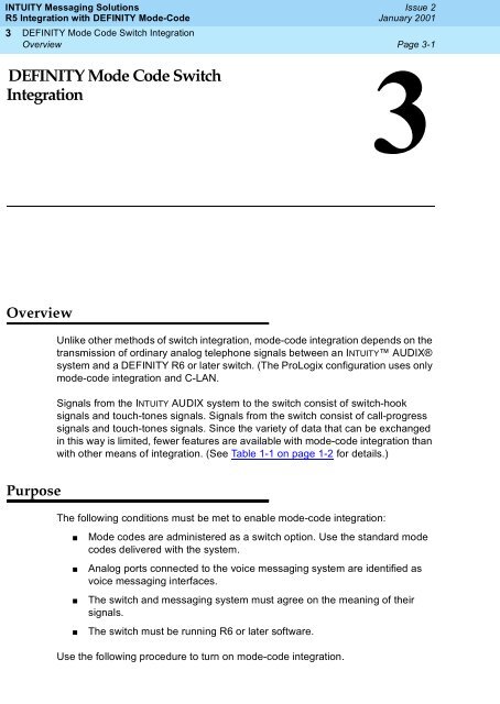
3 DEFINITY Mode Code Switch Integration - Avaya Support
3 DEFINITY Mode Code Switch Integration - Avaya Support
3 DEFINITY Mode Code Switch Integration - Avaya Support

Create successful ePaper yourself
Turn your PDF publications into a flip-book with our unique Google optimized e-Paper software.
INTUITY Messaging SolutionsR5 <strong>Integration</strong> with <strong>DEFINITY</strong> <strong>Mode</strong>-<strong>Code</strong>3<strong>DEFINITY</strong> <strong>Mode</strong> <strong>Code</strong> <strong>Switch</strong> <strong>Integration</strong>Overview3<strong>DEFINITY</strong> <strong>Mode</strong> <strong>Code</strong> <strong>Switch</strong><strong>Integration</strong>Issue 2January 2001Page 3-13OverviewUnlike other methods of switch integration, mode-code integration depends on thetransmission of ordinary analog telephone signals between an INTUITY AUDIX®system and a <strong>DEFINITY</strong> R6 or later switch. (The ProLogix configuration uses onlymode-code integration and C-LAN.Signals from the INTUITY AUDIX system to the switch consist of switch-hooksignals and touch-tones signals. Signals from the switch consist of call-progresssignals and touch-tones signals. Since the variety of data that can be exchangedin this way is limited, fewer features are available with mode-code integration thanwith other means of integration. (See Table 1-1 on page 1-2 for details.)PurposeThe following conditions must be met to enable mode-code integration:■■■■<strong>Mode</strong> codes are administered as a switch option. Use the standard modecodes delivered with the system.Analog ports connected to the voice messaging system are identified asvoice messaging interfaces.The switch and messaging system must agree on the meaning of theirsignals.The switch must be running R6 or later software.Use the following procedure to turn on mode-code integration.
INTUITY Messaging SolutionsR5 <strong>Integration</strong> with <strong>DEFINITY</strong> <strong>Mode</strong>-<strong>Code</strong>3 <strong>DEFINITY</strong> <strong>Mode</strong> <strong>Code</strong> <strong>Switch</strong> <strong>Integration</strong><strong>DEFINITY</strong> <strong>Switch</strong> AdministrationIssue 2January 2001Page 3-2<strong>DEFINITY</strong> <strong>Switch</strong> AdministrationFeature AdministrationEnable <strong>Mode</strong>-<strong>Code</strong> <strong>Integration</strong>Use the switch’s Customer Options form to enable mode code integration.Proceed as follows:1. Enter the command: change system-parameters customer-options andmake sure the G3 Version (on the first line) is set to V6 or later.2. Change to page 2. (Figure 3-1).3. Set the <strong>Mode</strong> <strong>Code</strong> Interface? field on this screen to y.change system-parameters customer-options Page 2 of 4OPTIONAL FEATURESISDN-PRI? n Restrict Call Forward Off Net? ySecondary Data Module? yMalicious Call Trace? nStation and Trunk MSP? n<strong>Mode</strong> <strong>Code</strong> Interface? yTenant Partitioning? nMultifrequency Signaling? y Terminal Trans. Init. (TTI)? nMultimedia Appl. Server Interface (MASI)? nTime of Day Routing? nMultimedia Call Handling (MMCH)? nUniform Dialing Plan? nPersonal Station Access (PSA)? n Usage Allocation Enhancements? nPNC Duplication? nProcessor and System MSP? nPrivate Networking? nWideband <strong>Switch</strong>ing? nWireless? n(NOTE: You must logoff & login to effect the permission changes.)Figure 3-1.<strong>Mode</strong> <strong>Code</strong> Interface EnabledAssign Circuit CardsMake sure your INTUITY AUDIX system is connected to the switch before youcontinue. That is, an on-premises system must be connected as a number ofon-premises stations.Administer each analog port as station type VMI but exactly as if it were a model2500 station. Follow these steps:1. Enter change station port_number
INTUITY Messaging SolutionsR5 <strong>Integration</strong> with <strong>DEFINITY</strong> <strong>Mode</strong>-<strong>Code</strong>3 <strong>DEFINITY</strong> <strong>Mode</strong> <strong>Code</strong> <strong>Switch</strong> <strong>Integration</strong><strong>DEFINITY</strong> <strong>Switch</strong> AdministrationIssue 2January 2001Page 3-3Where port_number is the extension number you assigned to this INTUITYport.The screen of Figure 3-2 appears.2. Enter VMI in the Type field.3. Enter in the Port field the <strong>DEFINITY</strong> location of the port to which you haveconnected this messaging system port.4. Enter in the Name field the name by which this messaging port will beknown. This name must match the name entered in the hunt groupmember assignments, and must include the word AUDIX.5. Fill out the rest of the fields as shown in Figure 3-2. Press ENTER to savethe information.Figure 3-2. Change Station Screen 16. Press NEXTPAGE to move to the second page of the Station screen. Thescreen of Figure 3-3 appears.7. Fill in the fields exactly as illustrated in Figure 3-3.8. Press ENTER to save the information.
INTUITY Messaging SolutionsR5 <strong>Integration</strong> with <strong>DEFINITY</strong> <strong>Mode</strong>-<strong>Code</strong>3 <strong>DEFINITY</strong> <strong>Mode</strong> <strong>Code</strong> <strong>Switch</strong> <strong>Integration</strong><strong>DEFINITY</strong> <strong>Switch</strong> AdministrationIssue 2January 2001Page 3-4Figure 3-3. Change Station Screen 29. Press NEXTPAGE to move to the third page of the Station screen (Figure3-4).Figure 3-4. Change Station Screen 310. Fill out this screen as instructed in the <strong>DEFINITY</strong> documents.11. Press ENTER to save the information.
.INTUITY Messaging SolutionsR5 <strong>Integration</strong> with <strong>DEFINITY</strong> <strong>Mode</strong>-<strong>Code</strong>3 <strong>DEFINITY</strong> <strong>Mode</strong> <strong>Code</strong> <strong>Switch</strong> <strong>Integration</strong><strong>DEFINITY</strong> <strong>Switch</strong> AdministrationIssue 2January 2001Page 3-5Assign the Hunt GroupYou must identify each Intuity AUDIX system voice port as a member of one calldistribution or switch group, also called a hunt group. This group is a set of analogports on the switch that connects subscribers and callers to the Intuity AUDIXsystem by distributing new calls to idle ports. For example, when a caller dials theIntuity AUDIX system number to retrieve voice messages, the hunt group receivesthe call and sends it to the first available port. See the appropriate switchdocumentation for more information about call distribution groups.Use the following procedure to place the voice ports into a hunt group starting withport 1:1. Enter add hunt-group hunt group number at the enter commandprompt on the SAT.The system displays the Hunt Group screen (Figure 3-5).See Worksheet C, in Chapter 2, ‘‘<strong>Switch</strong> <strong>Integration</strong> Planning’’ for the huntgroup number. You also can enter add hunt-group next to add a huntgroup with a number that is one higher than the previous hunt groupadd hunt-group 10 Page 1 of 6HUNT GROUPucdGroup Name: MAP5P AUDIXGroup Number:10 Group Extension: 12000 Group Type:MM Early Answer? n Skill? n ACD? nQueue? yVector? nSecurity <strong>Code</strong>: Night Service Destination: COR: 1ISDN Caller Disp: Coverage Path: TN:1Expected Call Handling Time (sec):180Queue Length: 16Calls Warning Threshold:Calls Warning Port:Time Warning Threshold:Time Warning Port:Figure 3-5. Sample Hunt Group Screen, Page 12. Use Table 3-1 to enter the correct values in the fields on page 1 of the HuntGroup screen.
INTUITY Messaging SolutionsR5 <strong>Integration</strong> with <strong>DEFINITY</strong> <strong>Mode</strong>-<strong>Code</strong>3 <strong>DEFINITY</strong> <strong>Mode</strong> <strong>Code</strong> <strong>Switch</strong> <strong>Integration</strong><strong>DEFINITY</strong> <strong>Switch</strong> AdministrationIssue 2January 2001Page 3-7FieldCOR?Vector?ISDN Caller Disp:Coverage Path:Queue Length:Description and InstructionsEnter the Class of Restriction number listed onWorksheet C in Chapter 2, ‘‘<strong>Switch</strong> <strong>Integration</strong>Planning’’.Enter nEnter grp-name or mbr-name to specify whether thehunt group name or member name will be sent to theoriginating subscriber. Use the hunt group name formost applications. This field is required when theISDN-PRI option on the switch System-ParametersCustomer-Options screen is enabled. If ISDN-PRI isnot enabled, leave the field blank. See Worksheet Cin Chapter 2, ‘‘<strong>Switch</strong> <strong>Integration</strong> Planning’’ for thecorrect value.Leave this field blank. If you enter a coverage path,the switch send a call the coverage point. This mayinterfere with the Intuity AUDIX system.If you entered y in the Queue field, you must enter aqueue length here.NOTE:Use a queue length equal to the number ofvoice ports configured for the Intuity AUDIXsystem.Calls WarningThreshold:Time WarningThreshold:Calls WarningPort:Time WarningPort:Leave this field blank.Leave this field blank.Leave this field blank.Leave this field blank.3. After you enter the correct information in each field, press "1. to savethe information.The system refreshes the screen.4. Press to move to page 2 of the Hunt Group screen (Figure 3-7).
INTUITY Messaging SolutionsR5 <strong>Integration</strong> with <strong>DEFINITY</strong> <strong>Mode</strong>-<strong>Code</strong>3 <strong>DEFINITY</strong> <strong>Mode</strong> <strong>Code</strong> <strong>Switch</strong> <strong>Integration</strong><strong>DEFINITY</strong> <strong>Switch</strong> AdministrationIssue 2January 2001Page 3-8HUNT GROUPMessage Center: noneLWC Reception: noneFirst Announcement Extension:First Announcement Delay (sec):Figure 3-6. Sample Hunt Group Screen, Page 2Fill out page 2 as shown. Enter none into the Message Center field, andagain into the LWC Reception field. Leave the other fields blank.5. After you enter the correct information in each field, press "1. to savethe information.The system refreshes the screen.6. Press ":1,Ã to move to page 3 of the Hunt Group screen (Figure 3-7).(Figure 3-7) shows sample hunt group member assignments for the R6csiswitch. You must assign the Intuity AUDIX voice port extensions asmembers of the hunt group.Page 3 of 10HUNT GROUPGroup Number: 10 Group Extension: 12000 Group Type: ucdGroup Member AssignmentsExt Name Ext Name Ext Name1: 12001 AUDIX 1 14: 12014 AUDIX 14 27: ____2: 12002 AUDIX 2 15: 12015 AUDIX 15 28: ____3: 12003 AUDIX 3 16: 12016 AUDIX 16 29: ____4: 12004 AUDIX 4 17: ____ 30: ____5: 12005 AUDIX 5 18: ____ 31: ____6: 12006 AUDIX 6 19: ____ 32: ____7: 12007 AUDIX 7 20: ____ 33: ____8: 12008 AUDIX 8 21: ____ 34: ____9: 12009 AUDIX 9 22: ____ 35: ____10: 12010 AUDIX 10 23: ____ 36: ____11: 12011 AUDIX 11 24: ____ 37: ____12: 12012 AUDIX 12 25: ____ 38: ____13: 12013 AUDIX 13 26: ____ 39: ____40: ____Figure 3-7. Sample Hunt Group Screen, Page 3
INTUITY Messaging SolutionsR5 <strong>Integration</strong> with <strong>DEFINITY</strong> <strong>Mode</strong>-<strong>Code</strong>3 <strong>DEFINITY</strong> <strong>Mode</strong> <strong>Code</strong> <strong>Switch</strong> <strong>Integration</strong><strong>DEFINITY</strong> <strong>Switch</strong> AdministrationIssue 2January 2001Page 3-97. Enter the Intuity AUDIX voice port extensions as group members. UseTable 3-2 to complete the hunt group assignments.NOTE:Enter the ports you configured for the Intuity AUDIX system. Do notenter voice port extensions that belong to other systems.1‡kÌÝžŠXkÌžÂÎÌš@•kÅÌbžÌšžÎÌbŠÅ‘@àÌÞ‡Š‘kÌàž×Ì@ÂkÌ@bbŠšÌ·k̇ךÎÌž×Ì•k•NkÂŲÌ1‡kÌškßÎÌΊ•kÌàž×Ì@XXkÅÅÌ·kÌךÎÌž×ÌÅXÂkkš_Ìàž×ÌÅkkÌ·kÌš@•kŲTable 3-2.FieldHunt Group Screen Group Member Assignments EntriesDescriptionGroup Number:Group Extension:Group Type:ExtNameThis is a display-only field that shows the groupnumber assigned on page 1 of the Hunt Groupscreen (Figure 3-5).This is a display-only field that shows the groupextension assigned on page 1 of the Hunt Groupscreen (Figure 3-5).This is a display-only field that shows the group typeassigned on page 1 of the Hunt Group screen (Figure3-5).Enter the extensions of each Intuity AUDIX voiceports. Enter the extensions in the same order theextensions were assigned to the voice ports. Theorder must match the order on the Intuity AUDIXsystem Voice Equipment Assignment screen. SeeWorksheet B, in Chapter 2, ‘‘<strong>Switch</strong> <strong>Integration</strong>Planning’’ for a list of voice port extensions.This is a display-only field. The voice port namesdisplay the next time you access the Hunt Groupscreen.8. After you enter the Intuity AUDIX voice port extensions, press "1. tosave the information.The system refreshes the screen.9. Press Ã" to exit the Hunt Group screen and return to the entercommand prompt.You use the Group Number of the Intuity AUDIX hunt group when you assign acall coverage path for the system subscribers. The hunt group number serves asthe coverage point for incoming Intuity AUDIX calls. You will complete the
INTUITY Messaging SolutionsR5 <strong>Integration</strong> with <strong>DEFINITY</strong> <strong>Mode</strong>-<strong>Code</strong>3 <strong>DEFINITY</strong> <strong>Mode</strong> <strong>Code</strong> <strong>Switch</strong> <strong>Integration</strong><strong>DEFINITY</strong> <strong>Switch</strong> AdministrationIssue 2January 2001Page 3-10coverage path assignment procedure in Chapter 4, ‘‘Cut-to-ServiceAdministration’’.Set System ParametersSeven system parameters determine how the system will send mode codes.These are the four mode codes themselves (in the form of touch-tones signals)and three time durations associated with their transmission.These options must match the transmission qualities of your integrated voicemessaging system. Furthermore, the default entries match the INTUITY AUDIXdefaults. For these reasons, do not change the parameters from their defaults foryour INTUITY AUDIX system unless absolutely necessary to meet pre-existing dialplan settings.1. Enter change system-parameters - mode codesThe system displays the Default <strong>Mode</strong> <strong>Code</strong> Settings screen (Figure 3-8).2. The Direct Inside Access field alerts the voice messaging systemthat it is about to get a call from a number that is administered on theswitch. The default delimiter is # and the default code is 00. Set the modecode to match the one administered on your voice messaging system.3. The Direct Dial Access-Trunk field alerts the voice messagingsystem that it is about to get a call from outside of the switching system.The default delimiter is # and the default code is 01. Set the mode code tomatch the one administered on your voice messaging system.4. The Internal Coverage field alerts the voice messaging system that itis required to cover a call from a number that is administered on the switch.The default delimiter is # and the default code is 02. Set the mode code tomatch the one administered on your voice messaging system.5. The External Coverage field alerts the voice messaging system that itis required to cover a call from outside of the switching system. The defaultdelimiter is # and the default code is 03. Set the mode code to match theone administered on your voice messaging system.6. DTMF DURATION-ON field sets the number of milliseconds a touch-tonedigit will be left on when the switch signals the voice messaging system.The default duration is 100 ms. Set the duration to one that will berecognized as a single digit by your voice messaging system.7. DTMF DURATION-OFF field sets the interval in milliseconds to be expectedbetween touch-tones signals when the switch signals the voice messagingsystem. The default interval is 100 ms. Set the interval to one that will berecognized as such by your voice messaging system.8. Sending Delay field is the interval that passes after switch informationis sent. The default interval is 100 ms. Set the interval to one long enoughto be recognized by your voice messaging system.
.INTUITY Messaging SolutionsR5 <strong>Integration</strong> with <strong>DEFINITY</strong> <strong>Mode</strong>-<strong>Code</strong>3 <strong>DEFINITY</strong> <strong>Mode</strong> <strong>Code</strong> <strong>Switch</strong> <strong>Integration</strong>Intuity AUDIX AdministrationIssue 2January 2001Page 3-11MODE CODE RELATED SYSTEM PARAMETERSMODE CODES (FROM SWITCH TO VMS)Direct Inside Access#00___Direct Dial Access - Trunk #01___Internal Coverage #02___External Coverage #03___OTHER RELATED PARAMETERSDTMF DURATION ON(msec): 100 OFF(msec): 100 Sending Delay(msec): 100Figure 3-8.Default <strong>Mode</strong> <strong>Code</strong> SettingsIntuity AUDIX AdministrationOverviewAdministering the Intuity AUDIX system for switch integration requires usingwindows in the telephony and call data interfaces to perform the procedures listedin Table 3-3.Complete the procedures in the order specified.Table 3-3.Task Procedure MatrixOrder Procedure Window1. ‘‘Verifying the Country and <strong>Switch</strong>’’ <strong>Switch</strong> Selection2. ‘‘Setting the MWI Device Assignments’’ Device Assignment3. ‘‘Setting the Dial Plan Translations’’ Dial Plan TranslationContinued on next page
INTUITY Messaging SolutionsR5 <strong>Integration</strong> with <strong>DEFINITY</strong> <strong>Mode</strong>-<strong>Code</strong>3 <strong>DEFINITY</strong> <strong>Mode</strong> <strong>Code</strong> <strong>Switch</strong> <strong>Integration</strong>Intuity AUDIX AdministrationIssue 2January 2001Page 3-12Permissions for WindowsThe sa login can view all the windows used in these procedures but cannotchange any values for parameters. The craft, remote maintenance (tsc), and rootlogins can set values for parameters in all windows.Other Windows Used for <strong>Switch</strong> <strong>Integration</strong>Some windows in the telephony and call data interfaces used for switchintegration can be viewed by the sa and craft logins, but require tsc loginpermissions to change the values for parameters. These windows are used onlyin troubleshooting scenarios involving an <strong>Avaya</strong>, Inc. service representative andare therefore not described here.Stopping and Restarting the Voice SystemIf you change or enter parameters on any of the windows used for switchintegration, you must stop and then restart the system for your changes to beincorporated into call processing.Stopping the Voice SystemStop the voice system. See the procedures for stopping the voice system in‘‘Stopping and Starting the Voice System’’ on page 3-23.Assigning Service to Voice ChannelsComplete this procedure to assign AUDIX to all voice channels.1. Start at the <strong>Avaya</strong> INTUITY Main Menu (Figure 3-11).
INTUITY Messaging SolutionsR5 <strong>Integration</strong> with <strong>DEFINITY</strong> <strong>Mode</strong>-<strong>Code</strong>3 <strong>DEFINITY</strong> <strong>Mode</strong> <strong>Code</strong> <strong>Switch</strong> <strong>Integration</strong>Intuity AUDIX AdministrationIssue 2January 2001Page 3-13Figure 3-9.<strong>Avaya</strong> INTUITY Main Menu2. Select> Voice System Administration> Voice Equipment3. Press F8 (Actions).The system displays the Actions menu.4. Select> Assign/Change> PBX Extension to Channel5. Assign extension numbers to all voice channels that are to be in use. (Besure to press SAVE after each such assignment.)6. Press CANCEL , if necessary, to return to the Assign/Change window.>ÌServices to Channels
INTUITY Messaging SolutionsR5 <strong>Integration</strong> with <strong>DEFINITY</strong> <strong>Mode</strong>-<strong>Code</strong>3 <strong>DEFINITY</strong> <strong>Mode</strong> <strong>Code</strong> <strong>Switch</strong> <strong>Integration</strong>Intuity AUDIX AdministrationIssue 2January 2001Page 3-147. Type all channel numbers into the Channel Numbers: field. Enter AUDIXinto the Service Name: field. This assigns the AUDIX service to allchannels.8. Press SAVE , then CANCEL to return to the Assign/Change menu.9. Select> Channels to GroupsNOTE:The platform comes with a default setting of channel group to 2. Thismay be sufficient for most applications. Note the group number onwhich you decide. You will need this number for switch interfaceadministration.10. Assign channels to the selected groups.11. Press CANCEL , several times to return to the Voice Administration menu.12. Select> Number Services> Assign Number Service13. Enter any in both the called number and the calling number fields.14. Select or enter AUDIX in the Service Name field.15. Use CANCEL to return to the <strong>Avaya</strong> INTUITY Main Menu (Figure 3-9).16. Select> Voice Equipment17. Press the ACTIONS button.18. Select> Assign/Change> State of Voice Equipment
INTUITY Messaging SolutionsR5 <strong>Integration</strong> with <strong>DEFINITY</strong> <strong>Mode</strong>-<strong>Code</strong>3 <strong>DEFINITY</strong> <strong>Mode</strong> <strong>Code</strong> <strong>Switch</strong> <strong>Integration</strong>Intuity AUDIX AdministrationIssue 2January 2001Page 3-15The system displays the Change State of Voice Equipment window (Figure3-10).Figure 3-10.Change State of Voice Equipment Window19. Enter inserv in the New State: field.20. Enter channel in the Equipment: field.21. Enter all in the Equipment Number: field.22. Enter yes in the Change Immediately? field.23. Press F3 (Save).Verifying the Country and <strong>Switch</strong>Use this procedure to check the country and switch for the system’s switchintegration. The selections in this window determine the defaults set in thesystem. If the system does not offer an exact match, contact your remote supportcenter and ask them to select the country the matches the installation conditionsas closely as possible.1. Start at the <strong>Avaya</strong> INTUITY Main Menu and select:> Feature OptionsThe system displays Feature Options window.2. Press F1 (Acknowledge Message).3. Press F7 (<strong>Switch</strong> Select).4. The system displays the <strong>Switch</strong> Selection window (Figure 3-11).
INTUITY Messaging SolutionsR5 <strong>Integration</strong> with <strong>DEFINITY</strong> <strong>Mode</strong>-<strong>Code</strong>3 <strong>DEFINITY</strong> <strong>Mode</strong> <strong>Code</strong> <strong>Switch</strong> <strong>Integration</strong>Intuity AUDIX AdministrationIssue 2January 2001Page 3-16Figure 3-11.<strong>Switch</strong> Selection Window5. Verify that the country and switch parameters match your location. If theydo not, contact your remote support center.6. Press F6 (Cancel) to exit the window.7. Press F6 (Cancel) twice to return to the <strong>Avaya</strong> INTUITY Main Menu.Table 3-4.FieldCountry<strong>Switch</strong><strong>Switch</strong> Selection Window — Field DescriptionsDescription and ValuesSpecifies the country for which the system sets country-specific defaultparameters. Normally the country is factory-preset for your integration.Verify that the country matches your location. If it does not, contact yourremote support center.Specifies the switch for which the system sets default parameters in the calldata interface. Normally the switch type is factory-preset for your integration.Verify that the switch matches your switch. If it does not, contact your remotesupport center.Setting the MWI Device AssignmentsComplete this procedure to assign the channel group number(s) on which thesystem performs MWI updates.The procedure allows you to partition the channelor channels on which MWI updates are performed.To assign a channel group here for MWI updates, you must have alreadyadministered the group using the Channels to Group option under the VoiceEquipment menu. See the installation book for your platform for the procedure.
INTUITY Messaging SolutionsR5 <strong>Integration</strong> with <strong>DEFINITY</strong> <strong>Mode</strong>-<strong>Code</strong>3 <strong>DEFINITY</strong> <strong>Mode</strong> <strong>Code</strong> <strong>Switch</strong> <strong>Integration</strong>Intuity AUDIX AdministrationIssue 2January 2001Page 3-171. Start at the <strong>Avaya</strong> INTUITY Main Menu and select> <strong>Switch</strong> Interface Administration> Call Data Interface Administration> MWI Administration> Device AssignmentThe system displays the first of two screens of the Device Assignmentwindows (Figure 3-12). If the parameters have been previouslyadministered, the system displays the current values instead. To accessthe second screen, press F5 (Next Page). To return to the first screen,press F4 (Prev Page).Figure 3-12.Device Assignment Window2. Enter n in the Link Test (Y/N): field (see Table 3-5).3. Leave the default value in the Link Test Interval: field.4. Enter a switch number in the <strong>Switch</strong> Number field (see Table 3-5).5. Enter a channel group number in the Device ID field (see Table 3-5).6. Press F3 (Save).The system displays the following message:You need to restart the Voice System to make thesechanges active.7. Press F1 (Acknowledge Message).
INTUITY Messaging SolutionsR5 <strong>Integration</strong> with <strong>DEFINITY</strong> <strong>Mode</strong>-<strong>Code</strong>3 <strong>DEFINITY</strong> <strong>Mode</strong> <strong>Code</strong> <strong>Switch</strong> <strong>Integration</strong>Intuity AUDIX AdministrationIssue 2January 2001Page 3-188. Press F6 (Cancel) four times to return to the <strong>Avaya</strong> INTUITY Main Menu.Table 3-5.Device Assignment Window — Field DescriptionsField Description Values<strong>Integration</strong>Link Test(Y/N):Link TestInterval(seconds):<strong>Switch</strong>NumberDevice IDLink TestNumberDisplays the switch selected on the <strong>Switch</strong>Selection window (see Figure 3-11).This field is not used.This field is not used.Number that uniquely identifies the switchand is used to address it. The <strong>Avaya</strong>INTUITY system uses this number todifferentiate between subscribers ondifferent switches.The group number as administered usingthe Channels to Group option under theVoice Equipment menu. Valid range 1through 32.By default, all channels are assigned togroup 2 and outcalling is always done ongroup 2. If, however, channels have beenassigned to another group for MWIupdates, the functionality must be enabledhere.This field is not used.Display only.N/AN/AMaximum of three digits,range 1 to 999. Thisnumber must match theone that identifies theswitch in AUDIXadministration.Group numbers can beseparated by commas(for example 1,3,4,5) orspecified in ranges (forexample 1, 3–5).N/AContinued on next pageSetting MWI Feature Access <strong>Code</strong>sComplete this procedure to set the feature access codes that the messagingsystem sends either to turn on a particular message waiting indicator or to turn itoff. What you should accomplish here is to ensure that the code sent by themessaging system is the one expected by the switch.
INTUITY Messaging SolutionsR5 <strong>Integration</strong> with <strong>DEFINITY</strong> <strong>Mode</strong>-<strong>Code</strong>3 <strong>DEFINITY</strong> <strong>Mode</strong> <strong>Code</strong> <strong>Switch</strong> <strong>Integration</strong>Intuity AUDIX AdministrationIssue 2January 2001Page 3-191. Where a <strong>DEFINITY</strong> system is using mode-code integration,message-waiting indication is handled by the Leave Word Calling (LWC)feature. Discover from the switch administrator what feature access codesthe switch expects to receive for:LWC Send a MessageLWC Cancel a MessageThe <strong>DEFINITY</strong> administrator can find these on the switch’s feature accesscode form.2. Start at the <strong>Avaya</strong> INTUITY Main Menu and select:> <strong>Switch</strong> Interface Administration> Call Data Interface Administration> MWI Administration> MWI Parameters3. The screen that appears should resemble Figure 3-13:Figure 3-13.MWI Parameters Window4. Set the MVI On Prefix to match the LWC Send a Message code set on theswitch.
INTUITY Messaging SolutionsR5 <strong>Integration</strong> with <strong>DEFINITY</strong> <strong>Mode</strong>-<strong>Code</strong>3 <strong>DEFINITY</strong> <strong>Mode</strong> <strong>Code</strong> <strong>Switch</strong> <strong>Integration</strong>Intuity AUDIX AdministrationIssue 2January 2001Page 3-205. Set the MVI Off Prefix to match the LWC Cancel a Message code set onthe switch.6. Press F3 (Save).7. Press F6 (Cancel) four times to return to the <strong>Avaya</strong> INTUITY Main Menu.Setting the Dial Plan TranslationsComplete this procedure to set up the translations to be done on the calling partyidentification (CLI) and called party identification (CP ID) for incoming andoutgoing calls to interface the Intuity AUDIX system and the switch.1. Start at the <strong>Avaya</strong> INTUITY Main Menu and select> <strong>Switch</strong> Interface Administration> Call Data Interface Administration> System Translation Administration> Dial Plan TranslationThe system displays the first of five screens of the Dial Plan Translationwindow (Figure 3-14) with defaults for your integration. If the parametershave been previously administered, the system displays the current valuesinstead.To access the next screen, press F5 (Next Page). To return to theprevious screen, press F4 (Prev Page).
INTUITY Messaging SolutionsR5 <strong>Integration</strong> with <strong>DEFINITY</strong> <strong>Mode</strong>-<strong>Code</strong>3 <strong>DEFINITY</strong> <strong>Mode</strong> <strong>Code</strong> <strong>Switch</strong> <strong>Integration</strong>Intuity AUDIX AdministrationIssue 2January 2001Page 3-21Figure 3-14.Dial Plan Translation Window2. Enter the INTUITY extension length in the INTUITY Extension Length:field (see Table 3-6).3. Enter the <strong>Switch</strong> network access code in the <strong>Switch</strong> Network Access<strong>Code</strong>: field (see Table 3-6).4. Leave the <strong>Switch</strong> Prefix field blank.5. Enter the switch start extension in the <strong>Switch</strong> Start Ext. field (seeTable 3-6).6. Enter the switch end extension in the <strong>Switch</strong> End Ext. field (see Table3-6).7. Enter the INTUITY prefix in the INTUITY Prefix field (see Table 3-6).8. Enter the switch number in the <strong>Switch</strong> Number field (see Table 3-6).9. Enter n in the Remote [Y/N] field (see Table 3-6).10. Repeat Steps 4 through 9 for the remaining translations. (See theexamples following Table 3-6.)11. Press F3 (Save).The system displays the following message:You need to restart the Voice System to make thesechanges active.12. Press F1 (Acknowledge Message).13. Press F6 (Cancel) four times to return to the <strong>Avaya</strong> INTUITY Main Menu.
INTUITY Messaging SolutionsR5 <strong>Integration</strong> with <strong>DEFINITY</strong> <strong>Mode</strong>-<strong>Code</strong>3 <strong>DEFINITY</strong> <strong>Mode</strong> <strong>Code</strong> <strong>Switch</strong> <strong>Integration</strong>Intuity AUDIX AdministrationIssue 2January 2001Page 3-22Table 3-6.Dial Plan Translation Window— Field DescriptionsField Description Values<strong>Integration</strong>INTUITYExtensionLength<strong>Switch</strong>NetworkAccess <strong>Code</strong><strong>Switch</strong>Prefix<strong>Switch</strong>Start Ext.<strong>Switch</strong> EndExt.INTUITYPrefix<strong>Switch</strong>NumberRemote[Y/N]Displays the switch selected on the <strong>Switch</strong>Selection window (see Figure 3-11).Specifies the number of digits in the dialplan.Specifies the code dialed to reach thenetwork. For example, you might dial 9 firstto reach an outside line.Specifies the initial part of the code sent bythe switch as part of the call information.Specifies the first extension number in therange of allowed extension numbers.Specifies the last extension number in therange of allowed extension numbers.Specifies the digits that prefix the INTUITYmailbox numbers.Number that uniquely identifies the switchand is used to address it. The Intuity AUDIXsystem uses this number to differentiatebetween subscribers on different switches.Specifies whether the administered switchnamed in the <strong>Switch</strong> Number field is aremote switch on the network or a localswitch.Display only.3 to 10 integers.The number must be thesame as the number ofdigits administered for theINTUITY prefix combinedwith the number of digitsfor the (start or end)extension number.Not used in mode-codeintegration. Leave thisfield blank.Not used in mode-codeintegration. Leave thisfield blank.The number of digitsspecified for the start andend extension numbersmust be identical. Forexample, to specify therange 200–3999, enter:■ Start extension 0200■ End extension 3900Not used in mode-codeintegration. Leave thisfield blank.Maximum of three digits,range 1–999. Thisnumber must match theone that identifies theswitch in AUDIXadministration.Enter n for mode-codeintegration.Continued on next page
INTUITY Messaging SolutionsR5 <strong>Integration</strong> with <strong>DEFINITY</strong> <strong>Mode</strong>-<strong>Code</strong>3 <strong>DEFINITY</strong> <strong>Mode</strong> <strong>Code</strong> <strong>Switch</strong> <strong>Integration</strong>Intuity AUDIX AdministrationIssue 2January 2001Page 3-23ExampleThe following example illustrates entries used for the common scenario wherethere is a single switch connection and fixed-length switch subscriber extensions.Table 3-7.INTUITY extension length = 4<strong>Switch</strong>Prefix<strong>Switch</strong>Start Ext.<strong>Switch</strong>EndExt.INTUITYPrefix<strong>Switch</strong>ID2000 9999 1 NRemote[Y/N]Stopping and Starting the Voice SystemTo execute any changes you have made to the switch integration administrationwindows in the procedures in this chapter, you must stop and then restart thevoice system.! CAUTION:Only stop the voice system when it is absolutely necessary. All calls inprogress will be disconnected. Subscribers calling the AUDIX system willhear a fast busy signal. Callers sent to AUDIX coverage will hear ringing withno answer.Complete this procedure to stop and restart the voice system.1. Start at the <strong>Avaya</strong> INTUITY Main Menu (Figure 3-9) and select> Customer/Services Administration> System Management> System Control> Stop Voice SystemNOTE:Be sure to select Stop Voice System. Do not select ShutdownVoice System.The system displays the Wait Time window (Figure 3-15).
INTUITY Messaging SolutionsR5 <strong>Integration</strong> with <strong>DEFINITY</strong> <strong>Mode</strong>-<strong>Code</strong>3 <strong>DEFINITY</strong> <strong>Mode</strong> <strong>Code</strong> <strong>Switch</strong> <strong>Integration</strong>Intuity AUDIX AdministrationIssue 2January 2001Page 3-24Figure 3-15.Wait Time Window2. Enter a time between 60 and 600 seconds as the time to wait for calls inPress F3 (Save).The system displays the following message:The voice System has stoppedPress ENTER to continue...NOTE:The system waits until all calls in progress disconnect before stopping thevoice system.3. Press ENTER .The system displays the System Control menu again (Figure 3-16).Figure 3-16.System Control Menu4. Select> Start Voice SystemThe system displays the following message:Startup of the Voice System is completeHit Acknowledge key to continue...5. Press F1 (Acknowledge Message).6. The system redisplays the System Control window (Figure 3-16).7. Press F6 (Cancel) several times to return to the <strong>Avaya</strong> INTUITY Main Menu.