The Effect of Pad Grooving and Texturing on CMP Process ...
The Effect of Pad Grooving and Texturing on CMP Process ...
The Effect of Pad Grooving and Texturing on CMP Process ...
- No tags were found...

Create successful ePaper yourself
Turn your PDF publications into a flip-book with our unique Google optimized e-Paper software.
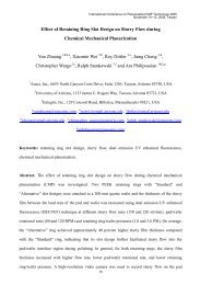
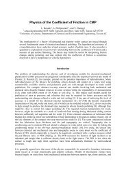
(1) Slurry Dispensed <strong>on</strong>to <str<strong>on</strong>g>Pad</str<strong>on</strong>g>- Texture c<strong>on</strong>trols slurry retenti<strong>on</strong> <strong>on</strong> platen- Grooves influence initial film thickness(5) Slurry Held by <str<strong>on</strong>g>Pad</str<strong>on</strong>g> is Recycled- Texture c<strong>on</strong>trols slurry retenti<strong>on</strong> <strong>on</strong> platen- Grooves protract residence time <strong>on</strong> padΩ WaferΩ Platen(4) <str<strong>on</strong>g>Pad</str<strong>on</strong>g>-Wafer-Slurry C<strong>on</strong>tact- Texture c<strong>on</strong>trols material removal(2) Slurry Spreads across <str<strong>on</strong>g>Pad</str<strong>on</strong>g>- Grooves/texture balance c<strong>on</strong>trols- <str<strong>on</strong>g>Pad</str<strong>on</strong>g> texture affects wetting anglewafer-scale transport- Grooves dictate spread directi<strong>on</strong>(3) <str<strong>on</strong>g>Pad</str<strong>on</strong>g> Draws Slurry under Wafer- <str<strong>on</strong>g>Pad</str<strong>on</strong>g> texture moves slurry against drag <str<strong>on</strong>g>of</str<strong>on</strong>g> wafer- Grooves augment slurry carrying capacityFigure 1: Role <str<strong>on</strong>g>of</str<strong>on</strong>g> <str<strong>on</strong>g>Pad</str<strong>on</strong>g> Grooves <str<strong>on</strong>g>and</str<strong>on</strong>g> Texture in <strong>CMP</strong> Slurry Flow <str<strong>on</strong>g>and</str<strong>on</strong>g> Transport<str<strong>on</strong>g>The</str<strong>on</strong>g> present work compares several groove arrays <str<strong>on</strong>g>and</str<strong>on</strong>g> texture variants to examine theresp<strong>on</strong>se <str<strong>on</strong>g>of</str<strong>on</strong>g> transport phenomena in the pad-wafer gap. Predicted wafer pr<str<strong>on</strong>g>of</str<strong>on</strong>g>iles areexamined to quantify the potential impact <str<strong>on</strong>g>of</str<strong>on</strong>g> pad grooving <str<strong>on</strong>g>and</str<strong>on</strong>g> texturing <strong>on</strong> processperformance <str<strong>on</strong>g>and</str<strong>on</strong>g> to identify features that favor efficient slurry mixing <str<strong>on</strong>g>and</str<strong>on</strong>g> heat removal,that in turn lead to uniform defect-free polishing.2. BackgroundWafer-scale <strong>CMP</strong> models published pre-2003 represent transport in the pad-wafergap using the Reynolds hydrodynamic equati<strong>on</strong> [1,2,3], sometimes with “flow factors”to account for the effect <str<strong>on</strong>g>of</str<strong>on</strong>g> rough surfaces <strong>on</strong> the c<strong>on</strong>veyed flow <str<strong>on</strong>g>of</str<strong>on</strong>g> slurry [4]. Whileusually adequate for predicting global velocity <str<strong>on</strong>g>and</str<strong>on</strong>g> temperature fields under the waferfor an ungrooved <strong>CMP</strong> pad, the lubricati<strong>on</strong> approximati<strong>on</strong> cannot capture the sharpdisparities in transport fields that prevail <strong>on</strong> grooved pads [5] nor inertial flow effectswithin the texture <str<strong>on</strong>g>of</str<strong>on</strong>g> a pad that may affect polishing [6].A porous-media flow approach was introduced [7] in 2003 to characterize <strong>CMP</strong> padsby forcing fluid over the surface as compressed between two flat plates <str<strong>on</strong>g>and</str<strong>on</strong>g> measuringthe resulting pressure loss pr<str<strong>on</strong>g>of</str<strong>on</strong>g>iles. <str<strong>on</strong>g>Pad</str<strong>on</strong>g> texture is thus quantified as a populati<strong>on</strong> <str<strong>on</strong>g>of</str<strong>on</strong>g>flow obstacles, which gives a more realistic picture <str<strong>on</strong>g>of</str<strong>on</strong>g> pad-slurry interacti<strong>on</strong> under thewafer in a typical polish process (Fig. 2). Applicati<strong>on</strong> <str<strong>on</strong>g>of</str<strong>on</strong>g> the Ergun equati<strong>on</strong> [8] to thepressure pr<str<strong>on</strong>g>of</str<strong>on</strong>g>iles produces “porous-media” texture descriptors suitable for direct use incomputati<strong>on</strong>al fluid dynamics (CFD) simulati<strong>on</strong>s.Subsequent CFD studies using flow-based texture descriptors [9,10] have shown thattransport fields in the pad-wafer gap may depart significantly from those predicted bylubricati<strong>on</strong> theory. For example, it has been found that pad texture interacts str<strong>on</strong>glywith pad-wafer relative velocity to determine how effectively fresh slurry replacesspent slurry [11]. In additi<strong>on</strong>, grooves mitigate the effect <str<strong>on</strong>g>of</str<strong>on</strong>g> wafer tilt <str<strong>on</strong>g>and</str<strong>on</strong>g> curvature<strong>on</strong> fluid pressures in the pad-wafer gap [5]. As a result, dual-axis polisher modelsthat omit grooves overestimate the angles <str<strong>on</strong>g>of</str<strong>on</strong>g> attack <str<strong>on</strong>g>and</str<strong>on</strong>g> pitch required to satisfy force<str<strong>on</strong>g>and</str<strong>on</strong>g> torque equilibria <strong>on</strong> a gimbaled wafer.32
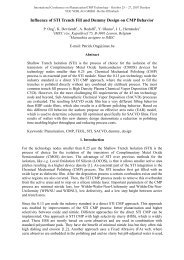
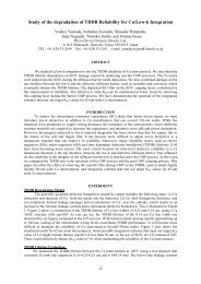
Gap HeightHCharacteristicLength D EVoid Fracti<strong>on</strong>εHFluid In, WTop Plate withPressure Sensors<strong>CMP</strong> <str<strong>on</strong>g>Pad</str<strong>on</strong>g>SampleHr 0rp(r)WaferUniform PressureBottom PlateFluid Out<str<strong>on</strong>g>Pad</str<strong>on</strong>g>RadialPressurePr<str<strong>on</strong>g>of</str<strong>on</strong>g>ilesp(r)p 0FluidInExperimentalDataCFD Resultfor Chosenε <str<strong>on</strong>g>and</str<strong>on</strong>g> D EFluidOutSlurry Flow0r 0rFigure 2: Porous-Media Representati<strong>on</strong><str<strong>on</strong>g>of</str<strong>on</strong>g> <strong>CMP</strong> <str<strong>on</strong>g>Pad</str<strong>on</strong>g> Asperity LayerFigure 3: Flow-Based <str<strong>on</strong>g>Pad</str<strong>on</strong>g> TextureCharacterizati<strong>on</strong> Experiment3. Experimental Apparatus <str<strong>on</strong>g>and</str<strong>on</strong>g> Data Analysis<str<strong>on</strong>g>The</str<strong>on</strong>g> flow-based texture characterizati<strong>on</strong> apparatus, detailed elsewhere [7], c<strong>on</strong>sists<str<strong>on</strong>g>of</str<strong>on</strong>g> two 200-mm diameter flat plates between which a pad sample <str<strong>on</strong>g>of</str<strong>on</strong>g> the same size ismounted (Fig. 3). A hydraulic lift applies a c<strong>on</strong>trolled pressure to raise the bottomplate <str<strong>on</strong>g>and</str<strong>on</strong>g> bring the pad into c<strong>on</strong>tact with the top plate. Fluid enters through a centralinlet in the top plate, flows radially outward through the compressed asperity layer <str<strong>on</strong>g>of</str<strong>on</strong>g>the sample, <str<strong>on</strong>g>and</str<strong>on</strong>g> exits at the perimeter. A polar sensor grid <strong>on</strong> the top plate registersthe pressure field p(r,θ) due to fluid flow over the pad surface. Sensors accurate to0.1 psi are located every 9.5 mm al<strong>on</strong>g twelve equally-spaced radii. Pressure loss dataare taken at multiple downforces within the 0.5 to 8-psi range <str<strong>on</strong>g>of</str<strong>on</strong>g> industrial <strong>CMP</strong>practice <str<strong>on</strong>g>and</str<strong>on</strong>g> at several flow rates spanning the range <str<strong>on</strong>g>of</str<strong>on</strong>g> viscous <str<strong>on</strong>g>and</str<strong>on</strong>g> inertial fluid forcesin commercial polishers. Plotting the difference <str<strong>on</strong>g>of</str<strong>on</strong>g> p 2 between two radii against fluidflow rate determines the asperity layer flow resistance based <strong>on</strong> the Ergun equati<strong>on</strong> [6]:p ( r+ BW2223) − p(r10) = AW. (1)Thus A <str<strong>on</strong>g>and</str<strong>on</strong>g> B are c<strong>on</strong>stants for a given pad surface compressed under a fixed downforce.Generally the AW (viscous) term is larger, <str<strong>on</strong>g>and</str<strong>on</strong>g> A is taken as the surface flow resistance.4. Experimental Results <str<strong>on</strong>g>and</str<strong>on</strong>g> Discussi<strong>on</strong>Fig. 4 shows fluid pressure drops in the pad-plate gap for three roughness variants <str<strong>on</strong>g>of</str<strong>on</strong>g>a hard (Type III [12]) polyurethane pad [6]. At 1.2 psi downforce, pressure drop <str<strong>on</strong>g>and</str<strong>on</strong>g>surface flow resistance (slope <str<strong>on</strong>g>of</str<strong>on</strong>g> ∆(p 2 ) versus W) are similar across all roughnesses.At 3 psi <str<strong>on</strong>g>and</str<strong>on</strong>g> higher, the low-roughness pad resistance becomes progressively largerthan the mid-roughness, which remains slightly larger than the high-roughness.Lower surface flow resistance at higher roughness was also observed for s<str<strong>on</strong>g>of</str<strong>on</strong>g>t pads [13]<str<strong>on</strong>g>and</str<strong>on</strong>g> illustrates that rougher surfaces have larger void fracti<strong>on</strong>s. However in s<str<strong>on</strong>g>of</str<strong>on</strong>g>t padsthe roughness influence was str<strong>on</strong>g at 1-2 psi <str<strong>on</strong>g>and</str<strong>on</strong>g> weak at 4-6 psi (where it wastheorized that surface voids were flattened), while in Fig. 4 the effect is str<strong>on</strong>ger athigher downforce. <str<strong>on</strong>g>The</str<strong>on</strong>g> c<strong>on</strong>trast highlights two different regimes in the c<strong>on</strong>tinuum <str<strong>on</strong>g>of</str<strong>on</strong>g>pad compliance. Being stiffer, the hard pad is less compliant at lower downforce <str<strong>on</strong>g>and</str<strong>on</strong>g>surface roughness effects are minimal, while compliance increases at higher downforce<str<strong>on</strong>g>and</str<strong>on</strong>g> roughness begins to manifest in the flow resistance. Under similar downforces as<str<strong>on</strong>g>of</str<strong>on</strong>g>t pad is almost fully compliant. Surface void deformati<strong>on</strong> proposed in s<str<strong>on</strong>g>of</str<strong>on</strong>g>t padslikely occurs in hard pads <strong>on</strong>ly at very high downforces uncomm<strong>on</strong> to <strong>CMP</strong>.33 PacRim-<strong>CMP</strong> 2004
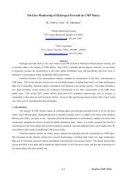
1.2E+101.2E+10DF = 1.2psiLow Mid HighDF = 3.0 psiLow Mid Highp(3) 2 - p(10) 2 , Pa 28.0E+094.0E+09p(3) 2 - p(10) 2 , Pa 28.0E+094.0E+090.0E+000.0 1.0 2.0 3.0W, Fluid Flow Rate, kg/s x 10 60.0E+000.0 1.0 2.0 3.0W, Fluid Flow Rate, kg/s x 10 61.2E+101.2E+10DF = 5.8 psiLow Mid HighDF = 8.0 psiLow Mid Highp(3) 2 - p(10) 2 , Pa 28.0E+094.0E+09p(3) 2 - p(10) 2 , Pa 28.0E+094.0E+090.0E+000.0 1.0 2.0 3.0W, Fluid Flow Rate, kg/s x 10 60.0E+000.0 1.0 2.0 3.0W, Fluid Flow Rate, kg/s x 10 6Figure 4: Surface Flow Resistance for Circular Grooved Hard <str<strong>on</strong>g>Pad</str<strong>on</strong>g> Variants <str<strong>on</strong>g>of</str<strong>on</strong>g> Low, Mid,<str<strong>on</strong>g>and</str<strong>on</strong>g> High Roughness at Four Applied DownforcesFig. 5 summarizes Cu, TEOS, <str<strong>on</strong>g>and</str<strong>on</strong>g> TaNremoval rates for the hard pad roughnessvariants used in a 3-psi <strong>CMP</strong> process [6].<str<strong>on</strong>g>The</str<strong>on</strong>g> observed rates do not correlate withpost-polish pad roughness measurements,but they form a clear <str<strong>on</strong>g>and</str<strong>on</strong>g> linear resp<strong>on</strong>seto surface flow resistance. Highersurface flow resistance implies a largernumber <str<strong>on</strong>g>of</str<strong>on</strong>g> asperities in c<strong>on</strong>tact ornear-c<strong>on</strong>tact with the c<strong>on</strong>fining surface,a state that also favors greater materialremoval rate under a fixed downforce.However removal rate is also affected bypad texture through transport phenomena<str<strong>on</strong>g>and</str<strong>on</strong>g> the resulting distributi<strong>on</strong> <str<strong>on</strong>g>of</str<strong>on</strong>g> heat <str<strong>on</strong>g>and</str<strong>on</strong>g>fresh slurry chemistry under the wafer,as shown in the computati<strong>on</strong>al resultsthat follow.Removal Rate, A 0 /min950820690560430HighRoughnessMidRoughnessLowRoughness3002 2.5 3 3.5 4 4.5<str<strong>on</strong>g>Pad</str<strong>on</strong>g> Surface Flow Resistance,Pa 2 s/kg x 10 9CuTEOSTaNFigure 5: Wafer Polish Results for CircularGrooved Hard <str<strong>on</strong>g>Pad</str<strong>on</strong>g> Variants <str<strong>on</strong>g>of</str<strong>on</strong>g> Low, Mid,<str<strong>on</strong>g>and</str<strong>on</strong>g> High Roughness at 3 psi Downforce5. Computati<strong>on</strong>al ModelEarlier publicati<strong>on</strong>s have presented the CFD model built for a commercial dual-axisrotary <strong>CMP</strong> tool polishing a 200-mm wafer <strong>on</strong> a 508-mm pad. Fixed meshes were usedfor c<strong>on</strong>centric circular grooves [5,7,9] <str<strong>on</strong>g>and</str<strong>on</strong>g> sliding meshes for radial <str<strong>on</strong>g>and</str<strong>on</strong>g> XY [10] <str<strong>on</strong>g>and</str<strong>on</strong>g>spiral grooves [11]. In all cases the flow domain was the thin gap bounded above bythe wafer <str<strong>on</strong>g>and</str<strong>on</strong>g> below by the textured pad areas <str<strong>on</strong>g>and</str<strong>on</strong>g> groove surfaces (Fig. 6). FLUENT6.1 was used to solve the 3D Navier-Stokes <str<strong>on</strong>g>and</str<strong>on</strong>g> c<strong>on</strong>tinuity equati<strong>on</strong>s with a no-slip <str<strong>on</strong>g>and</str<strong>on</strong>g>no-penetrati<strong>on</strong> c<strong>on</strong>diti<strong>on</strong> at the moving pad <str<strong>on</strong>g>and</str<strong>on</strong>g> wafer surfaces <str<strong>on</strong>g>and</str<strong>on</strong>g> a pressure boundary34
at the wafer edge. Fluid cells were used in the grooves <str<strong>on</strong>g>and</str<strong>on</strong>g> porous-media cells in thetextured areas with ε <str<strong>on</strong>g>and</str<strong>on</strong>g> D E values for the subject pad material <str<strong>on</strong>g>and</str<strong>on</strong>g> downforce. <str<strong>on</strong>g>Pad</str<strong>on</strong>g>rotati<strong>on</strong> was 33 rpm; wafer speeds from 12 to 61 rpm were studied. Polish downforcewas 2 or 3 psi in the cases presented here. <str<strong>on</strong>g>Effect</str<strong>on</strong>g>s <str<strong>on</strong>g>of</str<strong>on</strong>g> pad texture were examined byusing measured porous-media parameters (H, ε, <str<strong>on</strong>g>and</str<strong>on</strong>g> D E in Fig. 2) for pads subjected todifferent levels <str<strong>on</strong>g>of</str<strong>on</strong>g> c<strong>on</strong>diti<strong>on</strong>ing to produce surface textures ranging from coarse to fine.Temperature <str<strong>on</strong>g>and</str<strong>on</strong>g> c<strong>on</strong>centrati<strong>on</strong> fields were generated by solving the energy transport<str<strong>on</strong>g>and</str<strong>on</strong>g> mass transport equati<strong>on</strong>s for porous media coupled with the momentum equati<strong>on</strong>s.Fricti<strong>on</strong>al <str<strong>on</strong>g>and</str<strong>on</strong>g> chemical heat source terms [9] were included with a pad thermalc<strong>on</strong>ductivity estimated at 0.30 W/m/K°. C<strong>on</strong>sumpti<strong>on</strong> <str<strong>on</strong>g>of</str<strong>on</strong>g> fresh slurry <str<strong>on</strong>g>and</str<strong>on</strong>g> generati<strong>on</strong><str<strong>on</strong>g>of</str<strong>on</strong>g> polish debris <str<strong>on</strong>g>and</str<strong>on</strong>g> spent slurry were dictated by pseudo-first order surface kineticswith a rate c<strong>on</strong>stant <str<strong>on</strong>g>of</str<strong>on</strong>g> 1.08 x 10 -3 s -1 at 25°C <str<strong>on</strong>g>and</str<strong>on</strong>g> activati<strong>on</strong> energy <str<strong>on</strong>g>of</str<strong>on</strong>g> 10-15 kcal/gmol.20” <str<strong>on</strong>g>Pad</str<strong>on</strong>g><str<strong>on</strong>g>Pad</str<strong>on</strong>g> Edge200 mm WaferArea <str<strong>on</strong>g>of</str<strong>on</strong>g>Detail20” <str<strong>on</strong>g>Pad</str<strong>on</strong>g>Grooves<str<strong>on</strong>g>Pad</str<strong>on</strong>g>CenterShape <str<strong>on</strong>g>of</str<strong>on</strong>g>FluidVolumeΩ WaferLocati<strong>on</strong> <str<strong>on</strong>g>of</str<strong>on</strong>g>Fresh SlurryInfusi<strong>on</strong> Fr<strong>on</strong>t200 mmWafer0.0 sec0.1 sec0.2 sec0.3 secΩ PlatenGap Height43 µmL<str<strong>on</strong>g>and</str<strong>on</strong>g> Area(Porous Cells)0.4 secGroove(Fluid Cells)Figure 6: Computati<strong>on</strong>al Model <str<strong>on</strong>g>of</str<strong>on</strong>g> Slurry Flowbetween 200-mm Wafer <str<strong>on</strong>g>and</str<strong>on</strong>g> Grooved <str<strong>on</strong>g>Pad</str<strong>on</strong>g>Figure 7: CFD Transient Slurry MixingAnalysis for 33 rpm Platen Speed6. Computati<strong>on</strong>al Results <str<strong>on</strong>g>and</str<strong>on</strong>g> Discussi<strong>on</strong><str<strong>on</strong>g>The</str<strong>on</strong>g> impact <str<strong>on</strong>g>of</str<strong>on</strong>g> pad grooving <str<strong>on</strong>g>and</str<strong>on</strong>g> texturing is illustrated via the transient dynamics bywhich fresh slurry displaces spent slurry under the wafer (Fig. 7). At time zero, spentslurry occupies the pad-wafer gap <str<strong>on</strong>g>and</str<strong>on</strong>g> fresh slurry is released at the wafer leading edge.As the pad rotates, the fresh/spent slurry interface proceeds under the wafer where it issubject to the complicating influence <str<strong>on</strong>g>of</str<strong>on</strong>g> wafer rotati<strong>on</strong> <str<strong>on</strong>g>and</str<strong>on</strong>g> the unequal flow resistances<str<strong>on</strong>g>of</str<strong>on</strong>g> grooves <str<strong>on</strong>g>and</str<strong>on</strong>g> l<str<strong>on</strong>g>and</str<strong>on</strong>g> areas. Slurry renewal is gauged at fixed time intervals to comparethe effectiveness <str<strong>on</strong>g>of</str<strong>on</strong>g> different groove <str<strong>on</strong>g>and</str<strong>on</strong>g> texture variants. Were the wafer absent, theinterface would advance at the speed <str<strong>on</strong>g>of</str<strong>on</strong>g> the pad, <str<strong>on</strong>g>and</str<strong>on</strong>g> for a 33-rpm platen the pad-wafergap would infuse with fresh slurry in 0.42 s. Actual renewal times are l<strong>on</strong>ger becauseat many locati<strong>on</strong>s the wafer surface moves more slowly or even in an opposite directi<strong>on</strong>than the pad. Regi<strong>on</strong>s <str<strong>on</strong>g>of</str<strong>on</strong>g> delayed slurry renewal signal slower transport phenomenafavoring locally higher temperature <str<strong>on</strong>g>and</str<strong>on</strong>g> lower c<strong>on</strong>centrati<strong>on</strong> <str<strong>on</strong>g>of</str<strong>on</strong>g> fresh chemistry.Comparis<strong>on</strong> <str<strong>on</strong>g>of</str<strong>on</strong>g> Groove PatternsSlurry mixing dynamics are shown in Figs. 8, 9, 10, <str<strong>on</strong>g>and</str<strong>on</strong>g> 11 for c<strong>on</strong>centric circular,radial, XY grid, <str<strong>on</strong>g>and</str<strong>on</strong>g> spiral groove patterns respectively at 33 rpm platen speed <str<strong>on</strong>g>and</str<strong>on</strong>g> 33rpm wafer speed. In all cases the principal mixing interface advances under the waferas anticipated in Fig. 7, but each groove pattern interacts in a particular way with thedirecti<strong>on</strong> <str<strong>on</strong>g>of</str<strong>on</strong>g> local wafer moti<strong>on</strong> <str<strong>on</strong>g>and</str<strong>on</strong>g> imparts to the flow field a different departure fromrigid-body movement <str<strong>on</strong>g>of</str<strong>on</strong>g> the slurry.35 PacRim-<strong>CMP</strong> 2004
Circular grooves (Fig. 8) lead to a broad b<str<strong>on</strong>g>and</str<strong>on</strong>g> <str<strong>on</strong>g>of</str<strong>on</strong>g> transiti<strong>on</strong>al slurry c<strong>on</strong>centrati<strong>on</strong>with l<strong>on</strong>g <str<strong>on</strong>g>and</str<strong>on</strong>g> distinct trailing wakes in each groove. This flow field results becausethe textured areas act as momentum sources throughout, whereas the grooves can drivefluid <strong>on</strong>ly via drag at the groove walls. Fluid slip in circular grooves is thus a directc<strong>on</strong>sequence <str<strong>on</strong>g>of</str<strong>on</strong>g> their exact <str<strong>on</strong>g>and</str<strong>on</strong>g> c<strong>on</strong>stant alignment with the directi<strong>on</strong> <str<strong>on</strong>g>of</str<strong>on</strong>g> pad rotati<strong>on</strong>.Velocities in the grooves are up to 50% less than in the immediately adjacent l<str<strong>on</strong>g>and</str<strong>on</strong>g> areas,<str<strong>on</strong>g>and</str<strong>on</strong>g> regi<strong>on</strong>s <str<strong>on</strong>g>of</str<strong>on</strong>g> 100% fresh slurry are separated by tracts <str<strong>on</strong>g>of</str<strong>on</strong>g> as low as 55% fresh slurry.Extended wakes form <str<strong>on</strong>g>and</str<strong>on</strong>g> persist al<strong>on</strong>g the line linking the pad <str<strong>on</strong>g>and</str<strong>on</strong>g> wafer centersbecause <strong>on</strong>ly at this locati<strong>on</strong> does the wafer velocity oppose the pad velocity <str<strong>on</strong>g>and</str<strong>on</strong>g> haveno comp<strong>on</strong>ent transverse to the groove to drive mixing in the groove cross-secti<strong>on</strong>.Fresh Slurry Fracti<strong>on</strong>in Plane 5µ below WaferΩ PlatenFreshSlurryFreshSlurryFreshSlurryTexture AreaGrooveSpentSlurryΩ PlatenΩ Wafer Ω WaferSpentSlurrySpentSlurry0.08 sec 0.22 secCase:Table 33 rpmWafer 33 rpmDownforce 2 psiMedium C<strong>on</strong>diti<strong>on</strong>ingFlat 43 µm GapDetail at 0.22 secFigure 8: Slurry Mixing Dynamics in <str<strong>on</strong>g>Pad</str<strong>on</strong>g>-Wafer Gap for C<strong>on</strong>centric Circular GroovesRadial grooves (Fig. 9) create small but distinct jumps in an otherwise very broadb<str<strong>on</strong>g>and</str<strong>on</strong>g> <str<strong>on</strong>g>of</str<strong>on</strong>g> transiti<strong>on</strong>al slurry c<strong>on</strong>centrati<strong>on</strong>. <str<strong>on</strong>g>The</str<strong>on</strong>g> mixing dynamics differ <strong>on</strong>ly marginallyfrom those <str<strong>on</strong>g>of</str<strong>on</strong>g> an ungrooved pad except near the pad center, where the diffusi<strong>on</strong> <str<strong>on</strong>g>of</str<strong>on</strong>g> freshslurry under the wafer proceeds in discrete patches between each pair <str<strong>on</strong>g>of</str<strong>on</strong>g> grooves.<str<strong>on</strong>g>The</str<strong>on</strong>g>re is very little evidence <str<strong>on</strong>g>of</str<strong>on</strong>g> wafer moti<strong>on</strong>. Being oriented perpendicular to the padrotati<strong>on</strong>, radial grooves advance the slurry by positive displacement rather than surfacedrag, forestalling the fluid slip observed with circular grooves especially in the regi<strong>on</strong><str<strong>on</strong>g>of</str<strong>on</strong>g> opposed pad <str<strong>on</strong>g>and</str<strong>on</strong>g> wafer velocities. Extended wakes also cannot form because aradial groove always has a transverse comp<strong>on</strong>ent <str<strong>on</strong>g>of</str<strong>on</strong>g> pad-wafer relative velocity tomotivate top-to-bottom mixing. However this same orientati<strong>on</strong> prevents radialgrooves from relieving pressure extremes developed in the slurry during transit fromthe leading to trailing edge <str<strong>on</strong>g>of</str<strong>on</strong>g> the wafer, leading to a higher tendency for hydroplaning.Fresh Slurry Fracti<strong>on</strong>in Plane 5µ below WaferΩ PlatenΩ Wafer Ω WaferΩ PlatenFreshSlurryFreshSlurrySpentSlurryFreshSlurrySpentSlurrySpentSlurryTexture AreaGroove0.08 sec 0.22 secCase:Table 33 rpmWafer 33 rpmDownforce 2 psiMedium C<strong>on</strong>diti<strong>on</strong>ingFlat 43 µm GapDetail at 0.22 secFigure 9: Slurry Mixing Dynamics in <str<strong>on</strong>g>Pad</str<strong>on</strong>g>-Wafer Gap for Radial Grooves36
Cartesian grid or XY grooves (Fig. 10) achieve a very sharp mixing fr<strong>on</strong>t betweenfresh <str<strong>on</strong>g>and</str<strong>on</strong>g> spent slurry with <strong>on</strong>ly small regi<strong>on</strong>s <str<strong>on</strong>g>of</str<strong>on</strong>g> transiti<strong>on</strong>al c<strong>on</strong>centrati<strong>on</strong> extendinginto groove segments ahead <str<strong>on</strong>g>of</str<strong>on</strong>g> the principal interface. Slurry renewal is efficientbecause XY grooves have a time-variant orientati<strong>on</strong> relative to pad rotati<strong>on</strong> that avoidsthe fluid slip <str<strong>on</strong>g>of</str<strong>on</strong>g> circular grooves, plus interc<strong>on</strong>necti<strong>on</strong>s that limit fluid pressureextremes in the groove network. Moreover, textured areas <str<strong>on</strong>g>and</str<strong>on</strong>g> grooves are physicallyexchanged as the grid rotates, accelerating the process <str<strong>on</strong>g>of</str<strong>on</strong>g> fluid replacement. Detachedisl<str<strong>on</strong>g>and</str<strong>on</strong>g>s <str<strong>on</strong>g>of</str<strong>on</strong>g> relatively fresh slurry downstream <str<strong>on</strong>g>of</str<strong>on</strong>g> the principal interface (circled in Fig.10) reveal that fluid in the bottom <str<strong>on</strong>g>of</str<strong>on</strong>g> the grooves advances ahead <str<strong>on</strong>g>of</str<strong>on</strong>g> that near the wafersurface as the pad turns, <str<strong>on</strong>g>and</str<strong>on</strong>g> is raised by vertical mixing in the groove cross-secti<strong>on</strong>.This underscores the fully 3-D character <str<strong>on</strong>g>of</str<strong>on</strong>g> the flow field in many <strong>CMP</strong> pad grooves.Fresh Slurry Fracti<strong>on</strong>in Plane 5µ below WaferΩ PlatenFreshSlurryFreshSlurryFreshSlurryTexture AreaΩ PlatenΩ WaferΩ WaferSpentSlurrySpentSlurryGrooveSpentSlurry0.08 sec 0.22 secCase:Table 33 rpmWafer 33 rpmDownforce 2 psiMedium C<strong>on</strong>diti<strong>on</strong>ingFlat 43 µm GapDetail at 0.22 secFigure 10: Slurry Mixing Dynamics in <str<strong>on</strong>g>Pad</str<strong>on</strong>g>-Wafer Gap for XY Grid GroovesSpiral grooves (Fig. 11) show a b<str<strong>on</strong>g>and</str<strong>on</strong>g> <str<strong>on</strong>g>of</str<strong>on</strong>g> transiti<strong>on</strong>al c<strong>on</strong>centrati<strong>on</strong> similar in width tothat <str<strong>on</strong>g>of</str<strong>on</strong>g> circular grooves, but with extending mixing regi<strong>on</strong>s appearing in advance <str<strong>on</strong>g>of</str<strong>on</strong>g> theprincipal interface rather than trailing behind it. Relatively fresh slurry projects intothe spent slurry al<strong>on</strong>g every groove immediately after the interface begins from theleading edge. As the interface approaches the trailing edge, detached regi<strong>on</strong>s <str<strong>on</strong>g>of</str<strong>on</strong>g> freshslurry appear downstream in the grooves <str<strong>on</strong>g>and</str<strong>on</strong>g> bridge upstream to meet the interface.This unexpected result illustrates the same slurry tunneling that was observed in <strong>on</strong>lyisolated locati<strong>on</strong>s <str<strong>on</strong>g>of</str<strong>on</strong>g> the XY grid. Both slurry tunneling <str<strong>on</strong>g>and</str<strong>on</strong>g> the forwardly extendedmixing regi<strong>on</strong>s occur because slurry in a groove, up<strong>on</strong> entering the pad-wafer gap,decelerates sharply at the wafer surface due to drag <str<strong>on</strong>g>and</str<strong>on</strong>g> must accelerate in the bottom<str<strong>on</strong>g>of</str<strong>on</strong>g> the groove to maintain volume flow, that is, to satisfy the c<strong>on</strong>tinuity c<strong>on</strong>straint.Fresh Slurry Fracti<strong>on</strong>in Plane 5µ below WaferFreshSlurryΩ PlatenΩ WaferΩ WaferΩ PlatenFreshSlurryDirecti<strong>on</strong><str<strong>on</strong>g>of</str<strong>on</strong>g> WaferVelocityFreshSlurryTexture AreaGrooveSpentSlurrySpentSlurrySpentSlurry0.08 sec 0.22 secCase:Table 33 rpmWafer 33 rpmDownforce 2 psiMedium C<strong>on</strong>diti<strong>on</strong>ingFlat 43 µm GapDetail at 0.22 secFigure 11: Slurry Mixing Dynamics in <str<strong>on</strong>g>Pad</str<strong>on</strong>g>-Wafer Gap for Spiral Grooves37 PacRim-<strong>CMP</strong> 2004
<str<strong>on</strong>g>The</str<strong>on</strong>g> foregoing results illustrate that groove orientati<strong>on</strong> relative to the local directi<strong>on</strong><str<strong>on</strong>g>of</str<strong>on</strong>g> wafer moti<strong>on</strong> is a critical feature c<strong>on</strong>trolling fluid dynamics in the pad-wafer gap.Since each <str<strong>on</strong>g>of</str<strong>on</strong>g> the c<strong>on</strong>venti<strong>on</strong>al groove designs has at least <strong>on</strong>e advantage but most fallshort <str<strong>on</strong>g>of</str<strong>on</strong>g> ideal slurry renewal, advanced groove designs have been developed to combine<str<strong>on</strong>g>and</str<strong>on</strong>g> amplify the preferred features <str<strong>on</strong>g>of</str<strong>on</strong>g> simpler groove geometries.Comparis<strong>on</strong> <str<strong>on</strong>g>of</str<strong>on</strong>g> <str<strong>on</strong>g>Pad</str<strong>on</strong>g> Surface TexturesThree texture variants <str<strong>on</strong>g>of</str<strong>on</strong>g> circular-grooved hard pads are compared in Fig. 12 interms <str<strong>on</strong>g>of</str<strong>on</strong>g> slurry mixing dynamics at 33/61 rpm platen <str<strong>on</strong>g>and</str<strong>on</strong>g> carrier speed under 3 psidownforce. Coarse texture, having high void fracti<strong>on</strong> <str<strong>on</strong>g>and</str<strong>on</strong>g> low surface flow resistance,imparts little momentum to the slurry. L<str<strong>on</strong>g>and</str<strong>on</strong>g> areas <str<strong>on</strong>g>and</str<strong>on</strong>g> grooves are indistinguishableas both allow significant slip between the slurry <str<strong>on</strong>g>and</str<strong>on</strong>g> pad, <str<strong>on</strong>g>and</str<strong>on</strong>g> the last regi<strong>on</strong> to infusewith fresh slurry is just outside the wafer center where pad <str<strong>on</strong>g>and</str<strong>on</strong>g> wafer angular velocitiesbalance. Medium texture has higher surface flow resistance <str<strong>on</strong>g>and</str<strong>on</strong>g> imparts somemomentum to the slurry in the l<str<strong>on</strong>g>and</str<strong>on</strong>g> areas, more str<strong>on</strong>gly countering the influence <str<strong>on</strong>g>of</str<strong>on</strong>g>wafer moti<strong>on</strong>. C<strong>on</strong>trasting wakes are left in the (untextured) grooves <str<strong>on</strong>g>and</str<strong>on</strong>g> persistdisproporti<strong>on</strong>ately al<strong>on</strong>g the line linking the pad <str<strong>on</strong>g>and</str<strong>on</strong>g> wafer centers. <str<strong>on</strong>g>The</str<strong>on</strong>g> last point <str<strong>on</strong>g>of</str<strong>on</strong>g>slurry renewal is at the wafer edge because at this locati<strong>on</strong> the wafer angular velocity isopposed to the pad rotati<strong>on</strong> <str<strong>on</strong>g>and</str<strong>on</strong>g> large enough to force the slurry in the reverse directi<strong>on</strong>.Fine texture has the highest flow resistance <str<strong>on</strong>g>and</str<strong>on</strong>g> essentially grips the slurry in nearlyrigid-body rotati<strong>on</strong>, rapidly infusing the l<str<strong>on</strong>g>and</str<strong>on</strong>g> areas under the wafer but allowing noslurry migrati<strong>on</strong> even to adjacent grooves. A sharply partiti<strong>on</strong>ed pr<str<strong>on</strong>g>of</str<strong>on</strong>g>ile thus occurs<str<strong>on</strong>g>and</str<strong>on</strong>g> slurry renewal is slowest in individual grooves near the pad center. It isnoteworthy that in all three texture cases, over two sec<strong>on</strong>ds are required to fully infusethe pad-wafer gap with fresh slurry, but the shape <str<strong>on</strong>g>and</str<strong>on</strong>g> locati<strong>on</strong> <str<strong>on</strong>g>of</str<strong>on</strong>g> the last-renewed areais entirely different.Coarse Texture Medium Texture Fine TextureArea <str<strong>on</strong>g>of</str<strong>on</strong>g>DetailMass Fracti<strong>on</strong><str<strong>on</strong>g>of</str<strong>on</strong>g> Fresh Slurryat Wafer Surface0.50 sec0.50 sec0.50 secCase:IC1000 TM K-Groove<str<strong>on</strong>g>Pad</str<strong>on</strong>g> 33 rpmWafer 61 rpmDownforce 3 psiVarious <str<strong>on</strong>g>Pad</str<strong>on</strong>g>Textures1.40 sec1.40 sec1.40 secFigure 12: Comparis<strong>on</strong> <str<strong>on</strong>g>of</str<strong>on</strong>g> Transient Slurry Mixing in <str<strong>on</strong>g>Pad</str<strong>on</strong>g>-Wafer Gap for Three <str<strong>on</strong>g>Pad</str<strong>on</strong>g>Textures having C<strong>on</strong>centric Circular Grooves38
<str<strong>on</strong>g>The</str<strong>on</strong>g> impact <str<strong>on</strong>g>of</str<strong>on</strong>g> pad texture <strong>on</strong> mixing patterns directly influences the steady-statepr<str<strong>on</strong>g>of</str<strong>on</strong>g>iles <str<strong>on</strong>g>of</str<strong>on</strong>g> temperature <str<strong>on</strong>g>and</str<strong>on</strong>g> spent slurry c<strong>on</strong>centrati<strong>on</strong> under the wafer during polishing(Fig. 13). Coarse texture leads to a hot z<strong>on</strong>e 17 C above ambient centered halfwaybetween the wafer center <str<strong>on</strong>g>and</str<strong>on</strong>g> edge, <str<strong>on</strong>g>and</str<strong>on</strong>g> a broad spent slurry regi<strong>on</strong> across the trailingthird <str<strong>on</strong>g>of</str<strong>on</strong>g> the wafer. Medium texture induces a smaller hot spot 17 C above ambient justinside the wafer edge <str<strong>on</strong>g>and</str<strong>on</strong>g> a like-sized spent slurry z<strong>on</strong>e al<strong>on</strong>g the line linking the pad<str<strong>on</strong>g>and</str<strong>on</strong>g> wafer centers. Fine texture results in spent slurry <str<strong>on</strong>g>and</str<strong>on</strong>g> temperatures 32 C aboveambient in each l<str<strong>on</strong>g>and</str<strong>on</strong>g> area at the trailing edge <str<strong>on</strong>g>of</str<strong>on</strong>g> the wafer, illustrating the extremes thatoccur in the absence <str<strong>on</strong>g>of</str<strong>on</strong>g> fluid exchange between textured areas <str<strong>on</strong>g>and</str<strong>on</strong>g> grooves. <str<strong>on</strong>g>Pad</str<strong>on</strong>g>textures <str<strong>on</strong>g>of</str<strong>on</strong>g> progressively smaller scales thus produce proporti<strong>on</strong>ally smaller features inthe steady transport fields in the pad-wafer gap, with sharper distincti<strong>on</strong> betweentextured <str<strong>on</strong>g>and</str<strong>on</strong>g> untextured regi<strong>on</strong>s. Figs. 12 <str<strong>on</strong>g>and</str<strong>on</strong>g> 13 clearly show that pad c<strong>on</strong>diti<strong>on</strong>ingshifts wafer polish pr<str<strong>on</strong>g>of</str<strong>on</strong>g>iles not <strong>on</strong>ly by improving pad-wafer c<strong>on</strong>tact, but also byrearranging the z<strong>on</strong>es <str<strong>on</strong>g>of</str<strong>on</strong>g> highest temperature <str<strong>on</strong>g>and</str<strong>on</strong>g> most active slurry chemistry underthe wafer via the interacti<strong>on</strong> <str<strong>on</strong>g>of</str<strong>on</strong>g> pad texture <str<strong>on</strong>g>and</str<strong>on</strong>g> pad-wafer relative velocity.Coarse Texture Medium Texture Fine TextureSlurry Temperature (°C) Slurry Temperature (°C) Slurry Temperature (°C)Mass Fracti<strong>on</strong> Spent Slurry Mass Fracti<strong>on</strong> Spent Slurry Mass Fracti<strong>on</strong> Spent SlurryCase:IC1000 TM K-Groove<str<strong>on</strong>g>Pad</str<strong>on</strong>g> 33 rpmWafer 61 rpmDownforce 3 psiVarious <str<strong>on</strong>g>Pad</str<strong>on</strong>g> TexturesFigure 13: Comparis<strong>on</strong> <str<strong>on</strong>g>of</str<strong>on</strong>g> Steady-State Slurry Temperature <str<strong>on</strong>g>and</str<strong>on</strong>g> C<strong>on</strong>centrati<strong>on</strong> Fields in<str<strong>on</strong>g>Pad</str<strong>on</strong>g>-Wafer Gap for Three <str<strong>on</strong>g>Pad</str<strong>on</strong>g> Textures having C<strong>on</strong>centric Circular GroovesComputati<strong>on</strong>al results for circular-grooved hard pads over a range <str<strong>on</strong>g>of</str<strong>on</strong>g> wafer rotati<strong>on</strong>speeds dem<strong>on</strong>strate that wafer rpm has far less impact <strong>on</strong> transport phenomena in thepad-wafer gap than does pad texture. Low wafer speed leads to accumulati<strong>on</strong> <str<strong>on</strong>g>of</str<strong>on</strong>g> heat<str<strong>on</strong>g>and</str<strong>on</strong>g> spent chemistry at the trailing edge <str<strong>on</strong>g>of</str<strong>on</strong>g> the wafer, similar to fine texture. Highwafer speed produces localized hot spots <str<strong>on</strong>g>and</str<strong>on</strong>g> spent slurry at the 6 o’clock positi<strong>on</strong>,similar to medium texture. At fixed pad speed, pad texture <str<strong>on</strong>g>and</str<strong>on</strong>g> wafer speed determinethe relative influence <str<strong>on</strong>g>of</str<strong>on</strong>g> pad <str<strong>on</strong>g>and</str<strong>on</strong>g> wafer moti<strong>on</strong>. However, pad texture is the str<strong>on</strong>gerdriver because wafer speed dictates the fluid velocity <strong>on</strong>ly at the upper surface <str<strong>on</strong>g>of</str<strong>on</strong>g> thepad-wafer gap, whereas texture (through its effective porous media properties) c<strong>on</strong>trolsfluid c<strong>on</strong>veyance throughout the volume <str<strong>on</strong>g>of</str<strong>on</strong>g> the asperity layer.39 PacRim-<strong>CMP</strong> 2004
Model cases were analyzed at combinati<strong>on</strong>s <str<strong>on</strong>g>of</str<strong>on</strong>g> characteristic length <str<strong>on</strong>g>and</str<strong>on</strong>g> surface voidfracti<strong>on</strong> describing textures from very coarse to very fine covering a wide range <str<strong>on</strong>g>of</str<strong>on</strong>g> padsurface flow resistance (Table I). Both ε <str<strong>on</strong>g>and</str<strong>on</strong>g> D E are larger for coarse textures <str<strong>on</strong>g>and</str<strong>on</strong>g>smaller for fine textures. Fig. 14 compares the steady-state slurry temperature fieldscorresp<strong>on</strong>ding to all texture cases, three <str<strong>on</strong>g>of</str<strong>on</strong>g> which appeared in Fig. 13. At voidfracti<strong>on</strong>s close to unity, the length scale has no influence because the texture does notfill enough space to impart much momentum to the slurry. In these cases the hottestz<strong>on</strong>e is near the wafer center with no apparent distincti<strong>on</strong> between grooves <str<strong>on</strong>g>and</str<strong>on</strong>g> l<str<strong>on</strong>g>and</str<strong>on</strong>g>areas. At smaller void fracti<strong>on</strong>s, reducing the texture scale increases the influence <str<strong>on</strong>g>of</str<strong>on</strong>g>pad moti<strong>on</strong>, moving heat from the wafer center to the edge. L<strong>on</strong>g length-scaletextures c<strong>on</strong>centrate the heat str<strong>on</strong>gly where pad <str<strong>on</strong>g>and</str<strong>on</strong>g> wafer velocities are opposed, asthis is the most difficult regi<strong>on</strong> to cool with slurry flow. Short length-scale texturescollect the heat in each b<str<strong>on</strong>g>and</str<strong>on</strong>g> at the wafer trailing edge with minimal losses to coolerslurry in the grooves. Fig. 14 dem<strong>on</strong>strates that while no texture variant gives anisothermal pad-wafer gap, texture provides a degree <str<strong>on</strong>g>of</str<strong>on</strong>g> process c<strong>on</strong>trol to shift the z<strong>on</strong>e<str<strong>on</strong>g>of</str<strong>on</strong>g> highest temperature al<strong>on</strong>g the wafer radius.Table I: Viscous Flow Resistances <str<strong>on</strong>g>of</str<strong>on</strong>g> Various Surface Texturesε , void D E , characteristic length, micr<strong>on</strong>sfracti<strong>on</strong> 500 150 50 150.99 6.20E+04 6.90E+05 6.20E+06 6.90E+070.70 1.60E+08 1.70E+09 1.60E+10 1.70E+110.50 1.20E+09 1.30E+10 1.20E+11 1.30E+120.35 5.90E+09 6.60E+10 5.90E+11 6.60E+12Area <str<strong>on</strong>g>of</str<strong>on</strong>g>DetailD E= 500 D E= 150 D E= 50 D E= 15CoarseSlurryTemperatureT MAX= 37 Cε = 0.99MediumT MAX= 44 Cε = 0.70T MAX= 50 Cε = 0.50ε = 0.35Case:IC1000 TM K-Groove<str<strong>on</strong>g>Pad</str<strong>on</strong>g> 33 rpmWafer 61 rpmDownforce 3 psiFineT MAX= 52 CFigure 14: Impact <str<strong>on</strong>g>of</str<strong>on</strong>g> <str<strong>on</strong>g>Pad</str<strong>on</strong>g> Texture <strong>on</strong> Steady-State Slurry Temperature Field in <str<strong>on</strong>g>Pad</str<strong>on</strong>g>-WaferGap for C<strong>on</strong>centric Circular Grooves (cases from Fig. 13 are boxed)40
Fig. 15 compares wafer pr<str<strong>on</strong>g>of</str<strong>on</strong>g>iles obtained by angular integrati<strong>on</strong> <str<strong>on</strong>g>of</str<strong>on</strong>g> the point-to-pointArrhenius temperature term e -Ea/RT as a driver <str<strong>on</strong>g>of</str<strong>on</strong>g> chemical removal rate, based <strong>on</strong> thesteady temperature fields <str<strong>on</strong>g>of</str<strong>on</strong>g> Fig. 14 <str<strong>on</strong>g>and</str<strong>on</strong>g> an activati<strong>on</strong> energy <str<strong>on</strong>g>of</str<strong>on</strong>g> 10 kcal/gmol. <str<strong>on</strong>g>The</str<strong>on</strong>g>flattest pr<str<strong>on</strong>g>of</str<strong>on</strong>g>iles <str<strong>on</strong>g>and</str<strong>on</strong>g> highest average removal rates are achieved with the finest padtextures, having a void fracti<strong>on</strong> <str<strong>on</strong>g>of</str<strong>on</strong>g> 35% <str<strong>on</strong>g>and</str<strong>on</strong>g> characteristic lengths <str<strong>on</strong>g>of</str<strong>on</strong>g> 15 to 50 micr<strong>on</strong>s.Medium textures, such as 50% void <str<strong>on</strong>g>and</str<strong>on</strong>g> 150 micr<strong>on</strong>s, give 30 to 40% lower rates <str<strong>on</strong>g>and</str<strong>on</strong>g>overpolish the near-edge regi<strong>on</strong> due to the localized hot spot at the 6 o’clock positi<strong>on</strong>.Coarse textures, having 99% void <str<strong>on</strong>g>and</str<strong>on</strong>g> characteristic lengths <str<strong>on</strong>g>of</str<strong>on</strong>g> 150 to 500 micr<strong>on</strong>s,give slightly higher removal than medium textures <str<strong>on</strong>g>and</str<strong>on</strong>g> a high-polish regi<strong>on</strong> across theouter half <str<strong>on</strong>g>of</str<strong>on</strong>g> the wafer radius, both due to the broad hot area created when wafer moti<strong>on</strong>has a significant influence. It is seen that very fine textures <str<strong>on</strong>g>and</str<strong>on</strong>g> slurry movementapproaching rigid-body rotati<strong>on</strong> are the most desirable for good removal rate <str<strong>on</strong>g>and</str<strong>on</strong>g>uniformity, <str<strong>on</strong>g>and</str<strong>on</strong>g> that the best pad texturing <str<strong>on</strong>g>and</str<strong>on</strong>g> grooving designs are those thatminimize the influence <str<strong>on</strong>g>of</str<strong>on</strong>g> wafer rotati<strong>on</strong> <strong>on</strong> slurry flow.3500<str<strong>on</strong>g>Pad</str<strong>on</strong>g> Texture CasesRelative Removal Rate, A/min30002500200015001000Medium<str<strong>on</strong>g>Pad</str<strong>on</strong>g> TexturesFinest <str<strong>on</strong>g>Pad</str<strong>on</strong>g> TexturesCoarsest<str<strong>on</strong>g>Pad</str<strong>on</strong>g> Textures0 20 40 60 80 100Vo id = 0.35, DE = 15Vo id = 0.35, DE = 50Vo id = 0.35, DE = 150Vo id = 0.35, DE = 500Vo id = 0.50, DE = 15Vo id = 0.50, DE = 50Vo id = 0.50, DE =150Vo id = 0.50, DE = 500Vo id = 0.70, DE = 15Vo id = 0.70, DE = 50Vo id = 0.70, DE = 150Vo id = 0.70, DE = 500Vo id = 0.99, DE = 15Vo id = 0.99, DE = 50Vo id = 0.99, DE = 150Vo id = 0.99, DE = 500Distance from Wafer Center, mmFigure 15: Impact <str<strong>on</strong>g>of</str<strong>on</strong>g> Surface Texture Properties <strong>on</strong> Removal Rate <str<strong>on</strong>g>and</str<strong>on</strong>g> Wafer Pr<str<strong>on</strong>g>of</str<strong>on</strong>g>ile for<str<strong>on</strong>g>Pad</str<strong>on</strong>g>s having C<strong>on</strong>centric Circular GroovesIn light <str<strong>on</strong>g>of</str<strong>on</strong>g> the results <str<strong>on</strong>g>of</str<strong>on</strong>g> Fig. 15, the relati<strong>on</strong>ship found experimentally between padsurface flow resistance <str<strong>on</strong>g>and</str<strong>on</strong>g> <strong>CMP</strong> removal rate (Fig. 5) becomes clearer. Higher flowresistance in the asperity layer implies better pad-wafer compliance, <str<strong>on</strong>g>and</str<strong>on</strong>g> from thest<str<strong>on</strong>g>and</str<strong>on</strong>g>point <str<strong>on</strong>g>of</str<strong>on</strong>g> c<strong>on</strong>tact mechanics this is sufficient to explain an increase in polish rate.However there is a potentially larger impact <str<strong>on</strong>g>of</str<strong>on</strong>g> transport phenomena. Surface flowresistance dictates how strictly the slurry is c<strong>on</strong>veyed with the pad movement <str<strong>on</strong>g>and</str<strong>on</strong>g>against the complicating local velocity <str<strong>on</strong>g>of</str<strong>on</strong>g> the wafer. For the circular grooved pads inFig. 5, higher flow resistance limits fluid migrati<strong>on</strong> between the textured areas <str<strong>on</strong>g>and</str<strong>on</strong>g>grooves, leading to increased slurry temperatures at the points <str<strong>on</strong>g>of</str<strong>on</strong>g> pad-wafer c<strong>on</strong>tact <str<strong>on</strong>g>and</str<strong>on</strong>g>accelerated chemical removal rates. <str<strong>on</strong>g>The</str<strong>on</strong>g> results clarify that when c<strong>on</strong>sidering padtexture variants, <strong>CMP</strong> c<strong>on</strong>tact mechanics <str<strong>on</strong>g>and</str<strong>on</strong>g> transport phenomena are coupled becausesurface architecture affects both pad-wafer <str<strong>on</strong>g>and</str<strong>on</strong>g> pad-slurry interacti<strong>on</strong>s.41 PacRim-<strong>CMP</strong> 2004
7. C<strong>on</strong>clusi<strong>on</strong>s<str<strong>on</strong>g>Pad</str<strong>on</strong>g> grooving <str<strong>on</strong>g>and</str<strong>on</strong>g> texturing have been shown to be highly influential <strong>CMP</strong> processc<strong>on</strong>trol features due to their str<strong>on</strong>g impact <strong>on</strong> slurry fluid mechanics <str<strong>on</strong>g>and</str<strong>on</strong>g> heat <str<strong>on</strong>g>and</str<strong>on</strong>g> masstransfer in the pad-wafer gap. Descripti<strong>on</strong> <str<strong>on</strong>g>of</str<strong>on</strong>g> pad texture as a porous media providesnot <strong>on</strong>ly a straightforward surface characterizati<strong>on</strong> method but also a direct linkbetween physical topography <str<strong>on</strong>g>and</str<strong>on</strong>g> pad-slurry interacti<strong>on</strong> during polishing. <str<strong>on</strong>g>The</str<strong>on</strong>g> presentwork <str<strong>on</strong>g>of</str<strong>on</strong>g>fers both a basis <strong>on</strong> which to quantify c<strong>on</strong>diti<strong>on</strong>ed pad surfaces <str<strong>on</strong>g>and</str<strong>on</strong>g> a modelframework to predict trends in wafer pr<str<strong>on</strong>g>of</str<strong>on</strong>g>iles across pad groove <str<strong>on</strong>g>and</str<strong>on</strong>g> texture variants.Such results enable advanced <strong>CMP</strong> pad engineering to promote fresh slurry mixing <str<strong>on</strong>g>and</str<strong>on</strong>g>optimal heat distributi<strong>on</strong> in the pad-wafer gap, c<strong>on</strong>tributing to improved removal rate<str<strong>on</strong>g>and</str<strong>on</strong>g> uniformity.<str<strong>on</strong>g>The</str<strong>on</strong>g> industry trend to lower-downforce polishing has increased the importance <str<strong>on</strong>g>of</str<strong>on</strong>g>precise pad texture c<strong>on</strong>trol <str<strong>on</strong>g>and</str<strong>on</strong>g> efficient slurry distributi<strong>on</strong> in the pad groove network.Next-generati<strong>on</strong> c<strong>on</strong>sumables based <strong>on</strong> the fundamental underst<str<strong>on</strong>g>and</str<strong>on</strong>g>ing presented hereare expected to reach the higher performance st<str<strong>on</strong>g>and</str<strong>on</strong>g>ards <str<strong>on</strong>g>of</str<strong>on</strong>g> more dem<str<strong>on</strong>g>and</str<strong>on</strong>g>ing <strong>CMP</strong>applicati<strong>on</strong>s <str<strong>on</strong>g>and</str<strong>on</strong>g> to extend the utility <str<strong>on</strong>g>of</str<strong>on</strong>g> this versatile process.8. AcknowledgmentsThis study benefited from c<strong>on</strong>tributi<strong>on</strong>s by Ravi Palaparthi, Dimitri Tselepidakis,Birendra Kumar David, Hemant Devendra Punekar, <str<strong>on</strong>g>and</str<strong>on</strong>g> collaborati<strong>on</strong> with David James<str<strong>on</strong>g>and</str<strong>on</strong>g> Lee Cook. Polish results cited in this study were obtained by Todd Crkvenac <str<strong>on</strong>g>and</str<strong>on</strong>g>Scott Ko<strong>on</strong>s, who also assisted with data interpretati<strong>on</strong>. <str<strong>on</strong>g>The</str<strong>on</strong>g> author is grateful toMasaharu Kinoshita for the invitati<strong>on</strong> to present at the PacRim-<strong>CMP</strong> 2004 c<strong>on</strong>ference,<str<strong>on</strong>g>and</str<strong>on</strong>g> to Rohm <str<strong>on</strong>g>and</str<strong>on</strong>g> Haas for permissi<strong>on</strong> to publish this work.References[1] S. Sundararajan, D. G. Thakurta, D. W. Schwendeman, S. P. Murarka, <str<strong>on</strong>g>and</str<strong>on</strong>g> W. N. Gill, J.Electrochem. Soc., 146 (2) 761 (1999).[2] R. S. Subramanian, L. Zhang, <str<strong>on</strong>g>and</str<strong>on</strong>g> S. V. Babu, J. Electrochem. Soc., 146 (11), 4263(1999).[3] D. G. Thakurta, C. L. Borst, D. W. Schwendeman, R. J. Gutmann, <str<strong>on</strong>g>and</str<strong>on</strong>g> W. N. Gill, J.Electrochem. Soc., 148 (4) G207 (2001).[4] N. Patir <str<strong>on</strong>g>and</str<strong>on</strong>g> H. S. Cheng, Trans. ASME, 100, 12 (1978).[5] G. P. Muldowney <str<strong>on</strong>g>and</str<strong>on</strong>g> D. P. Tselepidakis, Proceedings <str<strong>on</strong>g>of</str<strong>on</strong>g> <strong>CMP</strong>-MIC (2004).[6] R. Palaparthi <str<strong>on</strong>g>and</str<strong>on</strong>g> G. Muldowney, Proceedings <str<strong>on</strong>g>of</str<strong>on</strong>g> AIChE Annual Meeting (2004).[7] G. P. Muldowney, Proceedings <str<strong>on</strong>g>of</str<strong>on</strong>g> AIChE Annual Meeting (2003).[8] S. Ergun, Chem. Engr. Prog., 48, 89 (1952).[9] G. P. Muldowney, Proceedings <str<strong>on</strong>g>of</str<strong>on</strong>g> MRS Spring Meeting (2004).[10] G. P. Muldowney <str<strong>on</strong>g>and</str<strong>on</strong>g> D. P. Tselepidakis, Proceedings <str<strong>on</strong>g>of</str<strong>on</strong>g> ECS Spring Meeting (2004).[11] G. P. Muldowney, Proceedings <str<strong>on</strong>g>of</str<strong>on</strong>g> CAMP 9 th Internati<strong>on</strong>al Symposium <strong>on</strong> <strong>CMP</strong> (2004).[12] L. Cook, in Semic<strong>on</strong>ductors <str<strong>on</strong>g>and</str<strong>on</strong>g> Semimetals, 63, Academic Press (2000).[13] G. P. Muldowney <str<strong>on</strong>g>and</str<strong>on</strong>g> D. B. James, Proceedings <str<strong>on</strong>g>of</str<strong>on</strong>g> MRS Spring Meeting (2004).IC1000 TM is a trademark <str<strong>on</strong>g>of</str<strong>on</strong>g> Rohm <str<strong>on</strong>g>and</str<strong>on</strong>g> Haas Company or its affiliates. FLUENT is atrademark <str<strong>on</strong>g>of</str<strong>on</strong>g> Fluent Inc.42