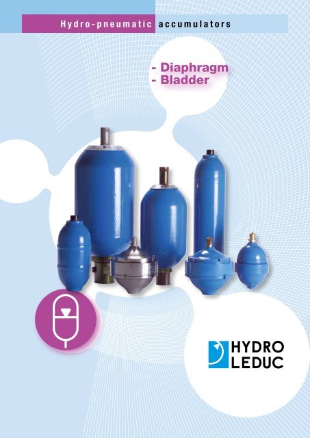
- Diaphragm - Bladder - Total Hydraulics BV
- Diaphragm - Bladder - Total Hydraulics BV
- Diaphragm - Bladder - Total Hydraulics BV

Create successful ePaper yourself
Turn your PDF publications into a flip-book with our unique Google optimized e-Paper software.
Contents■■How do accumulators work? .................... 1■■What are accumulators used for?.................. 2■■Order code. .................................. 3■■ACS-ACSL welded accumulators ................ 4-5■■AS-AF-AC spherical accumulators ............... 6-7■■A<strong>BV</strong>E bladder accumulators. ................... 8-9■■Clamps. ................................. 10-11■■Safety and shut-off blocks................... 12-13■■Charging equipment. .......................... 14■■Calculating the right accumulator and legislation..... 15■■Safety precautionsand maintenance recommendations............... 16■■The complete LEDUC product range.............. 17HYDRO LEDUCHead Office & FactoryBP 9F-54122 AZERAILLES (FRANCE)Tél. +33 (0)3 83 76 77 40Fax +33 (0)3 83 75 21 58
Hydro-pneumatichydropneumatiquesenergy, silence, comfort, service life…■■energy storageA hydro-pneumatic accumulator is a vessel which, in hydraulic circuits, iscapable of storing a large amount of energy in a small volume.■■a simple principleIf the very low compressibility of fluids makes it difficult to store their energyin small volumes, it does, however, enable them to transfer a significant force.Gas on the other hand is highly compressible, and can therefore store considerableamounts of energy in small volumes. The hydropneumatic accumulatormakes use of these two properties.How doaccumulatorswork?The hydropneumatic accumulator is atank divided into two chambers by a flexibleseparator. One chamber is for fluidunder pressure, the other for nitrogengas.1It is charged with nitrogento a pressure p o.When a fluid travels through the accumulator,and the pressure p 1of that fluidis greater than the pre-charge pressurepo of the accumulator, then the gascompresses to p 1, the separator changesshape, and the accumulator can take inthe corresponding volume of fluid.Any pressure drop in the hydraulic circuitcauses the accumulator to return fluid tothe circuit, until pressure reverts to theinitial p 0.
Hydro-pneumatic accumulatorsWhat are accumulators used for?■■Surge control■■Pulsation dampeningThe accumulator takes in the cinetic energy produced by a moving column offluid when the circuit is suddenly shut off (valve, solenoid etc.), or more generally,when there is a sudden change in circuit pressure.■■Thermal changeAdding a LEDUC accumulator to a hydraulic circuit smooths out any flowirregularities from the pumps. This leads to better operation of the system,protection of the components and thus increased service life, and reducednoise levels.Example: dosage pumps.■■Transfer of fluids2The increase in volume due to increased temperature will be absorbed by theLEDUC accumulator.■■Shock absorbing – suspensionLEDUC accumulators, in a shock absorbing function, reduce fatigue of hydraulicand mechanical components.Examples:--lifts,--forklift trucks,--agricultural machinery,--construction equipment, etc.■■Energy recovery and restitutionThe energy supplied by a given load can be absorbed by the accumulator andput back into a hydraulic cylinder to produce a mechanical movement.Example: closing railcar hopper doors.■■Leak compensationThe LEDUC accumulator makes it possible to transfer hydraulic pressurebetween two incompatible fluids, via the diaphragm which separates the twofluids.Examples:--transfer between hydraulic fluid and sea water,--test bench, etc.■■Energy storageIn a circuit under pressure, the LEDUC accumulators mean a reserve of fluidmay be kept permanently available. Thus a large amount of energy, accumulatedby a low power system during periods of low or no usage, can be usedin a very short time and within one cycle.Examples:--automatic machines,--braking or declutching of vehicles or construction equipment,--emergency completion of working cycle in case of failure of main powersource.A leak in a hydraulic circuit can lead to pressure drop. The LEDUC accumulatorcompensates the drop in volume and thus maintains circuit pressurevirtually constant.
Hydro-pneumatic accumulatorsOrder codeAS 0.7 060782 P E/1 310367 D 100OFFICIAL APPROVALS : unnecessaryD : CE approvalprotective treatment (for AS, AC, AF)S : without protective treatmentP : ARCOR ® anti-corrosion treatmentcharging valves and screws(see page 14)CAPACITY OF ACCUMULATOR (in litres),and reference codeaccumulator typeACS-ACSL : welded cylindricalAS : spherical modelAF : low temperature, high pressure,spherical modelAC : cylindricalA<strong>BV</strong>E : bladder typeTYPE OF DIAPHRAGME/1 : NBR (nitrile)E/2 : NBR (nitrile) stainlesssteel insertE/3 : ECO (epichlorydrine)E/4 : EPM (epr)E/5 : FKM (viton ® )PRE-CHARGE PRESSURE(bar)3■■Main characteristics of hydropneumatic accumulators according to technologyMain characteristics of accumulatorVolumetric ratio (capacity to store a volume)<strong>Diaphragm</strong> accumulatorRatio limited to 4 in dynamic6 for slow movement and 8 in staticType of accumulatorRatio limited to 4<strong>Bladder</strong> accumulatorMounting positionGas loss (osmosis)Loss is proportional to sealing surfaceVertical position preferred for all cases where length/diameter ratio > 4.Little to mediumVertical positionMediumSpeed of restitution Very quick QuickCapacity for total discharge Yes Only in particulaar conditionsFlow control No NoControl of the presence of fluid No or unreliable No or unreliableUse at high temperature (+120°C) Medium ReducedUse at low temperature (-30°C) Medium ReducedUse with special fluids Limited LimitedService life Good Good
Hydro-pneumatic accumulatorswelded cylindricalACS330 barACSL210 barMaximum pressure ................. 330 barExtreme operating temperatures:--standard version ..........– 20°C to + 120°C--low temperature version ....– 40°C to + 120°CMaximum pressure ................. 210 barExtreme operating temperatures:--standard version ..........– 20°C to + 100°C--low temperature version ....– 40°C to + 100°C■■Technical description■■Deformation of the bladderThe ACS-ACSL type welded accumulators are made up of a shell in highresistance steel containing a fluid-gas separator. This separator is made ofnitrile for the standard ACS range, and of hydrogenated nitrile for low temperatureapplications. The separator is fitted with an anti-extrusion stud, thusallowing rapid and total discharge of the accumulator.p 0 V 0 p 1 V 1 p 2 V 24■■Advantages--Low temperature versions suitable for operation at temperatures down to– 40°C.--Interchangeable, given outer dimensions, with most accumulators available.--Completely modular from 0.7 to 4 litres. This design concept means easyaddition of intermediate models if required.--The bladder offers exceptionally good resistance to fatigue.--Rapid and total discharge possible due to the anti-extrusion stud actuallyfitted onto the bladder.■■Gas chargingTwo versions of the ACS-ACSL are available:--with a charging screw,--with a charging valve.■■Examples of applicationsEnergy strorageSuspension■■Filling gasNitrogen only.■■Operating fluids- Mineral-based hydraulic fluids.- Other fluids: please ask.■■Volumetric ratio (V 0–V 2)/V 0The recommended volumetric ratio of this type of accumulator is 0.75.For example: an ACS 4 accumulator can take in a maximum volume of0.75 V0 = 0.75 x 4 = 3 litres.■■AccessoriesSafety blocks, see pages 12 and 13.Fixation devices, see page 11.Adaptateurs, voir page 11.■■Order codesSee page 3.
Hydro-pneumatic accumulatorswelded cylindricalACS - ACSLA 46 200 (1)13.50DBACLeduc part n° A B C DACS 0,7 066695 M33 x 1.5 G1/2’’ 14 20ACS 0,7 066735 M26 x 1.5 M14 x 1.514(as per ISO 6149)For other oil side threads, please contact our CustomerService Department.(1) US version.(2) on request: P1620 valve.charging valvecharging screwbladder117 (ACS)111 (ACSL) B114.3 (ACS)108 (ACSL)(1) dimensions with VGL 4 fittedDimensions are given only as an indication.anti-extrusion stud* Other oil side threads can be offered on request.16ACSreferencenitrogencapacity V 0litresmaximumpressurebar CEweightkgAmmoil side threadx Bgas sideorificeACS0.7 066445 0.7 330 4 176 G3/8" vis065975 0.7 330 4 176 G3/8" valveP1620066035 0.7 330 4 176 G3/4" vis066130 0.7 330 4 176 G1/2" vis066255 0.7 330 4 176 G1/2" valveP1620065950 0.7 330 4 176 M16 x 1,5 vis065952 0.7 330 4 176 M18 x 1,5 vis066845 (1) 0.7 330 4 176 3/4-16UNF-2B(SAE8) (1) vis065947 (1) 0.7 330 4 176 3/4-16UNF-2B(SAE8) (1) valveSCHRADERACS1 065960 1.1 330 5,9 246 G3/4" vis065976 1.1 330 5,9 246 G3/4" valveP1620065964 1.1 330 5,9 246 M18 x 1,5 vis066855 (1) 1.1 330 5,9 246 3/4-16UNF-2B(SAE8) (1) vis065965 (1) 1.1 330 5,9 246 3/4-16UNF-2B(SAE8) (1) valveSCHRADERACS1,5 065940 1.5 330 7,8 315 G3/4" vis065977 1.5 330 7,8 315 G3/4" valveP1620066840 1.5 330 7,8 315 M18 x 1,5 vis065945 (1) 1.5 330 7,8 315 3/4-16UNF-2B(SAE8) (1) valveSCHRADER066865 (1) 1.5 330 7,8 315 3/4-16UNF-2B(SAE8) (1) visACS2 066705 2 330 9,9 393 G3/4" vis066675 2 330 9,9 393 G3/4" valveP1620ACS2,5 065910 2.5 330 11,5 464 G3/4" vis065978 2.5 330 11,5 464 G3/4" valveP1620066875 (1) 2.5 330 11,5 464 3/4-16UNF-2B(SAE8) (1) vis065915 (1) 2.5 330 11,5 464 3/4-16UNF-2B(SAE8) (1) valveSCHRADER066685 (1) 2.5 330 11,5 464 1"1/16-12UN-2B(SAE12) (1) valveSCHRADERACS4 065920 4 330 17,5 696 G3/4" vis065979 4 330 17,5 696 G3/4" valveP1620066885 (1) 4 330 17,5 696 3/4-16UNF-2B(SAE8) (1) vis065925 (1) 4 330 17,5 696 3/4-16UNF-2B(SAE8) (1) valveSCHRADER066690 (1) 4 330 17.5 696 1"1/16-12UN-2B(SAE12) (1) valveSCHRADERACSL* referencenitrogencapacity V 0litresmaximumpressurebar CEweightkgAmmoil side threadx Bgas sideorificeACSL0.7 068125 0.7 210 3 175 G1/2" vis (2)068275 0.7 210 3 175 3/4-16UNF-2B(SAE8) (1) vis (2)068385 0.7 210 3 175 M18x1.5 vis (2)068440 0.7 210 3 175 M18x1.5 ValveP1620ACSL1 068130 0.99 210 4.5 245 G3/4" vis (2)068160 0.99 210 4.5 245 G1/2" vis (2)068280 0.99 210 4.5 245 3/4-16UNF-2B(SAE8) (1) vis (2)068395 0.99 210 4.5 245 M18x1.5 vis (2)068445 0.99 210 4.5 245 M18x1.5 ValveP1620ACSL1.5 068135 1.5 210 5.9 315 G3/4" vis (2)068410 1.5 210 5.9 315 3/4-16UNF-2B(SAE8) (1) vis (2)068450 1.5 210 5.9 315 M18x1.5 ValveP1620ACSL2 068140 2 210 7.6 392 G3/4" vis (2)068525 2 210 7.6 392 3/4-16UNF-2B(SAE8) (1) vis (2)068455 2 210 7.6 392 M18x1.5 ValveP1620ACSL2.5 068145 2.5 210 8.9 463 G3/4" vis (2)068530 2.5 210 8.9 463 1"1/16-12UNF-2B(SAE12) (1) vis (2)068460 2.5 210 8.9 463 M18x1.5 ValveP1620ACSL4 068390 4 210 13.9 695 G3/4" vis (2)068535 4 210 13.9 695 1"1/16-12UNF-2B(SAE12) (1) vis (2)068465 4 210 13.9 695 M18x1.5 ValveP16205
Hydro-pneumatic accumulatorssphericalAF500 barAS400 barMaximum pressure ..................500 barExtreme operating temperatures. – 20°C to + 100°CMaximum pressure ..................400 barExtreme operating temperatures. – 20°C to + 100°C■■Technical description■■Filling gas6LEDUC spherical accumulators consist of two hemispherical shells whichare screwed together and which hold a diaphragm. This diaphragm has ametal stud which closes off the operation hole when the fluid is completelydischarged. There is therefore no danger of damage to the diaphragm.The gas side port is fitted with a charging valve allowing the pressure in theaccumulator to be checked or changed.Séparateur:- Série, Nitrile: de – 20°C to + 100°C- Spécial: de – 40°C to + 100°C en usage dynamique.■■AdvantagesThe diaphragm only changes position, the elastomer in fact works little.The LEDUC spherical accumulator owes most of its qualities to its diaphragmand metal pin:--excellent gas/fluid tightness.--possibility of total and rapid discharge.Can be adapted to suit a wide range of fluids.hanged.■■ProtectionAvailable on request for AF and AS versions: ARCOR® anti-corrosion treatment.■■Deformation of the diaphragmNitrogen only.■■Operating fluids--Mineral-based hydraulic fluids: standard diaphragm.--Corrosive or non-standard fluids: please consult our Customer ServiceDepartment.■■Volumetric ratio (V 0–V 2)/V 0The volumetric ratio of this type of accumulator is 0.75.For example: an AX 1 accumulator can take in a maximum volume of 0.75 V0= 0.75 x 1 = 0.75 litres.■■AccessoriesSafety blocks, see pages 12 and 13.Fixation devices, see page 11.Adaptateurs, voir page 11.■■Order codesSee page 3.pp 0 V 0 p 1 V 2 V 21■■Examples of applicationsPulsation dampeningTransfer
Hydro-pneumatic DimensionsaccumulatorssphericalAS-AF AC 00 0232 on flats200 (1)charging valvediaphragm12101036 CEAD112B FK G Hanti-extrusion studG1/4"36 on flats(1) dimensions with VGL 4 fittedDimensions are given only as an indication.41,80AFreferencenitrogencapacity V 0litresmaximumpressurebar CEweightkgdimensions (mm)A B x C D E x F x G x H KAF 00 50 060972 0.45 500 2.8 184 89 114 12 23 112.5 40 G3/8" 16AF 01 00 060110 1.1 500 5.5 197 112 163.5 50.5 50.5 163.5 40 M18 x 1.5 127ASréférencenitrogencapacity V 0litresmaximumpressurebar CEweightkgdimensions (mm)A B x C D E x F x G x H KAS 00 20 060932 0.19 400 1.2 150 69 84.5 9 20 83.5 29 G1/4" 12AS 00 50 060972 0.45 400 2.8 184 89 114 12 23 112.5 40 G3/8" 16AS 00 70 060782 0.65 250 3 197 89 119.5 9 24 118.5 30 G3/8" 13AS 01 00 060110 1.1 400 5.5 197 112 163.5 50.5 50.5 163.5 40 M18 x 1.5 12AS 02 50 060812 2.55 400 14 251 161 213.5 37 29 210 51 G3/4" 17AS 04 00 060121 4.1 400 22 298 202 251 44 40 247 105 M33 x 2 20AS 10 00 060141 10.19 400 53 391 268 339 52.5 52.5 333 105.1 M33 x 2 20AC 00 02 060955 0.017 400 0.640 see drawing above
Hydro-pneumatic accumulatorsbladderA<strong>BV</strong>EMaximum pressure ................. 330 barExtreme operating temperatures. – 20°C to + 80°C330 bar8■■Technical descriptionThe A<strong>BV</strong>E bottle type acccumulators consist of:--a forged steel body,--a bladder,--a charging valve,--an oil side orifice fitted with a poppet valve which prevents extrusion of thebladder, and an air bleed screw used during system start-up.■■Advantages<strong>Bladder</strong> accumulator, component parts are interchangeable with those ofmajor accumulators available.Dimensions allow for easy installation and also use in batteries.■■Filling gasNitrogen only.■■Operating fluidsMineral-based hydraulic fluids: standard bladder.Non-standard and/or corrosive fluids: please consult our Customer ServiceDepartment.■■Deformation of the bladder■■Example of applicationsEnergy storage■■Volumetric ratio (V 0–V 2)/V 0The volumetric ratio of this type of accumulator is 0.75.For example, an A<strong>BV</strong>E 4 accumulator can take in a maximum volume of0.75 V0 = 0.75 x 4 = 3 litres.■■AccessoriesSafety blocks, see pages 12 and 13.Fixation devices, see page 11.Adaptateurs, voir page 11.■■Order codesSee page 3.p 0 V 0 p 1 V 1p 2 V 2
Hydro-pneumatic accumulatorsbladderA<strong>BV</strong>E200 (1)charging valve65bladderA Cpoppet valveB D E Fbleed screw hexagonal, 19 on flatsair bleed screw on A<strong>BV</strong>E 10 to 50 litres919adaptor on flats 70 G(1) dimensions with VGL 4 fittedDimensions are given only as an indication.nitrogen maximumA<strong>BV</strong>E reference capacity V 0pressure weightdimensions (mm)litres bar CE kg A B x C x D x E x F x GA<strong>BV</strong>E 4 066850 3.7 350 14 420 65 169 75 53 G1"1/4 G3/4" or fullA<strong>BV</strong>E 10 066860 9.2 330 30 568 88 219 101 76 G 2" G3/4" - 1" or fullA<strong>BV</strong>E 20 066870 17.8 330 50 888 88 219 101 76 G 2" G3/4" - 1" or fullA<strong>BV</strong>E 32 066880 32 330 80 1380 88 219 101 76 G 2" G3/4" - 1" or fullA<strong>BV</strong>E 50 066890 48.5 330 100 1885 88 219 101 76 G 2" G3/4" - 1" or fullHYDRO LEDUC provides after sales service, supplies spare parts and can requalify your accumulators (retesting).
Hydro-pneumatic accumulatorsclampsFor large capacity accumulators it is recommended to use seats. The number of fixationclamps used should be determined depending on the size of the accumulator.■■Fixation clampstype ofaccumulatorclampreferencedimensions (mm)A B C D F H JBC9AS 00 50 / AF 00 50AS 00 70ACS / ACSL 0.7 / 1 /1.5 / 2 / 2.5 / 4254021 160 139 87 118.5 M8 x 90 72.56 31.5F D9035244013HJAtype ofaccumulatorclampreferencedimensions (mm)H h L L1 L2 IL230AS 04 00 254005 285.5 132 248 300 - 30AS 02 50 254006 248 113 212 254 - 30hA<strong>BV</strong>E10 / 20 / 32 /50254007 - 119 216 254 297 30AS 01 00 / AFL01 00254022 207 92.5 148 184 - 30 lL 1AX 01 00 / A<strong>BV</strong>E 49H1310type ofaccumulatorclampreferenceACS / ACSL 0659581273010B 115M8 length 5070
Accessoriesclamps■■fixation seatstype ofaccumulatorreferenceA<strong>BV</strong>E4 254012802 x B1725160210B108175type ofaccumulatorA<strong>BV</strong>E 10/ 20 / 32/ 40reference25400825100404 x B17200260B159235■■Adaptorstype of accumulator reference ouletAS 02 50 066451 G1/2"AS/AF - AS 00 70EC1063 G1/2EC1069 M18 x 1,5AS/AFEC1054G1/2"EC1056G3/8"EC1061G3/4"AS 04 00 - AS 10 00EC1058G3/8"EC1059G1/2"A<strong>BV</strong>E 4066305 G3/4"066307 blind066074 G3/4"A<strong>BV</strong>E 10/20/32/50066068 G1"066069 blind11
AccessoriesSafety and shut-off Blocks12■■DescriptionThese safety and shut-off blocks are designed to bring together in a singleblock the necessary safety organs required for the correct functionning ofhydraulic circuits incorporating accumulators.The basic block consists of:--Ball valve with quarter turn closure, allowing the accumulator to be isolatedfrom the circuit;--Needle valve ensuring the manual decompression of the circuit;--Pressure limiter (directly operated) set at the maximum operating pressureof the accumulator. This pressure limiter should never be used as the limiterto protect the hydraulic pump;--Manometer plug;--The E24 and E220 models are fitted with a 2 way, 2 position electro-valve,allowing decompression of the circuit by switching off the supply current;--The Q version is fitted with a one-way adjustable flow limiter. Mounted onthe main block, this limiter controls the accumulator outlet flow, whilst inletflow remains unrestricted.■■General technical characteristics--Nominal crossing diameter: 16 mm (BS 1 Block), 24 mm (BS 2 Block);--Maximum working pressure: 350 bar;--Temperature range: – 20°C to + 70°C;--Fluid: mineral based hydraulic oil (for other fluids please contact our CustomerService department);--Supply voltage of the decompression: valve 220 V AC / 50 Hz – 24 V;--Energy Input: AC: 50 VA; DC: 21 W;--Flow: see pressure loss graph;--Pressure limiter (nominal diameter): 6 mm (BS1), 10 mm (BS2);--Fitting of the BS2 Safety block, output side: welding-neck flange (CETOP400 bar standard).NB1: the pressure limiter (0-400) is pre-set at 330 bar, but may be set atother values on request.NB2: as standard, BS2 is fitted with a 2’’ port (accumulator fitting).NB3: all safety and shut-off blocks have an electrical interface designedaccording to CETOP 3 standard, covered by a sealing plate except for modelsE24 and E220. The other models can therefore be used with other supplyvoltages, in such cases the end-user should source and insert the necessarysolenoids him/herself.■■The safety and shut-off blocks are available in asimplified versionThey consist of pressure limiter (directly operated) set at the maximum operatingpressure of the accumulator. This pressure limiter should never be usedas the limiter to protect the hydraulic pump.■■General technical characteristics--Nominal crossing diameter: 16 mm;--Maximum working pressure: 350 bar;--Temperature range: – 20°C to + 70°C;--Fluid: mineral based hydraulic oil (for other fluids please contact our CustomerService department);--Pressure limiter (nominal diameter): 6 mm.■■Order codes for safety and shut-off blocksExample of codification:BS 1 E24 Q 330 BQSize--1 = 16--2 = 24Decompression control--M = manual--E24 = electric 24V CC--E220 = electric 220 V 50 HzPressure limiter--Q = with limiter--Nothing written = without limiterSetting the pressure limiter--0 to 400 bar depending on type of accumulatorOptional fitting for BS1--A = ACS - ACSL 1 to 4 (3/4") BS1 without limiter--B = A<strong>BV</strong>E 4 (1"1/4) BS1 without limiter--C = A<strong>BV</strong>E 10 to A<strong>BV</strong>E 50 (2") BS1 without limiter--Q = for BS1 with limiterNota: order codes for the simplified safety and shut-off blocks: BS + pressuresetting of the pressure limiterExample 1: a size 16 block, with control of electrical decompression 24VDS, with pressure limiter set at 330 bar, and fitting flange 1’’1/4:BS1E24Q330BQ.Example 2: a size 24 block, with manual decompression control, pressurelimiter set at 250 bar: BS2M250.Example 3: (simplified safety and shut-off block): a simplified safety and shutoffblock with pressure limiter set at 330 bar: BS330.■■Graph of pressure drop as a function of flowPressure loss (bar)654321BS1 and BS2 Pressure lossOil viscosity: 30 cStBS1BS2100 200 300 400 500 600Flow (l/min)
TPMAAccessoriesSafety and shut-off BlocksTPBS22.56633.5x G3/4"89x 33depth 2.5x 19depth 1.551T G1/4"T80 A35BP72M45 35 CTAPTPSafety blocks: Different versions available: please seeorder code system on page 12.Thread gas cyl. x A 3/4" 1"1/4 2"B 16 20 24TPC 30 30 35AMBS1 MAMBS1 MQAM AAAT ATPMMTC40ATC47P8440TP16884M13284TPx 3/4’’ gas cyl8477 72Spot-facing x 36.3 depth 1.2TPx 3/4’’ gas cylTA161P77 72Spot-facing x 36.3 depth 1.2BS1 EAMAMBS1 EQAAMAMA ATPTM APMA168C40TPT47PA84TP13MA84MTPA77 72PTPC4084132x 3/4’’ gas cyl84132 for CA127 for CCTSpot-facing x 36.3 depth 1.2x 3/4’’ gas cylT161P132 for CA127 for TCCSpot-facing x 36.3 depth 1.2A77 72PTPMBS2 MAMABS2 MQMAATx 2" gas cyl.TPMM226221151116116509616451,666,74 threads T holes M 12 depth P 20A31,551,6Connection* on usage sideStandard version:CETOP flange 1"1/4 400 bar51.6 x 51.6 between axisMTT221219.5116APP11650T33P96TPTBS2 EAMAMBS2 EQAAMAMAx 2" gas cyl.TPTMP226MA22115111611650T132 for CA127 for CC96P164MTTAPPT221219.5116TPA116PM50T33132 for TCA127 for CC96APTPP* This interface is the same on all the BS2 blocks.
AccessoriesCharging equipment■■Charging valvesThe P 1620 universal valve exists in two versions:--P 1620.: standard valve, M 16 x 200 threads per inch.--PX 1620.: stainless steel valve, M 16 x 200 threads per inch.chargingvalveP 1620referenceScrew 066542connectionon gas side (A)accumulatorRemark310367 G 1/4 ACS - AS Standard310379 M10x1.50 A<strong>BV</strong>E Standard310372 G 1/4 AS - AF - AX INOXV10N 1/2 20 UNF ACS - AS - A<strong>BV</strong>E old valve V10NM8X1.25 withBS130331 ringchargingdeviceVGL 4AdaptorM 28 x 1.50M 16 x 2.00ACS Standard VGL 4 withoutSchrader 067210 G1/4 ACS - AS VGL 4M 28 x 1.508V1Bx 20P 1620réf. B C sur plats310367 36 19310379 38 17310372 36 19V10N 36 19AC9,3 3014■■Charging kitReference: CGLU 4F/D* 066650CGLU 4F: includes hose adapter for use on French nitrogen bottles.*CGLU 4D: German (European) version, available on request, includes hoseadapter for use on German nitrogen bottles.The charging kit comprises:- VGL 4 universal pressure charging and gauging device (M28 x 1.50 outlet)--two pressure gauge kits: 0 to 25 bar and 0 to 250 bar, additional manometerson request (0-100; 0-400);--adapters for connection to charging valves (M16x200 - 5/8’’ - G3/4’’ - 7/8’’- 8V1);--2.50 m-long hose, for connection to a source of nitrogen, standard versionfor pressures up to 400 bar. For higher pressures, please contact our TechnicalSales Department;--6 mm A/F Allen wrench;--spare seal kit.■■Charging and gauging deviceReference: VGL 4 066660DescriptionThe VGL 4 charging and gauging device is the essential instrument to checknitrogen filling pressure and to reduce nitrogen pre-charge pressure of accumulators,up to maximum working pressure of 400 bar.Technical characteristicsMaximum pressure: 400 barAccumulator connection: M 16x200 - 5/8’’ 18UNF - G3/4’’ - M28 x 1.50(7/8’’ 14 UNF - 8 V1 with CGLU 4)Pressure gauges: 63 mm diameter (glycerin-bath type) with G1/4’’ Cyl. rearoutlet, fitted with a direct-connection to a rapid connector. Scale 0 to 400 bar(or other on request) with accuracy of 1.6.6 on flatsM 28 x 1.50
Hydro-pneumatic accumulatorsCalculating and legislationDetermining the right LEDUCaccumulator for your application .Free of charge, available on request, a USB stick withsoftware to assist in calculations to determine the rightaccumulator for each application.15■■LegislationHydraulic accumulators are gas pressure vessels.The manufacture of such products must conform to CE directive 97/23/CE.Local regulations and legislation must be strictly respected regarding the useof accumulators.European legislation 97/23/CELEDUC accumulators of less than 1 litre capacity are supplied with a manufacturer’scertificate. They cannot be stamped CE, but conform to the CEdirective.LEDUC accumulators of 1 litre capacity or more are supplied with a CE certificateof conformity. They bear the CE stamp and the reference of the officialorganisation certifying their conformity.Use of these accumulators in France is governed by decree dated 15 March2000 (Official Bulletin n°96).Useful addresses:--French legislation and application of directive 97/23/CE:http://www.adminet.com/jo--European legislation: http://europa.eu.intIndependent approved organisations: ASAP, APAVE, TÜV, VERITAS...
Hydro-pneumatic accumulatorsPrecautions and maintenance16■■Installing and connecting your accumulatorThe accumulator must be installed in an easily accessible place and should befixed in place using robust collars: see page 14. It is important that the markingsengraved on the accumulators remain visible.Hydraulic connections: the dimensions of the connection ports are specifiedon the preceeding pages, for each accumulator.Pipes must not put any strains on the accumulator.The accumulator must be connected to a hydraulic circuit using only mineralbasedhydraulic oil or equivalent. For other fluids, please consult our CustomerService Department.Any operation to modify the external appearance of the accumulator (welding,grinding, machining etc.) is strictly forbidden.The accumulator should be suitably protected (paint or other protection)against external corrosion.The circuit must include an isolation valve to isolate the accumulator, and alsoa means of checking that the hydraulic pressure never exceeds the maximumpressure engraved on the accumulator: see pages 12 and 13 regarding safetyand shut-off blocks.The accumulator must be connected to a pressure limiter set at a pressurenot greater than the accumulator’s maximum service pressure capability.■■ChargingThe pre-charge pressure must be less than the operating pressure engravedon the accumulator shell.It is important to ensure the accessibility for a charging and gauging device(see page 14, charging equipment).Pre-charge pressure must be checked before operation (see paragraph on“accumulator recommendations” below)Use only nitrogen (N2, minimum quality I).If the nitrogen pressure of the installation connected - for the purposes ofcharging - to the accumulator is greater than the maximum acceptable pressureengraved on the accumulator, it is essential to install a pressure regulatorbetween the bottle and the hose.The influence of temperature on charging pressure should be taken intoconsideration.A reference table is available from HYDRO LEDUC on request.■■Start-upCheck that the hydraulic installation is able to withstand the maximum pressureengraved on the accumulator.After the hydraulic connection to the circuit, the pipework must be bled carefully.Use the safety and shut-off blocks described on pages 12 and 13.■■UseThe maximum hydraulic pressure must never exceed the operating pressure(PS) engraved on the accumulator shell: check using appropriate equipment(see page 14, chargind and gauging kit).The volumetric ratio (V 0–V 2)/V 0must not be exceeded, see the technicaldescription for each accumulator.Bleed the pipework of any air.The accumulator must operate within the prescribed extreme operatingtemperatures.■■Maintenance and controlBefore intervening in any circuit which has a gas filled pressure vessel, thepressure must be discharged from the circuit.Check the nitrogen pressure regularly, see the “accumulator instructions”below, and page 14 regarding charging equipement.Check regularly that there is no external corrosion.■■Recommendations concerning accumulatorsExtract from instructions included with each accumulator delivered:How our accumulators are delivered--Either: pre-charged to a storage pressure of around 5 bar. In this case,before use charge to required nitrogen pressure using the charging assembly(VGL 4). Check the P 1620 valve or charging screw is airtight. Putthe P 1620 back in place.--Or : pre-charged with nitrogen to the pressure corresponding to thatcalculated for the working conditions of the application. In this case checkthat the pre-charge pressure marked on the label on the accumulator correspondsto the necessary calculated pressure.■■Frequency of checksThe pre-charge pressure p 0marked on the accumulator must be checkedeach time the accumulator is assembled in a system, and after every service.At least one check must be made during the first week of service.The pre-charge pressure of the accumulator should also be checked at leastonce during the first week of service. Provided no gas leak is observed afurther check should be made around 4 months later. Provided at this checkthere is still no gas leak, an annual check thereafter may be considered sufficient.■■ChecksEnsure before any checks that the accumulator has been isolated from thecircuit and decompressed on the oil side.Use the LEDUC VGL 4 gauging device.NOTE: use a manometer with a measuring range compatible with the nitrogenpressure you want to check.Welding robot for accumulators
other autres product fabrications lineshydraulic motorsXPFixed displacementbent-axis pistons motors.Models from 12 to 126 cc.Available both in ISOand SAE versions.TXVPAPACPADpiston pumpsfor trucksHYDRO LEDUC offers 3 types of piston pumps perfectlysuited to all truck and PTO-mount applications.Fixed and variable displacement from 12 to 150 cc.micro-hydraulicsmobile andindustrial pumpsFixed displacement pumps, the W series, and variabledisplacement pumps, the DELTA series. High pressurecapabilities within minimal size.W series: fl anges to ISO 3019/2, shafts to DIN 5480.DELTA series: SAE shafts and fl anges.This is a fi eld of exceptionalHYDRO LEDUC know-how:• axial and radial piston pumps,of fi xed and variable displacement,• axial piston micro-hydraulic motors,• micro-hydraulic units incorporatingpump, electric motors, valving, controls,etc.To users of hydraulic components which have tobe housed in extremely small spaces,HYDRO LEDUC offers complete, original and reliablesolutions for even the most diffi cult environments.we are passionateabout hydraulics…hydro-pneumaticaccumulators<strong>Bladder</strong>, diaphragm accumulators.Spherical and cylindrical accumulators.Volume capacities from 20 cc to 50 liters.Pressures up to 500 bar.Accessories for use with hydraulic accumulators.A dedicated R&D team means HYDRO LEDUC is able to adapt or createproducts to meet specifi c customer requirements. Working in closecooperation with the decision-making teams of its customers, HYDRO LEDUC optimizesproposals based on the specifi cations submitted.
a passionfor hydraulicsHYDRO LEDUCHead Office & FactoryBP 9 - F-54122 AZERAILLES (FRANCE)Tél. +33 (0)3 83 76 77 40Fax +33 (0)3 83 75 21 58HYDRO LEDUC GmbHHaselwander Str. 5D-77746 SCHUTTERWALD (DEUTSCHLAND)Tel. +49 (0) 781-9482590Fax +49 (0) 781-9482592HYDRO LEDUC N.A., Inc.19416 Park Row - Suite 170HOUSTON, TEXAS 77084 (USA)Tel. +1 281 679 9654Fax +1 832 321 3553Complete catalogues available at:www.hydroleduc.comHYDRO LEDUCSAS with capital of 4 065 000 eurosSiret 319 027 421 00019RC Nancy B 319 027 421mail@hydroleduc.comThe information is given as rough guide. Not contractual document. Cancels and replaces previous version.Editech.com12/07/2012