Fire-resistant cable installation - Above ... - OBO Bettermann
Fire-resistant cable installation - Above ... - OBO Bettermann
Fire-resistant cable installation - Above ... - OBO Bettermann

Create successful ePaper yourself
Turn your PDF publications into a flip-book with our unique Google optimized e-Paper software.
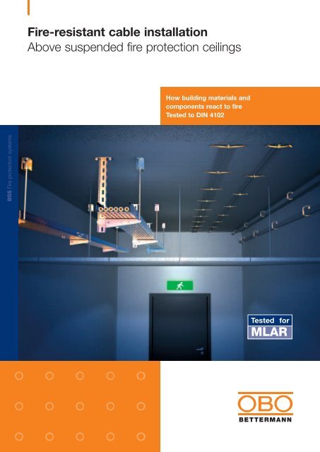
<strong>Fire</strong>-<strong>resistant</strong> <strong>cable</strong> <strong>installation</strong><strong>Above</strong> suspended fire protection ceilingsHow building materials andcomponents react to fireTested to DIN 4102BSS <strong>Fire</strong> protection systemsTested forMLAR
Safe as houses<strong>OBO</strong> fire protection in false ceilings2 BSS
We have thought of everything – because there can be no weak links in the fire protection chain<strong>OBO</strong> has been producing fire protection systems for electrical <strong>installation</strong>s for many years. In accordance with the requirements ofstatutory regulations and legal provisions, all systems have been tested and approved to appli<strong>cable</strong> fire protection standards. Assafety is becoming an ever more prevalent issue, legislators are continuing the now familiar trend of setting out more and morespecifications for fire protection. The validity of these specifications extends to electrical <strong>installation</strong>s, and proof of such compliancemust be provided. Options for fire-<strong>resistant</strong> <strong>cable</strong> <strong>installation</strong> above suspended fire protection ceilings do of course also fallwithin the scope of such specifications.MLAR (guidelines for the fire protectionrequirements to be met by<strong>cable</strong> systems in Germany)The latest version of MLAR, publishedin March 2000, has been adopted incurrently enforceable construction lawin all German states.This has led to the introduction of anumber of important changes affectingelectrical <strong>installation</strong>s. With fewexceptions, open <strong>cable</strong> <strong>installation</strong>smay no longer be used in escape routesand emergency exits.Options for <strong>cable</strong> <strong>installation</strong> in escaperoutes and emergency exitsIn escape routes and emergency exits,electrical lines must be installed as follows:· Individually, fully embedded in plasteror in wall channels covered with a layerof plaster· In fire protection ducts, e.g. <strong>OBO</strong> BSK· <strong>Above</strong> suspended ceilingsRequirements to be met wheninstalling <strong>cable</strong>s in false ceilingsSuspended fire protection ceilings, testedand approved for fire loads fromabove, ensure that false ceilings are protectedagainst fire. In the event of the<strong>cable</strong>s installed catching fire, escaperoutes and emergency exits can still beused.However, it must be ensured that theceiling does not become subject toadditional mechanical load in the eventof fire. In the event of fire in a false ceiling,the latter must not come down orbow. This requirement is also appli<strong>cable</strong>to all other <strong>installation</strong>s, e.g. sanitary services,ventilation.Options for <strong>cable</strong> <strong>installation</strong> infalse ceilingsIn principle, there are two methods forinstalling <strong>cable</strong>s in false ceilings:· Function maintenance <strong>installation</strong> systemsto DIN 4102 Part 12· Installation systems tested and approvedspecifically for this type of applicationIf function maintenance systems are usedin conjunction with standard insulated<strong>cable</strong>s and lines, all <strong>installation</strong> parametersmust remain unaffected, in order toavoid invalidating test certificates provingcompliance. However, these <strong>installation</strong>parameters are not entirely satisfactoryfor <strong>cable</strong> <strong>installation</strong> in practice.Tested and approved <strong>installation</strong>options by <strong>OBO</strong> <strong>Bettermann</strong><strong>OBO</strong> <strong>Bettermann</strong> has carried out firetesting based on the requirements ofDIN 4102 in order to make possiblepractical options for <strong>cable</strong> <strong>installation</strong> infalse ceilings.The following solutions have been testedand approved:· Wall-mounting and ceiling-mounting<strong>cable</strong> support systems· Type 2031 M/15 and type 2031 M/30grouped support for wall and ceilingmounting· Type 2023 M and type 2034 M metalpressure clips for ceiling mountingBSS3
Stable and strong<strong>OBO</strong> <strong>cable</strong> support systems<strong>OBO</strong> <strong>cable</strong> support systems for false ceilingsIn Germany, there is no single test standard for the use of <strong>cable</strong>support systems above suspended fire protection ceilings.<strong>OBO</strong>’s <strong>installation</strong> systems were therefore tested based on therequirements of DIN 4102 under a fire load of 30 minutes’duration.The following requirements were tested:· Stability of the <strong>installation</strong> system· Distortion of the <strong>installation</strong> systemSystem descriptionThe tested and approved <strong>installation</strong> system comprises <strong>cable</strong>trays with a rail height of 60 mm and widths up to a maximumof 600 mm. Cable trays are connected by making a specialscrewed joint. The system can be mounted on a suspensionsystem or on a wall.The suspension system comprises a support to which a bracketis connected. In the event of wall mounting, this bracket isfixed directly to the wall.In order to prevent the bracket tip bending, it must be fittedwith a threaded rod protector (vertical to the ceiling). For thispurpose, a suitable connection angle is screwed into thebracket tip.The threaded rod can be fixed to the ceiling with a fire protectionbracket or directly in a female anchor.4 BSS
Cable loadsEvery 100 mm of tray width can support a <strong>cable</strong> load of up to15 kg/m. This value applies for both types of <strong>cable</strong> tray used.This results in the following maximum possible <strong>cable</strong> occupationsunder a fire load of 30 minutes’ duration, determined bythe various tray widths.DistortionsAs the <strong>cable</strong> load placed on the <strong>cable</strong> trays in the event of fireleads to distortion, these distortions must be taken into accountwhen specifying the distances between the <strong>cable</strong> trays andthe suspended ceiling.This results in the following <strong>cable</strong> tray distortion rates at maximumpossible <strong>cable</strong> occupation, determined by the varioustray widths.Tray widthCable occupationTray type Tray width Distortion200 mm Max. 30 kg/m300 mm Max. 45 kg/m400 mm Max. 60 kg/m500 mm Max. 75 kg/m600 mm Max. 90 kg/mMKS 620 200 mm 80 mmMKS 630 300 mm 125 mmMKS 640 400 mm 170 mmSystem limitsTray type Tray width DistortionSpan:Width of <strong>cable</strong> trays:Type MKS 6No. of layers:Type SKS 6Max. 1.5 m200 mm300 mm400 mm200 mm300 mm400 mm500 mm600 mm1 layerSKS 620 200 mm 065 mmSKS 630 300 mm 095 mmSKS 640 400 mm 130 mmSKS 650 500 mm 160 mmSKS 660 600 mm 190 mmBSS5
Safety in detailEquipment requiredEquipment required per suspension point:Component Number TypeSupport 1 US 5 K...<strong>Fire</strong> protection bolt anchor 2 FAZ 12/10Bracket 1 AW 30F/...Spacer 1 DSK 45Hexagon head bolt (complete) 1 12530/90Cable tray 1 MKS 6.../ SKS 6...Connector (complete) 2 RWVL 60Joint plate (complete) 1 SSLB...Truss-head bolt (complete) 5 FRS B 6 x 12Truss-head bolt (complete) 1 FRS B 6 x 20Threaded rod 1 2078 M12Ceiling mounting with fire protection bracket<strong>Fire</strong> protection bracket 1 BSB<strong>Fire</strong> protection anchor 1 FAZ 12/10Hexagon nut 4 934 M12Washer 2 966/12Equipment required per suspension point:Component Number TypeBracket 1 AW 30F/...<strong>Fire</strong> protection anchor or 1 FAZ 12/10 or<strong>Fire</strong> protection anchor bolt 1 MMS 10x80Cable tray 1 MKS 6.../ SKS 6...Connector (complete) 2 RWVL 60Joint plate (complete) 1 SSLB...Truss-head bolt (complete) 5 FRS B 6 x 12Truss-head bolt (complete) 1 FRS B 6 x 20Threaded rod 1 2078 M12Ceiling mounting with fire protection bracket<strong>Fire</strong> protection bracket 1 BSB<strong>Fire</strong> protection anchor 1 FAZ 12/10Hexagon nut 4 934 M12Washer 2 966/12Ceiling mounting with female anchor<strong>Fire</strong> protection anchor 1 FZEA 14 x 40Hexagon nut 2 934 M12Washer 1 966/12Ceiling mounting with female anchor<strong>Fire</strong> protection anchor 1 FZEA 14 x 40Hexagon nut 2 934 M12Washer 1 966/126 BSS
Ordering dataCable support systemsAngle connectorType Side height Pack Weight Art. no.mm qty kg/100RWVL 60 60 10 17.500 6067 11 5SSLB joint plateType Width Pack Weight Art. no.mm qty kg/100SSLB 200 200 20 17.900 7070 21 3SSLB 300 300 20 27.600 7070 21 7SSLB 400 400 20 37.300 7070 22 1SSLB 500 500 20 46.900 7070 22 5SSLB 600 600 20 56.600 7070 23 3U supportType Length Pack Weight Art. no.mm qty kg/100US 5 K/020 200 1 100.000 6341 52 7US 5 K/030 300 1 125.000 6341 53 5US 5 K/040 400 1 150.000 6341 54 3US 5 K/050 500 1 175.000 6341 55 1US 5 K/060 600 1 200.000 6341 57 8US 5 K/070 700 1 225.000 6341 58 6US 5 K/080 800 1 255v.000 6341 59 4US 5 K/090 900 1 280.000 6341 60 8US 5 K/100 1000 1 300.000 6341 61 6US 5 K/110 1100 1 330.000 6341 62 4US 5 K/120 1200 1 360.000 6341 63 2BracketType Length Pack Weight Art. no.mm qty kg/100AW 30F/21 210 20 042.000 6417 02 7AW 30F/31 310 20 063.000 6417 04 3AW 30F/41 410 20 093.000 6417 07 8AW 30F/51 510 10 137.000 6417 09 4AW 30F/61 610 10 167.000 6417 11 6Truss-head boltType Dimensions Pack Weight Art. no.mm qty kg/100FRS B 6 x 12 M6 x 12 100 0.990 6406 12 2FRS B 6 x 20 M6 x 20 100 1.137 6406 20 3Threaded rodType Thread Pack Weight Art. no.qty kg/1002078 M12 M12 1000 1.000 3141 30 6Length: 1000 mmHexagon nutType Thread Pack Weight Art. no.qty kg/100DIN 934 M12 100 1.730 3400 12 3WasherType Thread Pack Weight Art. no.qty kg/100966 M12 100 0.627 3402 12 6SpacerType Pack Weight Art. no.qty kg/100DSK 45 25 19.000 6416 50 0Hexagon head boltType Dim. Pack Weight Art. no.mm qty kg/100SKS 10x90 M 10 x 90 20 8.000 6418 25 2<strong>Fire</strong> protection bracketType Pack Weight Art. no.qty kg/100BSB 1 41.000 6418 19 8MKS <strong>cable</strong> trayType Width Weight Art. no.mm kg/100MKS 620 200 225.600 6055 20 6MKS 630 300 281.000 6055 30 3MKS 640 400 348.300 6055 40 0Stock length 3000 mm, sheet thickness 1 mmSKS <strong>cable</strong> trayType Width Weight Art. no.mm kg/100SKS 620 200 356.800 6056 20 2SKS 630 300 421.500 6056 29 6SKS 640 400 522.400 6056 40 7SKS 650 500 650.300 6056 50 4SKS 660 600 726.600 6056 60 1Stock length 3000 mm, sheet thickness 1.5 mmBolt anchorType Thread Pack Weight Art. no.qty kg/100FAZ 12/10 M12 20 10.400 3498 65 4Approval no. ETA-00-0001Drive-in tie boltType Thread Pack Weight Art. no.qty kg/100FZEA 14 x 40 M12 50 2.750 3492 09 5General purpose masonry drillType Drill Ø Pack Weight Art. no.mm qty kg/100FZUB 14 x 40 14 1 12.500 3492 39 7Drive-in mandrelType Pack Weight Art. no.qty kg/100FZED 14 x 40 10 25.000 3492 69 9<strong>Fire</strong> protection anchor boltType Dimensions Pack Weight Art. no.mm qty kg/100MMS 10 x 80 10 x 80 50 3.800 3498 12 3Approval no. Z-21.1-1549BSS7
Strong and durable<strong>OBO</strong> grouped supportsThe mechanical stability of <strong>OBO</strong> GRIP type 2031 M/15 and type2031 M/30 grouped supports was tested in accordance withDIN 4102 under a fire load of 90 minutes’ duration.Description<strong>OBO</strong> GRIP grouped supports have been used in <strong>cable</strong> <strong>installation</strong>for many years. In this respect, the use of the metal supportsfor function maintenance is a specific application in termsof fire protection. Proof of the stability of <strong>OBO</strong> grouped supportsmade from sheet steel for ceiling and wall mounting can nowalso be provided.For <strong>cable</strong> occupation, the grouped supports can be openedeasily at the front, with no need for additional tools. Once the<strong>cable</strong>s have been installed, the grouped supports can be closedjust as easily, without having to use a tool. The design of the fasteningand the weight of the installed <strong>cable</strong>s prevent unintentionalopening following <strong>installation</strong>.Load-bearing capacityFor fire testing in accordance with DIN 4102, proof of stabilitywas calculated for the following load-bearing capacities undera fire load of 90 minutes' duration.The values are relevant for wall and ceiling mounting respectively.TypeLoad-bearing capacity2031 M/15 Max. 2.0 kg2031 M/30 Max. 3.5 kgCable occupationThe possible <strong>cable</strong> occupation based on load-bearing capacityis significantly higher than the theoretical <strong>cable</strong> occupation.This is based on occupation with NYM lines 3 x 1.5 mm 2 or on<strong>cable</strong>s and lines 9 mm in diameter. Type 2031 M/15 and type2031 M/30 grouped supports can hold 15 and 30 of these linesrespectively.Based on <strong>installation</strong> clearance, the following <strong>cable</strong> weights arepossible.Installation Possible <strong>cable</strong> weightclearanceType 2031 M/15 Type 2031 M/3040 cm 5.00 kg/m 875 kg/m50 cm 4.00 kg/m 7.00 kg/m60 cm 3.33 kg/m 5.83 kg/m70 cm 2.86 kg/m 5.00 kg/m80 cm 2.50 kg/m 4.38 kg/m8 BSS
Ordering dataGrouped supportThe table below lists approximate dimensions and weights of anumber of <strong>cable</strong>s and lines for calculating <strong>cable</strong> weight.Grip MType Pack Weight Art. no.qty kg/1002031 M/15 50 3.700 2207 02 8Cable type Cable ø WeightNYM 3 x 1.5 mm 2 8.2 mm 0.135 kg/mNYM 5 x 1.5 mm 2 9.5 mm 0.190 kg/mJ-Y(St)Y 2 x 2 x 0.6 mm 2 5.0 mm 0.030 kg/mJ-Y(St)Y 10 x 2 x 0.6 mm 2 9.0 mm 0.110 kg/mMountingThe stability of the grouped support under fire load can only beassured if the mounting under the ceiling or on the wall is ableto deflect the loads reliably. Anchors tested and approved inaccordance with fire protection regulations should therefore beused to mount grouped supports. A variety of products are availablefor the different types of mounting surface.Concrete surface:· <strong>OBO</strong> fire protection anchor type FNA 6 x 30/5 or type FNA 6x 30 M6/5· <strong>OBO</strong> fire protection anchor bolt type MMS 6 x 50Stone-type brickworkSolid sand-lime brick, perforated sand-lime brick orsolid brick:· <strong>OBO</strong> fire protection anchor bolt type MMS 6 x 50Grip MType Pack Weight Art. no.qty kg/1002031 M/30 25 6.200 2207 03 6<strong>Fire</strong> protection anchorType Thread Pack Weight Art. no.qty kg/100FNA 6 x 30 M6/5M6 100 1.400 3498 42 5Drilled hole depth: 45 mm, drill ø: 6 mmApproval no. Z-21.1-606<strong>Fire</strong> protection anchorType Head ø Pack Weight Art. no.mm qty kg/100FNA 6 x 30/5 15 100 1.120 3498 46 8Drilled hole depth: 45 mm, drill ø: 6 mmApproval no. Z-21.1-606<strong>Fire</strong> protection anchor boltType Dimensions Pack Weight Art. no.mm qty kg/100MMS 6 x 50 6 x 50 100 0.960 3498 10 7Drilled diameter: 5 mmBSS9
New and nifty<strong>OBO</strong> metal pressure clipsFor <strong>OBO</strong> “type 2033 M” and “type 2034 M” metal pressure clips,testing in accordance with DIN 4102 proved mechanical stabilityunder a fire load of 30 minutes’ duration. The test was carriedout for ceiling mounting only.DescriptionThe new spring-loaded stainless steel clips are a logical additionto the range of plastic pressure clips. They combine simpleoptions for <strong>cable</strong> <strong>installation</strong> under ceilings with adherence torequirements for stability in the event of fire.Metal pressure clips are suitable for the <strong>installation</strong> of <strong>cable</strong>s andlines with a maximum diameter of 10 mm. Cables can be installedfrom both sides (simply slide them underneath the lip of the clip).A tool is not required to actually install the <strong>cable</strong>s. The edges ofthe clips are set at an angle in order to avoid damaging the <strong>cable</strong>s.Pressure clips are available in two different sizes. These sizessupport the <strong>installation</strong> of the following numbers of NYM 3 x1.5 mm 2 <strong>cable</strong>s, for example.· Type 2033 M: 16 <strong>cable</strong>s (2 x 8)· Type 2034 M: 10 <strong>cable</strong>s (2 x 5)Load-bearing capacity<strong>Fire</strong> testing under a fire load of 30 minutes’ duration provedmechanical stability for ceiling mounting.The pressure clips may therefore be used subject to observanceof the following <strong>installation</strong> parameters:Requirement Type 2033 M Type 2034 MCable occupation 2 x max. 8 <strong>cable</strong>s 2 x max. 5 <strong>cable</strong>sCable diameter Max. 10 mm Max. 10 mmWeight ofindividual <strong>cable</strong> Max. 0.230 kg/m Max. 0.230 kg/mFixing spacing Max. 50 cm Max. 60 cm10 BSS
Ordering dataPressure clipCable occupationIn order to provide as clear an impression as possible of possible<strong>cable</strong> occupation, the following table lists examples of theapproximate dimensions and weights of a number of <strong>cable</strong>s andlines.Cable type Cable ø WeightNYM 3 x 1.5 mm 2 8.2 mm 0.135 kg/mNYM 5 x 1.5 mm 2 9.5 mm 0.190 kg/mJ-Y(St)Y 2 x 2 x 0.6 mm 2 5.0 mm 0.030 kg/mJ-Y(St)Y 10 x 2 x 0.6 mm 2 9.0 mm 0.110 kg/mPressure clipType Pack Weight Art. no.qty kg/1002033 M 25 2.310 2204 00 02034 M 50 1.860 2204 01 0<strong>Fire</strong> protection anchor boltType Dimensions Pack Weight Art. no.mm qty kg/100MMS 6 x 50 6 x 50 100 0.960 3498 10 7Drilled hole diameter: 5 mmMountingIn order to deflect the applied load, anchors tested and approvedin accordance with fire protection regulations should be used tomount pressure clips.The <strong>OBO</strong> type MMS 6 x 50 fire protection anchor bolt, which canbe mounted without an additional anchor, is both suitable andhas been approved for mounting underneath concrete ceilings.Mounting of pressure clips without anchors using <strong>OBO</strong>’sMMS anchor boltDrill hole, fix pressure clip in placeScrew in anchor bolt (without additionalanchor)Install <strong>cable</strong>s/lines – all done!BSS11
Tested and approved: <strong>OBO</strong> fire protection systemsPreventive fire protection is an essential aspect of safety in buildings. Ensuring that the electrical <strong>installation</strong> is designed correctly isdecisive in this respect. The <strong>OBO</strong> range includes:· Cable insulations with building supervisory authority approval for sealing openings in walls and ceilings delimiting fire areas· <strong>Fire</strong> protection ducts for <strong>cable</strong> <strong>installation</strong> in escape routes and emergency exits as well as for function maintenance of electrical<strong>cable</strong> <strong>installation</strong>s in the event of fire· Installation systems for the <strong>installation</strong> of <strong>cable</strong>s and lines with integrated function maintenance<strong>OBO</strong>. Used by professionals.VBS TBS KTS BSS LFS EGS UFS© <strong>OBO</strong> BETTERMANN 04/2005 GB<strong>OBO</strong> BETTERMANN GmbH & Co.P.O. Box 1120 · 58694 Menden · GermanyTel. +49 (0) 23 73 89 0Fax +49 (0) 23 73 89 23 8E-mail info@obo.de · www.obo.deCentral hotline fortechnical supportTel. +49 (0) 23 73 89 15 00Fax +49 (0) 23 73 89 15 50E-mail hotline@obo.de_BSS