JT Impulse maintenance and operation manual - Paintball Solutions
JT Impulse maintenance and operation manual - Paintball Solutions
JT Impulse maintenance and operation manual - Paintball Solutions
- No tags were found...

Create successful ePaper yourself
Turn your PDF publications into a flip-book with our unique Google optimized e-Paper software.
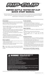
Barrel Blocker / Battery2Barrel Blockeralkaline batteryBarrel Blocker The barrel blocker is a very important piece of safety equipment – as important as goggles. It is used any time the <strong>Impulse</strong> (orany other paintball marker) is connected to an air source <strong>and</strong> is in an area where people are not protected by paintball goggles or paintball fieldnetting.The barrel blocker performs a very simple function. If the <strong>Impulse</strong> is accidentally fired, the barrel blocker catches the paintball to prevent accidentalinjury or damage. Although turning off the <strong>Impulse</strong> does serve as a safety mechanism to prevent it from firing, the barrel blocker has an advantagein that it is clearly visible to everyone that it is in use. It is important to make sure that the barrel blocker is securely in place when it is used. Toput the barrel blocker on the <strong>Impulse</strong>, slide it over the end of the barrel <strong>and</strong> loop the cords over the back of the marker. Adjust the cord lock sothat the barrel blocker is held snugly in place <strong>and</strong> cannot slip free.Pro Tip: Because the barrelblocker is visible to everyone <strong>and</strong>works with all markers, it is thest<strong>and</strong>ard safety device used anytime the <strong>Impulse</strong> is h<strong>and</strong>led insafe zones where goggles areoff.Battery The electronic components in the <strong>Impulse</strong> are powered by a single rectangular 9-volt battery. For optimal performance, alkaline batteries(ANSI type 1604A) should be used. Lower cost “heavy duty” zinc/carbon batteries do not last nearly as long, or deliver amperage as reliably <strong>and</strong>should be avoided. Most “9v” style rechargeable batteries will work with the <strong>Impulse</strong>, but their charge levels may not be accurately reported on the<strong>Impulse</strong> display. It is advisable to gain experience with any particular rechargeable battery before trusting an important game to it.Installing or changing the battery in the <strong>Impulse</strong> is simple. Use a 5/64-inch allen wrench to remove the two grip screws from the left side of themarker <strong>and</strong> open the rubber grip. The battery simply slides into place, contact side up. Battery orientation is important. The positive terminal ofthe battery (smaller of the two snap conectors) should be aligned towards the <strong>Impulse</strong> display screen, while the negative terminal (larger snap)should be towards the barrel. With the battery in place, close the grip <strong>and</strong> secure it with the two grip screws. Make sure the circuit board’sbattery contacts are pressed firmly under spring pressure against the battery terminals. If the fit is loose, slight bending of the contacts maybe necessary. Because the <strong>Impulse</strong> circuit board draws a very small amount of current from the battery even when it is turned off, it is best toremove the battery if the marker is going to be stored for a few weeks or more.WWW.<strong>JT</strong>PAINTBALL.COM<strong>Impulse</strong> Owner’s Manual v1.02 Copyright © 2013, <strong>JT</strong> <strong>Paintball</strong>, all rights reserved.
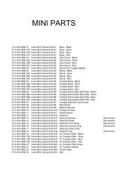
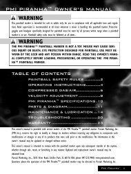
compressed air3ASA OFF ASA On ASA LOCK SCREWHPA The <strong>Impulse</strong> is designed to be powered by a high pressure compressed air (HPA) system only. Use of carbon dioxide (CO2) to power the<strong>Impulse</strong> is likely to cause damage to sensitive internal seals <strong>and</strong> will result in a voided warranty.<strong>Paintball</strong> HPA systems consist of an air storage cylinder rated to 3,000 psi or 4,500 psi <strong>and</strong> an integrated regulator/valve installed in the neck ofthe cylinder. HPA systems are typically divided into high-output (800 psi) <strong>and</strong> low-output (400 psi) models. Either type will work with the <strong>Impulse</strong>,though use of a high-output model will often deliver more consistent velocity at high rates of fire.HPA systems are shipped empty, <strong>and</strong> must be filled by properly trained persons. Once filled, the HPA system is attached to the <strong>Impulse</strong> byscrewing it in to the bottom-line ASA (See ASA).ASA The <strong>Impulse</strong> is equipped with a bottom-line style venting on/off Air System Adapter (ASA). Before screwing an HPA system into the ASA,make sure the ASA is turned off by turning the on/off lever forward. After screwing in the HPA system, the ASA may be turned on by turning theon/off lever back parallel with the ASA body. The ASA lever should be turned on slowly, so that the gas pressure inside the <strong>Impulse</strong> rises gently,rather than with a sudden “pop.”WARNING: When removingan HPA System from the ASAwatch carefully to make surethe HPA system regulator is unscrewingfrom the ASA <strong>and</strong> thatthe HPA cylinder is not unscrewingfrom the HPA regulator.WARNING: Never put oil orother hydrocarbon products inan HPA system or its fill nipple.When turning the ASA off, gas trapped between the ASA <strong>and</strong> vertical regulator will be released with a brief hissing sound. This is normal. Turningoff the ASA does not completely de-pressurize the <strong>Impulse</strong> <strong>and</strong> may leave enough gas inside the marker to fire 2 or more shots (see de-gassing).The ASA may be replaced with other similar gas mounts or fittings. To replace the ASA, first unload <strong>and</strong> de-gas the marker, then remove the HPAsystem. Use a 3/32-inch allen wrench through the middle hole in the bottom of the grip frame to loosen the ASA setscrew. Temporary threadlocking compound (Blue Loctite 242 or equivalent) is used to keep the ASA lock screw in place. The ASA may be replaced by one of a similar designwhich uses a 3/4-inch dovetail mounting rail, or an ASA which uses traditional center aligned 10-32 ASA mounting screws.WWW.<strong>JT</strong>PAINTBALL.COM<strong>Impulse</strong> Owner’s Manual v1.02 Copyright © 2013, <strong>JT</strong> <strong>Paintball</strong>, all rights reserved.
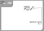
velocity7velocity adjustmentvelocity The velocity, or speed at which the <strong>Impulse</strong> fires a paintball must be measured <strong>and</strong> adjusted each day before use – both for fairness ofthe game <strong>and</strong> player safety. In an area where it is safe to fire paintballs, while wearing ASTM compliant eye <strong>and</strong> face protection for paintball, firethree or four shots over a chronograph to measure the velocity of the paintballs. Commercial paintball fields have an area with chronographs setaside for this purpose.If the velocity is above the paintball field’s limit, or above 300 feet per second (the internationally accepted safe velocity limit for 68 caliberpaintballs), it must be reduced. If the velocity is much below the field’s limit, adjusting it up closer to the limit will give the <strong>Impulse</strong> the most rangepossible as well as the best chance of breaking each paintball on target.If velocity adjustment is needed, use a 5/32-inch allen wrench to turn the velocity adjuster located in the bottom of the vertical regulator. Turn theallen wrench clockwise to increase velocity <strong>and</strong> counter-clockwise to decrease. Take three or four shots after every adjustment to allow the gaspressure inside the <strong>Impulse</strong> to stabilize then fire over the chronograph again to take another measurement. Adjust <strong>and</strong> re-check as needed untilthe desired velocity is reached. For safety reasons, never adjust the <strong>Impulse</strong> to fire at greater than 300 feet per second.Pro Tip: Checking velocity isan important safety procedurewhich must be performed everytime the <strong>Impulse</strong> is taken tothe field. For safety the velocitymust be kept under 300 feetper second, but getting as closeto the field’s limit as possiblewill maximize effective range.WWW.<strong>JT</strong>PAINTBALL.COM<strong>Impulse</strong> Owner’s Manual v1.02 Copyright © 2013, <strong>JT</strong> <strong>Paintball</strong>, all rights reserved.
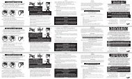
unloading / de-gassing8vision offdry fire to de-gasUnloading degassing At the end of each day’s use, <strong>and</strong> before performing cleaning or <strong>maintenance</strong> work on the <strong>Impulse</strong>, it must be unloaded<strong>and</strong> de-gassed. Take the <strong>Impulse</strong> to an area where it is safe to shoot, such as the chronograph area of a paintball field. While wearing paintballgoggles, remove the hopper from the <strong>Impulse</strong>. By turning the <strong>Impulse</strong> upside down, any extra paintballs can be emptied from the chamber <strong>and</strong>feed-neck.Turn the <strong>Impulse</strong> on, then de-activate the Vision anti-chop system by pressing the power button for one-half second until the eye icon in the <strong>Impulse</strong>display screen switches to an eye with a diagonal line through it.Pro Tip: Always unload <strong>and</strong>de-gas the <strong>Impulse</strong> beforetransporting it to or from thefield in a vehicle. In addition tobeing a good safety practice,some states require it by law.Dry fire the <strong>Impulse</strong> for 2 or three shots in a safe direction to be certain that there are no paintballs in the chamber or barrel.Turn off the HPA system by turning the bottom-line ASA lever out <strong>and</strong> away from the grip.WARNINGEven after the ASA has been turned off <strong>and</strong> the HPA system is removed, the valve chamber inside the <strong>Impulse</strong> may still be charged with enoughpressure to fire 2 or more shots.Continue to dry fire the <strong>Impulse</strong> in a safe direction until all of the gas pressure inside has been released. The only sound to be heard when pullingthe trigger should be the faint click of the solenoid valve inside the grip frame.Turn off the <strong>Impulse</strong>.Unscrew the HPA system from the bottom-line ASA.WWW.<strong>JT</strong>PAINTBALL.COM<strong>Impulse</strong> Owner’s Manual v1.02 Copyright © 2013, <strong>JT</strong> <strong>Paintball</strong>, all rights reserved.
PROGRAMMING LOCK9lock buttonunlockedLocking/Unlocking To comply with paintball field <strong>and</strong> tournament rules, the <strong>Impulse</strong> is equipped with a programming lock feature. When the<strong>Impulse</strong> is locked, the electronic settings which impact firing modes, rate of fire <strong>and</strong> velocity may not be changed. Because the lock button cannotbe accessed without tools, the <strong>Impulse</strong> complies with all major tournament <strong>and</strong> scenario rules as well as common paintball field practices.<strong>Impulse</strong> lock status can be easily checked by looking at the display screen when the marker is turned on. A padlock symbol appears closed whilethe marker is locked, <strong>and</strong> open while it is unlocked. To lock or unlock the <strong>Impulse</strong>, use a 5/64-inch allen wrench to remove the grip screws <strong>and</strong> openthe left side grip (see Battery Installation). With the marker turned on, momentarily press the lock button, located just below the trigger switch toswitch back <strong>and</strong> forth between locked <strong>and</strong> unlocked status.Pro Tip: The programminglock feature isn’t just fortournaments. Most commercialpaintball fields require that allmarkers be locked in such a waythat their firing modes <strong>and</strong> anyadjustments which can affectvelocity (including dwell) cannotbe accessed on the field withouttools.WWW.<strong>JT</strong>PAINTBALL.COM<strong>Impulse</strong> Owner’s Manual v1.02 Copyright © 2013, <strong>JT</strong> <strong>Paintball</strong>, all rights reserved.
programming settings (continued)12BPS BYP – Balls Per Second Bypass. This setting places an additional cap on the <strong>Impulse</strong>’s maximum rate of fire when the Vision system is bypassed, slowing the marker down toreduce the risk of chopping a paintball while firing “blind.” Balls Per Second Bypass has a default value of 10bps <strong>and</strong> is adjustable between 6 <strong>and</strong> 15 balls per second.KICK IN – Ramping Kick In – This setting applies only to the Ramping firing mode. Adjustable between 3 <strong>and</strong> 10, with a default value of 3, this setting determines how many shots mustbe fired at the Ramping Rate in order to begin firing more than one shot per trigger pull.RATE - Ramping Rate - This setting applies only to the Ramping firing mode. This is the rate at which the trigger must be pulled before the Ramping mode begins adding shots to rampup the rate of fire beyond one shot per trigger pull. Ramping rate ranges between values of 3 <strong>and</strong> 10 trigger pulls per second with a default value of five.SUSTAIN – Shots To Sustain Ramping – This setting applies only to the Ramping firing mode. Shots To Sustain determines how frequently the trigger must be pulled to maintain rampingonce it has started. Ramping mode will continue to fire multiple shots per trigger pull until the rate of trigger pulls drops below the Shots To Sustain Ramping value. Shots To SustainRamping is adjustable between 3 <strong>and</strong> 10 trigger pulls per second, with a default value of 5.TRIGG DB – Trigger Debounce – When the <strong>Impulse</strong> trigger is pulled, the trigger switch inside the grip frame will make a series of rapid electrical pulse, called “switch noise” at thebeginning of its signal to the circuit board’s microprocessor. Debounce functions in the <strong>Impulse</strong> software are used to filter out this switch noise so that it is not misinterpreted asmultiple trigger pulls. Signals from the trigger switch which last longer than the Trigger Debounce value (in milliseconds) are considered to be valid trigger pulls. The Trigger Debouncesetting can be adjusted from 1 to 25 milliseconds, with a default value of 7 milliseconds.MECH DB – Mechanical Debounce – When depending on how the various aspects of the <strong>Impulse</strong> are configured, it can be possible for vibration from the firing cycle to bounce thetrigger against the trigger switch <strong>and</strong> create a runaway firing condition. The <strong>Impulse</strong> software guards against this with its Mechanical Debounce function. Due to the low recoil of the<strong>Impulse</strong>, mechanical debounce is not usually needed, so this setting is normaly set at zero (off). Mechanical Debounce may be activated by setting its value to 1 (lowest), 10 (highest)or anywhere in-between.FSDO – First Shot Drop-Off Compensation – When a paintball marker is at rest between shots, there can be a tendency of the seals on moving parts to build up friction. This can resultin the first shot fired being at a slightly lower velocity than those following immediately after. First Shot Drop-Off Compensation counter-acts this effect by increasing the dwell time ofonly the first shot after the marker has been at rest. The default FSDO setting is 20 milliseconds, <strong>and</strong> it is adjustable between 0 <strong>and</strong> 25 milliseconds.FSDO TMR – First Shot Drop-Off Compensation Timer – This setting adjusts the amount of time the <strong>Impulse</strong> must be at rest before the First Shot Drop-Off Compensation is used. TheFSDO Timer is adjustable between 20 <strong>and</strong> 120 seconds, with a default value of 6.AUTO SD – Automatic Shutdown – Using the <strong>Impulse</strong> can be so fun <strong>and</strong> exhilarating that it can be easy to forget to turn it off. Automatic Shutdown turns off the <strong>Impulse</strong> to protect itsbattery if it is left on, but not being used. Automatic Shutdown can be turned off (value of 0) or set between 1 <strong>and</strong> 30 minutes. The default Automatic Shutdown time is 30 minutes.DISP BRT – Display Brightness – When adjustments are being made to the <strong>Impulse</strong>, its display screen will illuminate at full brightness. After a while of rest it will reduce its brightness toconserve battery power. This setting determines how dim the display becomes. A value of 1 is the dimmest, while 8 is the brightest (no dimming). The default value for this setting is 1.TIMER EN – Game Timer Engage – This setting turns the game timer on or off.TIMER - Game Timer – This setting is the number of minutes that will be on the game timer when the <strong>Impulse</strong> is turned on. The timer will begin counting down after the first shot isfired. The game timer is adjustable between 1 <strong>and</strong> 60 minutes, <strong>and</strong> its default value is 7 minutes.VERSION – This value indicates the version number of the installed <strong>Impulse</strong> software. It is useful for troubleshooting <strong>and</strong> making sure the <strong>Impulse</strong> software is upgraded to the currentrelease version.WWW.<strong>JT</strong>PAINTBALL.COM<strong>Impulse</strong> Owner’s Manual v1.02 Copyright © 2013, <strong>JT</strong> <strong>Paintball</strong>, all rights reserved.
field strip13barrelboltBarrel The <strong>Impulse</strong> barrel may be removed from the body by simply unscrewing it. This will provide fast <strong>and</strong> easy access to both ends of thebarrel to allow cleaning with a pull-through squeegee.Bolt removal The impulse bolt serves two functions - it pushes each paintball through the breech <strong>and</strong> into the barrel, <strong>and</strong> it seals the breech,providing a path for gas to flow from the balanced firing valve to the barrel where the gas exp<strong>and</strong>s to propel the paintball.The <strong>Impulse</strong> bolt may be removed while the marker is still charged with gas. Like the barrel though, paintball goggles must be worn while h<strong>and</strong>lingthe marker if it is charged. Before removing the barrel, remove the hopper, or at least turn it off before removing the bolt.Lift up on the link pin to disconnect the bolt from the piston, <strong>and</strong> slide the bolt out the back of the <strong>Impulse</strong>. If the barrel is still attached, this willallow a pull-through squeegee to be used on both the breech <strong>and</strong> the bolt, in one pass. It will also allow for more thorough cleaning with a sticksqueegee or fleece squeegee than simply swabbing through the barrel.Pro Tip: Nothing will get in theway of your game more than apaintball broken in the breechor barrel. Until it is cleaned, youwill face a drop in accuracy <strong>and</strong>often more breaks. When usingold or poorly stored paintballs,a folding squeegee can be yourbest friend on the field.When the bolt is out, inspect its o-rings <strong>and</strong> replace any that are damaged or torn. Do not lubricate the bolt or bolt o-rings. Exposure to oil orgrease can swell these parts, increasing friction.When re-installing the bolt, take care to make sure the link pin is aligned with the piston before pressing it down to lock the bolt in place. Whenthe <strong>Impulse</strong> is charged with gas, the piston will be in the rear position. If the <strong>Impulse</strong> is not charged, locating the piston position is important to besure that the link pin locks correctly into its groove in the piston.WWW.<strong>JT</strong>PAINTBALL.COM<strong>Impulse</strong> Owner’s Manual v1.02 Copyright © 2013, <strong>JT</strong> <strong>Paintball</strong>, all rights reserved.
trigger adjustment15pre-travel post-travel activation point resistance4-point adjustment The <strong>Impulse</strong> trigger features four adjustment points, allowing its feel to be customized to a variety of tastes. From thefactory, the trigger is adjusted for maximum reliable <strong>operation</strong>. Fine tuning will allow you to get the best possible performance out of your <strong>Impulse</strong>.All adjustments are made with a .050-inch allen wrench.Pre-Travel This adjustment determines the trigger’s position when it is at rest. The pre-travel adjustment screw is accessed by sliding an allenwrench up through a hole in the base of the trigger guard <strong>and</strong> then into an opening in the grip frame. Turning the screw inward adjusts the triggerback, shortening the trigger pull. It is important that the trigger be allowed to swing far enough forward that it consistently resets after each shot,or the <strong>Impulse</strong> may fail to fire.Pro Tip: The shortest <strong>and</strong>lightest trigger pull isn’t alwaysthe best trigger pull. Firingquickly requires a trigger pullthat is long enough to be easilyfelt <strong>and</strong> has enough resistancethat the trigger resets quicklyfor the next shot.POST-Travel This adjustment determines how far back the trigger may be pulled. The post-travel adjustment screw is located in the top of thetrigger area of the grip frame, just forward of the front of the trigger cut-out. Turning this screw inward shortens the trigger pull. It is importantthat the trigger be adjusted so that it comes to a stop against this screw. Allowing the trigger to be stopped by impacting the circuit board’strigger switch instead may result in damage to the circuit board, especially if the trigger is pulled aggressively.activation point Once the length of the trigger pull has been adjusted with its start <strong>and</strong> stop points, the activation point adjustment may bemodified to change the point during the trigger pull at which this <strong>Impulse</strong> fires. This adjustment screw is located in the center of the trigger’s face.Turning the screw inward moves the activation point closer to the start of the trigger pull. It is important to make sure that the combination of thepost-travel adjustment <strong>and</strong> activation point adjustment allow the trigger to be stopped by the post-travel screw <strong>and</strong> not the activation point screwpressing against the trigger switch, or non-warranty damage to the trigger switch <strong>and</strong> or circuit board may occur.resistance The trigger resistance adjustment consists of a screw located in the top, front of the trigger. Turning this screw inward moves itcloser to the trigger return magnet, increasing trigger resistance <strong>and</strong> improving trigger reset speed.WWW.<strong>JT</strong>PAINTBALL.COM<strong>Impulse</strong> Owner’s Manual v1.02 Copyright © 2013, <strong>JT</strong> <strong>Paintball</strong>, all rights reserved.
pressure balancing16secondary regulatorVertical Regulatorbalance The velocity <strong>and</strong> maximum firing rate of the <strong>Impulse</strong> depend on a balance of three settings. The dwell setting determines how long the <strong>Impulse</strong> will power its solenoid valveto drive the firing piston into the pressure balanced poppet valve. The pressure setting of the vertical regulator will determine the pressure of the gas used to fire the paintball. Thepressure setting of the secondary regulator will determine the force behind the firing piston when it strikes the poppet valve.The relationship of these three settings all affect how hard <strong>and</strong> how quickly the bolt <strong>and</strong> firing piston move, as well as the force <strong>and</strong> length of the burst of gas which fires the paintballthrough the barrel. These have a direct effect on the feel, sound signature, possible rates of fire <strong>and</strong> efficiency of the <strong>Impulse</strong>.If the secondary regulator is turned up (clockwise) too high, the <strong>Impulse</strong> will not shoot as smoothly. If the secondary regulator is turned down too low, velocity consistency will suffer.For best all-around performance, <strong>JT</strong> <strong>Paintball</strong> recommends the following initial set-up procedure for balancing, dwell <strong>and</strong> pressure settings. Further adjustments to personal taste maybe made from there. If additional adjustments make the marker feel unbalanced when firing or cause inconsistency, performing the pressure balancing procedure will restore smooth,reliable <strong>operation</strong>.With the <strong>Impulse</strong> unloaded <strong>and</strong> de-gassed, use a 1/8-inch allen wrench to turn the adjustment screw in the secondary regulator clockwise until it backs out flush with the front edge ofthe regulator’s body. Set the <strong>Impulse</strong> to fire in semi-automatic mode (see Programming) with a dwell value of 12 milliseconds (default dwell value).While wearing goggles, <strong>and</strong> in an area where it is safe to fire a paintball marker (such as the chronograph range at a paintball field) use a 5/32-inch-inch allen wrench to adjust thevertical regulator as needed until the <strong>Impulse</strong> fires paintballs over a chronograph consistently at 300 feet per second. Next, turn the secondary regulator’s setting inward (counterclockwise)<strong>and</strong> test fire <strong>and</strong> adjust until velocity decreases to 285 to 290 fps.Further adjustment for a different desired velocity may be made by adjusting the vertical regulator. For safety reasons never adjust the <strong>Impulse</strong> to fire at greater than 300 feet persecond.WWW.<strong>JT</strong>PAINTBALL.COM<strong>Impulse</strong> Owner’s Manual v1.02 Copyright © 2013, <strong>JT</strong> <strong>Paintball</strong>, all rights reserved.
piston cleaning17End cap <strong>and</strong> firing pistonend cap The body end cap provides a rear stopping point for the firing piston <strong>and</strong> protects the piston chamber from debris. After unloading <strong>and</strong>de-gassing the <strong>Impulse</strong>, unscrew the end cap by h<strong>and</strong> to remove. Inspect the end cap o-ring <strong>and</strong> replace if damaged. Do not lubricate this o-ring, itprovides friction to keep the end cap in place. When reinstalling the end cap, take care not to cross-thread it into the body.firing piston The firing piston is the primary moving part that drives the <strong>Impulse</strong> firing mechanism. Reduced pressure gas drives the pistonforward or back as needed to fire the marker. When the <strong>Impulse</strong> is charged, the firing piston is held in its rear position. When the <strong>Impulse</strong> is firedgas flow controlled by the solenoid valve drives the firing piston forward. When this happens, the link pin which is locked into the firing piston drivesthe bolt forward chambering a paintball <strong>and</strong> sealing the breech before the firing piston presses on the balanced firing valve, opening it to releasethe gas which will fire the shot.Pro Tip: Hard dives intobunkers <strong>and</strong> competing in s<strong>and</strong>or mud can eventually depositdebris around the firing piston,resulting in inconsistent velocity.The firing piston <strong>and</strong> pistonchamber should be cleaned aftera day’s use or a dive into losedirt or mud.With the bolt <strong>and</strong> body end cap removed, the firing piston should slide out the back of the <strong>Impulse</strong> body, simply by tipping the marker up. If thefiring piston does not slide out easily, this is a sign of contamination with paint or debris or over-lubrication. In these cases the piston may need tobe pushed out by using a soft tool like a wooden chopstick to push at it through the bolt link pin slot. Do not use a hard tool like a screwdriver asthis may scratch <strong>and</strong> damage the interior of the firing piston chamber.Clean the firing piston with a soft cloth <strong>and</strong> inspect its o-rings for damage, replace if necessary. Also inspect the firing piston bumper, located in ahollow in the back of the piston. If damaged or missing the bumper must be replaced. Firing the <strong>Impulse</strong> without the bumper can cause permanentdamage to the end cap. Lubricate the firing piston’s o-rings with low temperature paintball grease <strong>and</strong> reinstall it into the body smooth end first.WWW.<strong>JT</strong>PAINTBALL.COM<strong>Impulse</strong> Owner’s Manual v1.02 Copyright © 2013, <strong>JT</strong> <strong>Paintball</strong>, all rights reserved.
egulator removal18vertical regulatorsecondary RegulatorVertical Regulator The vertical regulator is the primary regulator for the <strong>Impulse</strong>, setting the pressure of the air used to launch paintballsfrom the barrel. Once the <strong>Impulse</strong> has been unloaded <strong>and</strong> de-gassed, removing the regulator is a simple task. Press the release ring on themacroline hose fitting at the bottom of the regulator <strong>and</strong> remove the hose. The regulator may then be unscrewed from its vertical adapter.When the vertical regulator is removed, also clean <strong>and</strong> inspect the filter screen which protects the <strong>Impulse</strong>’s internal components from dust orrust which may accompany “dirty” air fills. Be sure to lubricate the vertical regulator’s top o-ring with Dow-33 paintball marker grease <strong>and</strong> fullyseat the filter screen before reinstalling the vertical regulator.Secondary Regulator The secondary regulator is fed by low pressure air from the vertical regulator <strong>and</strong> reduces its pressure even further, toprovide the lower pressure gas used to move the firing piston back <strong>and</strong> forth. The secondary regulator may be removed for cleaning or to accessthe <strong>Impulse</strong> balanced firing valve.Pro tip: Old-school paintballerswill think of the second stageas an LPR, or Low PressureRegulator, but the verticalregulator already drops the airpressure to low levels, thanksto the <strong>Impulse</strong>’s balanced firingvalve.With the vertical regulator removed, unscrew the regulator lock screw from the vertical adapter. Gently twisting <strong>and</strong> pulling the secondaryregulator will remove it from the front of the <strong>Impulse</strong> body. This will also provide access to the firing valve core <strong>and</strong> valve spring.Carefully clean <strong>and</strong> inspect all parts before reassembly, replacing any damaged or torn seals, or the valve piston if it shows signs of wear. Uponre-assembly, be sure the secondary regulator is properly seated before reinstalling the regulator lock screw. If the regulator lock screw does notturn easily into its fully seated position, do not force it. Reposition the secondary regulator to make sure its retention slot is properly lined up withthe lock screw.WWW.<strong>JT</strong>PAINTBALL.COM<strong>Impulse</strong> Owner’s Manual v1.02 Copyright © 2013, <strong>JT</strong> <strong>Paintball</strong>, all rights reserved.
grip frame & valve body removal19grip framevalve bodygrip frame It is necessary to remove the <strong>Impulse</strong> grip frame to remove the trigger, Vision wiring harness, solenoid valve or <strong>Impulse</strong> balancedvalve body. Unnecessary removal of the grip frame should be avoided. To remove the grip frame from an unloaded <strong>and</strong> de-gassed <strong>Impulse</strong>, firstunscrew the vertical regulator or remove the bottom-line hose. Next, remove the rubber grip, then unplug the solenoid valve <strong>and</strong> Vision wiringharnesses from the circuit board. Remove both grip frame screws <strong>and</strong> slide the grip away from the body. Be careful not to snag the wiringconnections on the frame <strong>and</strong> strain the wires.When reassembling the grip to the body, be sure the wires are tucked correctly in place. Also be sure that the wires <strong>and</strong> internal hose are notpinched between the frame <strong>and</strong> the body or solenoid valve. If the grip frame does not fit flush to the body, it is probably due to a pinched wire, hoseor both. Do not over-tighten the grip screws to force it. Back the grip frame out <strong>and</strong> reposition the wires.valve body In normal <strong>operation</strong>, there should rarely if ever be a need to remove the balanced firing valve body. If this becomes necessary, firstremove the grip frame <strong>and</strong> regulators. Slide the solenoid valve supply hose out of its notch in the valve retainer clip <strong>and</strong> pull the valve retainer clipout from the bottom of the body. Note that the retainer clip also holds the trigger return magnet. With the retainer clip removed, the valve bodymay be slid out the front of the <strong>Impulse</strong> body. Do not use a hard tool like a screwdriver to push the valve body, as this may scratch <strong>and</strong> damagethe smooth surfaces inside the <strong>Impulse</strong> body, causing a leak. When the valve is out, inspect its o-rings <strong>and</strong> replace any that are damaged. Lightlylubricate the o-rings with Dow-33 based paintball marker grease prior to reassembly.Pro tip: A pressure balancedfiring valve is the key to the<strong>Impulse</strong>’s smooth firing cycle.Opposing piston faces balanceatmospheric pressure againstthe firing gas pressure for avalve that can be opened withvery little force by a light firingpiston. Without a heavy ram orhammer to shake the <strong>Impulse</strong>off target, it shoots smooth assilk.When reassembling, the end of the valve body with wrench flats faces the front of the <strong>Impulse</strong>. Make sure the valve body is lined up properly withthe <strong>Impulse</strong> body. A small hole in the bottom of the valve body must be lined up with a locator pin in the middle of the U shaped valve retainer clip.If the valve is not lined up correctly, the retainer clip will not slide all the way into the body. Once the valve retainer clip is reinstalled be sure towedge the solenoid valve supply hose back into the retainer clip’s notch so that it does not become pinched between the body <strong>and</strong> grip frame.WWW.<strong>JT</strong>PAINTBALL.COM<strong>Impulse</strong> Owner’s Manual v1.02 Copyright © 2013, <strong>JT</strong> <strong>Paintball</strong>, all rights reserved.
trigger & solenoid removal20triggersolenoid valvetrigger Aftermarket triggers are a common customization accessory. To change out the <strong>Impulse</strong> trigger, first remove the grip frame, Next,use a 3/32-inch allen wrench to loosen the two trigger-pivot screws on either side of the grip frame. The trigger pivot screws do not need to beremoved, just backed out far enough that they release the trigger. Lower <strong>and</strong> rotate the trigger out the out grip frame.When installing a new trigger, be sure it is designed for the <strong>JT</strong> <strong>Impulse</strong>. Triggers designed for earlier generation <strong>Impulse</strong> markers are notcompatible. Screw the trigger mount screws in evenly from each side. The screws should just be tight enough to hold the trigger securely in place.Do not overtighten the trigger pivot screws or binding of the trigger bearings may result.See the trigger adjustment section of this <strong>manual</strong> for proper adjustment of a new trigger. Incorrect adjustment may result in damage to the<strong>Impulse</strong> circuit board.Solenoid valve As with the trigger, the grip frame must be removed to replace the <strong>Impulse</strong> solenoid valve. Generally, removal of the solenoidvalve should be avoided except when necessary for replacement. To remove the solenoid valve, use a 1/8-inch allen wrench to unscrew the solenoidvalve bracket screw <strong>and</strong> lift away the solenoid valve bracket.Pro tip: Old school paintballerswill typically refer to the solenoidvalve simply as a solenoid,but there is a difference. Asolenoid uses electromagneticenergy to provide a pushing orpulling force. A solenoid valvecontains a small solenoid whichopens or closes a valve thatcontrols gas flow. Low-endelectronic grip markers usesolenoids. Tournament levelelectropneumatic markersfeature solenoid valves.Three small o-rings rest in grooved openings in the manifold plate, creating a seal between it <strong>and</strong> the solenoid valve. Two similar o-rings sealthe plate to the body. These o-rings must be clean <strong>and</strong> undamaged - if they are not, they should be replaced. Lubrication of these o-rings is notnecessary, but a very thin bit of Dow-33 paintball marker grease may be used to help them stay in their slots during re-assembly. Take extremecare here, as any excess grease can clog <strong>and</strong> damage the solenoid valve. A new solenoid valve is installed by pressing it up against the <strong>Impulse</strong>body, then locking it in place with the solenoid valve bracket <strong>and</strong> bracket screw. The hose connecting the manifold plate to the secondary regulatoroutput is a single-use hose. If it is removed from the brass barb at the front of the body, or the barb on the manifold plate it will have stretched<strong>and</strong> must be replaced. It is very likely to leak if re-used.WWW.<strong>JT</strong>PAINTBALL.COM<strong>Impulse</strong> Owner’s Manual v1.02 Copyright © 2013, <strong>JT</strong> <strong>Paintball</strong>, all rights reserved.
troubleshooting21<strong>Impulse</strong> WILL NOT TURN ON:• Test using a br<strong>and</strong> new alkaline 9v battery.• Open the rubber grip, as when changing the battery, <strong>and</strong> inspect to make sure nodebris is preventing the power button from pressing the power switch on the <strong>Impulse</strong>circuit board.BREAKING PAINT:• Paint to barrel match is wrong. The paint you are using has absorbed moisture <strong>and</strong>grown too large for the barrel you are shooting it through.• Ball Detents are damaged or missing. See <strong>manual</strong> section on ball detents. Inspect<strong>and</strong> replace detents if damaged or missing.• Paint is too low quality, improperly shipped, stored or too brittle. Switch to fresh <strong>JT</strong>or Empire paintballs.• Turn on the Vision anti-chop system.• Check the <strong>Impulse</strong> battery. It may be low, causing incomplete cycling.• Loader may not be keeping up. Check loader batteries or use a faster loader.<strong>Impulse</strong> TURNS ON BUT WILL NOT FIRE:• Test using a br<strong>and</strong> new alkaline 9v battery.• Make sure the trigger adjustments allow the trigger to activate the trigger switchwhen pulled, <strong>and</strong> reset when released.• Make sure the bolt pin is correctly seated in the firing piston.• Clean the bolt <strong>and</strong> breech.• Reset the dwell setting to default with a factory reset.• Increase the secondary regulator pressure.AIR LEAKS DOWN THE BARREL WHEN GASSING UP THE <strong>Impulse</strong> :• The rear face of the firing valve core is dirty or damaged. See the regulator removalsection of this <strong>manual</strong>, clean <strong>and</strong> inspect the firing valve core, replace if damaged.• Make sure valve spring is installed correctly.LEAK BETWEEN GRIP FRAME AND BODY:• Inspect <strong>and</strong> if damaged replace the firing piston o-rings.• If leak continues, inspect <strong>and</strong> if damaged replace the solenoid valve o-rings.LEAK FROM FRONT OF MARKER• Inspect, lubricate, <strong>and</strong> if damaged, replace the front o-ring on the secondaryregulator.THE IMPULSE HAS FIRST SHOT DROP OFF (FSDO)• Clean, lubricate <strong>and</strong> inspect the bolt, firing piston <strong>and</strong> firing valve core.• Increase the second-stage regulator pressure.• Reset circuit board to factory default settings.• Increase the FSDO setting value.TRIGGER IS STUCK AND WILL NOT MOVE FREELY:• Make sure the trigger mount screws have not been overtightened. Loosen themslightly.• Remove the grip frame <strong>and</strong> remove the trigger. Clean any debris that may beimpeding trigger movement.THE IMPULSE LEAKS FROM TOP OF VERTICAL REGULATOR:• The pressure setting of the vertical regulator may be too high, resulting in excesspressure being vented from the pressure relief valve to protect the solenoid valve.Reduce the pressure setting as when reducing velocity.• Check the ASA o-ring at the top of the vertical regulator. Replace if necessary.• The pressure relief valve may be leaking. See a qualified <strong>JT</strong> service center forassistance in repairing the vertical regulator.<strong>Impulse</strong> : FIRES, BUT VELOCITY DROPS UNDER RAPID FIRE:• Make sure the <strong>Impulse</strong> battery is fully charged.• Increase the secondary regulator pressure.• If problem persists, clean <strong>and</strong> inspect regulators.REGULATOR LEAK OR CLIMB IN PRESSURE:• Clean both regulators, inspect, <strong>and</strong> if necessary replace their piston seats.LEAK IN THE GRIP FRAME, NEAR THE REGULATORS:• Clean <strong>and</strong> inspect both regulators.• Inspect <strong>and</strong> replace any o-rings that show signs of damage.RELIEF VENT AREAWWW.<strong>JT</strong>PAINTBALL.COM<strong>Impulse</strong> Owner’s Manual v1.02 Copyright © 2013, <strong>JT</strong> <strong>Paintball</strong>, all rights reserved.
parts diagrams22IMPBFTOB7018IMPBBKOB7018barrelWWW.<strong>JT</strong>PAINTBALL.COM<strong>Impulse</strong> Owner’s Manual v1.02 Copyright © 2013, <strong>JT</strong> <strong>Paintball</strong>, all rights reserved.
parts diagrams23IMp133IMP132IMp135OB9004SSC006imp134SSC008clamping feedneckWWW.<strong>JT</strong>PAINTBALL.COM<strong>Impulse</strong> Owner’s Manual v1.02 Copyright © 2013, <strong>JT</strong> <strong>Paintball</strong>, all rights reserved.
parts diagrams24OB9015VRG105OM7014VRG106SPR034imp105OB7010OB7014IMP104VRG102VRG109OM7006OM7014VRg107spr035OM9006OM7014FIT005OB7010VRG108FLT002CLP006OM9006vertical regulatorVRG104CLP005WWW.<strong>JT</strong>PAINTBALL.COM<strong>Impulse</strong> Owner’s Manual v1.02 Copyright © 2013, <strong>JT</strong> <strong>Paintball</strong>, all rights reserved.
parts diagrams25IMP127IMP129SPR011IMP128FLT003SPR006IMP126VRG106OB7010OB7013OB7010OB7015secondary regulatorWWW.<strong>JT</strong>PAINTBALL.COM<strong>Impulse</strong> Owner’s Manual v1.02 Copyright © 2013, <strong>JT</strong> <strong>Paintball</strong>, all rights reserved.
parts diagrams26IMP108IMP109SPR005IMP110OB7014 OB7014 OB7014BOLTWWW.<strong>JT</strong>PAINTBALL.COM<strong>Impulse</strong> Owner’s Manual v1.02 Copyright © 2013, <strong>JT</strong> <strong>Paintball</strong>, all rights reserved.
parts diagrams27IMP102BUM003IMP103OB7009OB9010OB7011OB7010OB7012pistonWWW.<strong>JT</strong>PAINTBALL.COM<strong>Impulse</strong> Owner’s Manual v1.02 Copyright © 2013, <strong>JT</strong> <strong>Paintball</strong>, all rights reserved.
parts diagrams28OU7005OB7008SPR004IMP124IMP122 assemblyOU9012OB7014OB7014OB7010valveWWW.<strong>JT</strong>PAINTBALL.COM<strong>Impulse</strong> Owner’s Manual v1.02 Copyright © 2013, <strong>JT</strong> <strong>Paintball</strong>, all rights reserved.
parts diagrams29imp111SPR003imp113SPR003imp111SSB010imp112SSB010Vision covers / detentsWWW.<strong>JT</strong>PAINTBALL.COM<strong>Impulse</strong> Owner’s Manual v1.02 Copyright © 2013, <strong>JT</strong> <strong>Paintball</strong>, all rights reserved.
parts diagrams30IMP101IMP121IMP125MAG004HOS005IMP119OB7M002OB7M13imp114imp130SSB007SSB007OB7M002 (3x)flt001IMPULSE SOLENOIDVALVE ASSEMBLYIMP115bodyWWW.<strong>JT</strong>PAINTBALL.COMSSB006<strong>Impulse</strong> Owner’s Manual v1.02 Copyright © 2013, <strong>JT</strong> <strong>Paintball</strong>, all rights reserved.
parts diagrams32OB7010OB7005VLV406IMP136VLV405VLV404IMP136IMP137SSF003VLV402FIT005OB7010OB7010bottmline asaWWW.<strong>JT</strong>PAINTBALL.COM<strong>Impulse</strong> Owner’s Manual v1.02 Copyright © 2013, <strong>JT</strong> <strong>Paintball</strong>, all rights reserved.
warranty information33LIMITED LIFETIME WARRANTY INFORMATION(ORIGINAL PURCHASE RECEIPT REQUIRED)KEE Action Sports (“KEE”) warrants that this product is free from defects in materials <strong>and</strong> workmanship for as long as it is owned by the original purchaser, subject to theterms <strong>and</strong> conditions set forth below. KEE Action Sports will repair or replace with the same or equivalent model, without charge, any of its products that have failed innormal use because of a defect in material or workmanship.KEE Action Sports is dedicated to providing you with products of the highest quality <strong>and</strong> the industry’s best product support available for satisfactory play.Purchaser should register product to activate warranty. Register your product by:1. Online at www.paintballsolutions.com2. Complete the product registration card (if applicable) <strong>and</strong> mail along with a copy of your receipt to <strong>Paintball</strong> <strong>Solutions</strong>, 11723 Lime Kiln Rd., Neosho, MO 64850.WHAT THIS WARRANTY DOES NOT COVERThis warranty does not cover problems resulting from abuse, the unauthorized modification or alteration of our product, problems resulting from the addition of aftermarketproducts <strong>and</strong> scratches or minor superficial imperfections. Due to the nature of paintball products it is important that the product be maintained by the user as indicatedin the product <strong>manual</strong> to remain in good operating condition. Your Limited Lifetime Warranty will be void if you fail to maintain the product as recommended in the productinstruction <strong>manual</strong>. In addition, certain parts of a product may be subject to wear through regular usage. Replacement <strong>and</strong> repair of such parts is the responsibility ofthe user throughout the life of the product. These parts are not covered under the Limited Warranty. Examples of this type of part include (but are not limited to) gogglelens, straps, O-ring seals, cup seals, springs, ball détentes, batteries, hoses, drive belts, gears <strong>and</strong> any part of a product subject to continuous impact from paintballs.Hydrotesting of air cylinders is not covered under this warranty.The Limited Lifetime Warranty also does not cover incidental or consequential damages. This warranty is the sole written warranty on KEE’s product <strong>and</strong> limits any impliedwarranty to the period that the product is owned by the original purchaser.Some states, provinces <strong>and</strong> nations do not allow the limitation of implied warranties or of incidental or consequential damages, so the above limitations or exclusions maynot apply to you. This warranty gives you specific legal rights <strong>and</strong> you may also have other rights which vary from state to state, province to province, nation to nation. Ifyou should encounter any problems with your product <strong>and</strong> you have added aftermarket parts on your product, please test it with the original stock parts before sending itin.Always unload <strong>and</strong> remove air supply before shipping markers. Do not ship your air supply tank if it is not completely empty. Shipping a pressurized air supply tank is unsafe<strong>and</strong> unlawful. Remove all batteries from products prior to shipping.This Limited Warranty gives you specific legal rights, <strong>and</strong> you may also have other rights which vary from state to state. Some states do not allow the exclusion ofincidental or consequential damages.For Warranty parts, service, information or <strong>manual</strong>s in other languages, (where applicable) go to:<strong>Paintball</strong> <strong>Solutions</strong>: www.paintballsolutions.comE-Mail: tech@paintballsolutions.comTelephone: 1-800-220-322211723 Lime Kiln Rd., Neosho, MO 64850WWW.<strong>JT</strong>PAINTBALL.COM<strong>Impulse</strong> Owner’s Manual v1.02 Copyright © 2013, <strong>JT</strong> <strong>Paintball</strong>, all rights reserved.