Zero-voltage switching for three-level capacitor clamping ... - Ivo Barbi
Zero-voltage switching for three-level capacitor clamping ... - Ivo Barbi
Zero-voltage switching for three-level capacitor clamping ... - Ivo Barbi
- No tags were found...

You also want an ePaper? Increase the reach of your titles
YUMPU automatically turns print PDFs into web optimized ePapers that Google loves.
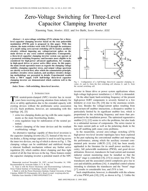
774 IEEE TRANSACTIONS ON POWER ELECTRONICS, VOL. 14, NO. 4, JULY 1999Fig. 5.Theoretical commutation wave<strong>for</strong>ms <strong>for</strong> the proposed true PWM pole <strong>three</strong>-<strong>level</strong> <strong>capacitor</strong> <strong>clamping</strong> inverter in an entire <strong>switching</strong> cycle.Fig. 5, diode-to-switch commutation ( ) and switchto-diodecommutation ( ) are depicted by andin Fig. 7, respectively. The two arrows stand <strong>for</strong> theradiuses of the two resonances in the commutation process.A. Total Commutation DurationFor diode-to-switch ( to ) commutation, the unit valueof the total commutation durationis given byEquations (1) and (2) are graphically shown in Fig. 8(a) and(b).B. Auxiliary Device Peak Current StressFor diode-to-switch ( to ) commutation, the unitvalue of the auxiliary switch ( ) peak current can berepresented by(3)(1)For switch-to-diode ( to ) commutation, the unit valueof the total durationis given byFor switch-to-diode ( to ) commutation, the unitvalue of the auxiliary switch ( ) peak current can berepresented by(4)(2)As shown in Fig. 9(a) and (b), <strong>for</strong> diode-to-switch (to ) commutation, the peak current of the corresponding
YUAN AND BARBI: ZERO-VOLTAGE SWITCHING FOR THREE-LEVEL INVERTER 775Fig. 6.Operation step diagrams <strong>for</strong> the first sampling cycle.C. Auxiliary Device RMS Current StressThe resonant inductor rms current stress over <strong>switching</strong>period resulting from diode-to-switch commutationcan be expressed by(5)Fig. 7. Phase plane of the resonance between Lr14 and Cr4 during thewhole commutation process of the second pole.whereauxiliary switch increases with the load current. For switchto-diodecommutation ( to ), however, it decreases withthe load current.
776 IEEE TRANSACTIONS ON POWER ELECTRONICS, VOL. 14, NO. 4, JULY 1999(a)(b)Fig. 8. Variations of commutation durations t95 and t1311 with load current and trans<strong>for</strong>mer ratio: (a) diode-to-switch commutation and (b)switch-to-diode commutation.(a)(b)Fig. 9. Variations of the auxiliary switch peak currents with load current and trans<strong>for</strong>mer ratio: (a) diode-to-switch commutation and (b) switch-to-diodecommutation.Similarly, the resonant inductor rms current resulting fromswitch-to-diode commutation is expressed byThe auxiliary switch rms current during diode-to-switch commutationand switch-to-diode commutationare equal to and , respectively, and the relationshipsare shown in Fig. 10(a) and (b). The resonant inductorrms current can then be described by(7)where(6)V. DESIGN METHODOLOGY OF THE AUXILIARY CIRCUITRYA. Autotrans<strong>for</strong>mer RatioTo ensure ZVS in the presence of losses (device conductionloss, resonant inductor loss, resonant <strong>capacitor</strong> loss, etc.),autotrans<strong>for</strong>mer ratio should meet(8)
YUAN AND BARBI: ZERO-VOLTAGE SWITCHING FOR THREE-LEVEL INVERTER 777(a)(b)Fig. 10. Variations of the auxiliary switch rms currents with load current, trans<strong>for</strong>mer ratio, and <strong>switching</strong> period: (a) diode-to-switch commutation and(b) switch-to-diode commutation.where and represents the equivalent resistancein the resonance loop. Equation (8) can be simplified toB. Resonant FrequencyThe resonant frequency can be set by optimizing the rmsstress of the auxiliary switch according to Fig. 10(a) based onthe <strong>switching</strong> frequency of the system.C. Resonant Capacitor and Resonant InductorThe resonant capacitance should be optimized <strong>for</strong> the mainswitch turn-off loss [20]. Based on the resonant frequency andthe resonant capacitance, the resonant inductance is decided.D. Auxiliary Switch Gating Signal Width andMinimum PWM ON/OFF TimeThe minimum width of the auxiliary switch gating signalmust be set above the maximum value of the commutationduration, as demonstrated in Fig. 8(a). In the same sense, theminimum PWM ON/OFF time ( and as shownin Fig. 5) should also be set above this value.E. Rating of the Auxiliary SwitchDue to the zero-current <strong>switching</strong> (ZCS) in the auxiliarycircuitry and due also to the high-<strong>switching</strong> frequency withrespect to the thermal inertia of the device, the rating of theauxiliary switch should be chosen according to its rms stressas illustrated in Fig. 10(a). However, auxiliary switch peakcurrent illustrated in Fig. 9(a) should not exceed the devicepeak output current rating.VI. EXPERIMENTATIONA proof-of-concept IGBT half-bridge inverter, as shownin Fig. 11(a), has been built with the specifications shown(9)in Table I. Designing results of the resonant and trans<strong>for</strong>merparameters according to Section V are shown in Table II.As a result of the above designing, the resultant maximumcommutation duration is 11.3 s. The maximum peak andrms currents of the auxiliary switch are 54.2 and 8.4 A,respectively. Thus, the auxiliary switch gating signal width isset at 15 s and the minimum PWM ON/OFF time is set at 25s. Four SEMIKRON IGBT modules (SKM50GB123D, 1200V/50 A) are employed as the main and auxiliary switches, andeight ultrafast international rectifier diodes (HFA30TA60C,630 V/30 A) work as the auxiliary diodes. Two storage<strong>capacitor</strong>s and each rated at 360 V/3300 F <strong>for</strong>mthe center tap. A low-pass filter (mH,F) is installed at the output. Besides, a <strong>voltage</strong> monitoringcircuit as shown in Fig. 11(b) is installed across eachmain device to release the turn-on gating signal when thedetected <strong>voltage</strong> is zero. Such monitoring is essential <strong>for</strong>ensuring ZVS because of the load current dependant fractionin the pole dead time taken <strong>for</strong> the conducting diode toblock which makes constant dead time setting not possible.Fig. 12 shows the output load side <strong>voltage</strong> and filter inductorcurrent wave<strong>for</strong>ms. Fig. 13 shows the <strong>three</strong>-<strong>level</strong> output<strong>voltage</strong> .Fig. 14 shows the ZVS commutation process of the mainswitch during <strong>switching</strong> cycle. Furthermore, in Fig. 15, thedetails of turning on at A are shown. For a predictedof 90 V/ s (averaged over ) and of 14A/ s, the experimental values are about 90 V/ s and 13 A/ s,respectively. In Fig. 16, the details of turning-off atA are shown. For a predicted of 152 V/ s (averagedover ), the experimental value is about 146 V/ s.Fig. 17 shows the ZCS commutation process of the auxiliaryswitch ( ) at A. For the predicatedcommutation duration of 9.8 s according to Fig. 8(a) andthe predicated peak current of 46.3 A according to Fig. 9(a),the experimental values are 9.5 s and 46.5 A, respectively.
778 IEEE TRANSACTIONS ON POWER ELECTRONICS, VOL. 14, NO. 4, JULY 1999(a)(b)Fig. 11. (a) Prototype configuration of the half-bridge modified true PWM pole <strong>capacitor</strong> <strong>clamping</strong> inverter and (b) <strong>voltage</strong> monitoring circuit interfacingthe SEMIKRON SKHI10 driver with the main IGBT device.TABLE IPROTOTYPE SPECIFICATIONSTABLE IIRESONANT AND TRANSFORMER DESIGNING RESULTS
YUAN AND BARBI: ZERO-VOLTAGE SWITCHING FOR THREE-LEVEL INVERTER 779Fig. 12. Experimental output <strong>voltage</strong> and filter inductor current (V O andi load ).Fig. 16. Extended turn-off process of S 3 .Fig. 13. Experimental inverter output <strong>voltage</strong> V AO .Fig. 17. ZCS commutation of the auxiliary switch (S a3 ).Fig. 18. Resonant inductor current wave<strong>for</strong>m at i load =0A.Fig. 14. ZVS commutation of the main switch (S 3 ).Fig. 19. Resonant inductor current wave<strong>for</strong>m at i load =22A.Fig. 15. Extended turn-on process of S 3 .Fig. 18 shows the resonant inductor current wave<strong>for</strong>m whenA. For the predicated commutation duration of 5.9s and the predicated peak current of 24.1 A, the experimentalvalues are about 5.5 s and 23.5 A, respectively. In the meantime,Fig. 19 shows the resonant inductor current wave<strong>for</strong>mwhenA. The experimental commutation durationand peak current are about 9.5 s and 46.5 A, which are inaccordance with the predicated values of 9.8 s and 46.3 Aaccording to Figs. 8(a) and 9(a), respectively.Measured efficiency of the prototype reaches 95% at fullload.VII. CONCLUSIONFrom the theoretical and experimental studies reportedabove, the following conclusions can be drawn.
780 IEEE TRANSACTIONS ON POWER ELECTRONICS, VOL. 14, NO. 4, JULY 1999• The proposed technique achieves zero-<strong>voltage</strong> commutationof the main devices in the <strong>three</strong>-<strong>level</strong> <strong>capacitor</strong><strong>clamping</strong> inverter with the help of a small rating zerocurrent commutation auxiliary circuitry without incurringany additional spikes over the main devices and yetwithout necessitating any extra control complexities.• The proposed technique assumes no modulation limitationsexcept <strong>for</strong> a small duty-cycle loss comparable tothat demanded by a conventional snubber.• Validity of the theoretical analysis <strong>for</strong> the commutationprocess is verified by experimental results from a scaledprototype.• The proposed technique is suitable <strong>for</strong> high-power advancedapplications due to the reduced loss, increasedoperating frequency, and the widened system bandwidth.The right-hand four components correspond to , ,, and , respectively.For switch-to-diode commutation, the total commutationduration is given by (A2) at the bottom of the page. Theright-hand components correspond to and ,respectively.Equations (1) and (2) can be obtained from (A1) and (A2)by multiplying both sides of each by .B. Auxiliary Device Peak Current StressFor diode-to-switch commutation, the peak currentgiven byis(A3)APPENDIXBRIEF DEDUCTION OF (1)–(6)A. Total Commutation DurationFor diode-to-switch commutation, the total commutationduration is given byFor switch-to-diode commutation, the peak currentgiven byis(A4)Equations (3) and (4) can be obtained by dividing both sidesof (A3) and (A4) by .(A1)C. Auxiliary Device RMS Current StressThe resonant inductor rms current stress over the <strong>switching</strong>period resulting from diode-to-switch commutation is(A2)(A5)(A7)
YUAN AND BARBI: ZERO-VOLTAGE SWITCHING FOR THREE-LEVEL INVERTER 781given by (A5) at the bottom of the previous page, whereThe right-hand <strong>three</strong> components in (A5) correspond to intervals, , and , respectively.Similarly, the resonant inductor rms current over the <strong>switching</strong>period resulting from switch-to-diode commutationis given by(A6)as shown in (A7), given at the bottom of the previous page.The right-hand two components in (A6) correspond toand , respectively.Equations (5) and (6) can be obtained by dividing both sidesof (A5) and (A6) by .REFERENCES[1] H. Stemmler and P. Guggenbach, “Configurations of high-power <strong>voltage</strong>source inverter drives,” in European Conf. Power Electronics andApplications (EPE), 1993, pp. 7–14.[2] T. Katta and Y. Kurokawa, “Advanced inverter control system usinghigh <strong>voltage</strong> IGBT <strong>for</strong> EMU,” in Int. Power Electronics Conf., 1995,pp. 1060–1065.[3] G. J. Hatziadoniu and F. E. Chalkiadakis, “A 12-pulse static synchronouscompensator <strong>for</strong> the distribution system employing the <strong>three</strong>-<strong>level</strong> GTOinverter,”IEEE Trans. Power Delivery, vol. 12, Oct. 1997.[4] A. Steimel, “Electric railway traction in Europe,” IEEE Ind. App. Mag.,pp. 7–17, Nov./Dec. 1996.[5] C. Schauder, M. Gernhardt, E. Stacey, T. Lemak, L. Gyugyi, T.W. Cease, and A. Edris, “Development of a 0100 MVAR staticcondenser <strong>for</strong> <strong>voltage</strong> control of transmission systems,” IEEE Trans.Power Delivery, vol. 10, pp. 1486–1496, July 1995.[6] T. Maruyama and M. Kumano, “New PWM control <strong>for</strong> a <strong>three</strong>-<strong>level</strong>inverter,” in Int. Power Electronics Conf., 1990, pp. 870–877.[7] T. A. Meynard and H. Foch, “Multi<strong>level</strong> converters and derived topologies<strong>for</strong> high power conversion,” in Int. Conf. Industrial Electronics,Control, and Instrumentation (IECON), 1995, pp. 21–26.[8] P. Carrére, T. Meynard, and J. P. Lavieville, “4000 V–300 A eight<strong>level</strong>IGBT inverter leg,” in European Conf. Power Electronics andApplications, 1995, pp. 1106–1111.[9] E. Gatti, G. Mazzorin, G. Tomassini, and G. Torri, “Large power <strong>voltage</strong>source inverters <strong>for</strong> industrial drives,” in IEEE Power ElectronicsSpecialists Conf., 1996, pp. 1059–1064.[10] L. Fratelli, “Dual-<strong>voltage</strong> high power converter <strong>for</strong> distributed powersystem in heavy traction using high <strong>voltage</strong> IGBT’s,” in IEEE PowerElectronics Specialists Conf., 1996, pp. 1414–1419.[11] A. Agbossou, I. Rasoanarivo, and B. Davat, “A comparative study ofhigh power IGBT model behavior in <strong>voltage</strong> source inverter,” in IEEEPower Electronics Specialists Conf., 1996, pp. 56–61.[12] F. C. Zach, K. H. Kaiser, J. W. Kolar, and F. J. Haselsteiner, “Newlossless turn-on and turn-off (snubber) networks <strong>for</strong> inverters, includingcircuits <strong>for</strong> blocking <strong>voltage</strong> limitation,” IEEE Trans. Power Electron.,vol. 1, pp. 65–75, Apr. 1986.[13] G. Bingen, “Utilization de transistors a <strong>for</strong>t courant et tension elevee,”in European Conf. Power Electronics and Applications (EPE), 1987,pp. 1.15–1.20.[14] R. W. De Doncker and J. P. Lyons, “The auxiliary resonant commutatedpole converter,” in IEEE Industrial Application Soc. Annu. Meeting,1990, pp. 1228–1235.[15] F. R. Salberta and J. S. Mayer, “An improved control strategy <strong>for</strong> a50 kHz auxiliary resonant commutated pole converter,” in IEEE PowerElectronics Specialists Conf., 1997, pp. 1246–1252.[16] K. Iida et al., “The influence of the conducting inductance in the auxiliaryresonant commutated pole inverter,” in IEEE Power ElectronicsSpecialists Conf., 1997, pp. 1238–1245.[17] H. J. Beukes, J. H. R. Enslin, and R. Spee, “Integrated active snubber<strong>for</strong> high power IGBT modules,” in IEEE Power Electronics SpecialistsConf., 1997, pp. 161–167.[18] I. <strong>Barbi</strong> and D. C. Martins, “A true PWM zero-<strong>voltage</strong> <strong>switching</strong> polewith very low additional rms current stress,” in IEEE Power ElectronicsSpecialists Conf., 1991, pp. 261–267.[19] L. L. Erhartt, K. Edelmoser, M. Sedlacek, and F. C. Zach, “A novellow-loss <strong>switching</strong> method <strong>for</strong> converters using turn-off power IG-BTs/GTO’s,” in European Conf. Power Electronics and Applications(EPE), 1993, pp. 46–51.[20] R. L. Steigerwald, R. W. De Doncker, and M. Kheraluwala, “Acomparison of high power dc–dc soft switched converter topologies,”IEEE Trans. Ind. Applicat., vol. 32, pp. 1139–1145, Sept./Oct. 1996.Xiaoming Yuan (S’97–M’99) was born in Anhui,China, on May 30, 1966. He received the B.Eng.degree from Shandong University of Technology,China, the M.Eng. degree from Zhejiang University,China, and the Dr.Eng. degree from the Federal Universityof Santa Catarina, Florianópolis, Brazil, in1986, 1993, and 1998, respectively, all in electricalengineering.From 1986 to 1990, he was with Qilu PetrochemicalCorporation, China, as a CommissioningEngineer <strong>for</strong> power system protective relay,adjustable-speed drives, and UPS systems. He is currently a Post-DoctoralResearcher with the Power Electronics and Electrometrology Laboratory,Swiss Federal Institute of Technology, Zurich, Switzerland, where he isworking on flexible ac transmission system (FACTS) devices.<strong>Ivo</strong> <strong>Barbi</strong> (M’78–SM’90), <strong>for</strong> a photograph and biography, see this issue,p. 635.