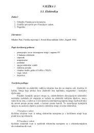
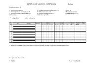
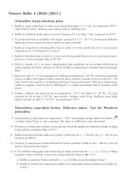
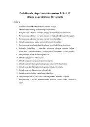
28.14 Semiconductor Devices 929I (mA)504030IAp∆V+ –Forward bias(a)nI 0 20 mA2010–1.0 –0.5Reverse bias(b)0.5 1.0Forward biasFigure 28.28 (a) Schematic of a p–n junction under forward bias. (b) The characteristic curve for areal p–n junction.∆V (V)where q is the electron charge, k B is Boltzmann’s constant, and T is the temperaturein kelvins. Figure 28.28 shows an I–V plot characteristic of a real p–n junction,along with a schematic of such a device under forward bias.The most common use of the semiconductor diode is as a rectifier, a device thatchanges 120-V AC voltage supplied by the power company to, say the 12-V DC voltageneeded by your music keyboard. We can understand how a diode rectifies acurrent by considering Figure 28.29a, which shows a diode connected in serieswith a resistor and an AC source. Because appreciable current can pass throughthe diode in just one direction, the alternating current in the resistor is reduced tothe form shown in Figure 28.29b. The diode is said to act as a half-wave rectifier,because there is current in the circuit during only half of each cycle.Figure 28.30a shows a circuit that lowers the AC voltage to 12 V with a stepdowntransformer and then rectifies both halves of the 12-V AC. Such a rectifier iscalled a full-wave rectifier and when combined with a step-down transformer is themost common DC power supply around the home today. A capacitor added in parallelwith the load will yield an even steadier DC voltage.I(a)(b)Figure 28.29 (a) A diode in serieswith a resistor allows current to passin only one direction. (b) Thecurrent versus time for the circuitin (a).RtThe Junction TransistorThe invention of the transistor by John Bardeen (1908–1991), Walter Brattain(1902–1987), and William Shockley (1910–1989) in 1948 totally revolutionizedthe world of electronics. For this work, these three men shared a Nobel prize in1956. By 1960, the transistor had replaced the vacuum tube in many electronic applications.The advent of the transistor created a multitrillion-dollar industry thatproduced such popular devices as pocket radios, handheld calculators, computers,television receivers, and electronic games. In this section we explain how a transistoracts as an amplifier to boost the tiny voltages and currents generated in a microphoneto the ear-splitting levels required to drive a speaker.One simple form of the transistor, called the junction transistor, consists of asemiconducting material in which a very narrow n region is sandwiched betweentwo p regions. This configuration is called a pnp transistor. Another configurationis the npn transistor, which consists of a p region sandwiched between two n regions.Because the operation of the two transistors is essentially the same, we describeonly the pnp transistor. The structure of the pnp transistor, together with itscircuit symbol, is shown in Figure 28.31 (page 930). The outer regions are calledthe emitter and collector, and the narrow central region is called the base.The configuration contains two junctions: the emitter–base interface and thecollector–base interface.IABCD 1Transformer D 2(a)(b)Figure 28.30 (a) A full-wave rectifiercircuit. (b) The current versustime in the resistor R.ItR
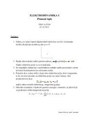
930 Chapter 28 Atomic <strong>Physics</strong>Emitter Base Collector–++–∆V eb+ –p––––+ +n+ ++ ++ +––––pEmitterCollectorI bI bbep n pI eI ccR(a)(b)Base+ –∆V ec(c)Figure 28.31 (a) The pnp transistor consists of an n region (base) sandwiched between twop regions (emitter and collector). (b) Circuit symbol for the pnp transistor. (c) A bias voltage V ebapplied to the base as shown produces a small base current I b that is used to control the collectorcurrent I c in a pnp transistor.Suppose a voltage is applied to the transistor so that the emitter is at a higherelectric potential than the collector. (This is accomplished with the battery labeledV ec in Figure 28.31c.) If we think of the transistor as two diodes back to back, wesee that the emitter–base junction is forward biased and the base–collector junctionis reverse biased. The emitter is heavily doped relative to the base, and as a result,nearly all the current consists of holes moving across the emitter–base junction.Most of these holes do not recombine with electrons in the base because it isvery narrow. Instead they are accelerated across the reverse-biased base–collectorjunction, producing the emitter current I e in Figure 28.31c.Although only a small percentage of holes recombine in the base, those that dolimit the emitter current to a small value because positive charge carriers accumulatingin the base prevent holes from flowing in. In order not to limit the emittercurrent, some of the positive charge on the base must be drawn off; this is accomplishedby connecting the base to the battery labeled V eb in Figure 28.31c. Thosepositive charges that are not swept across the base–collector junction leave thebase through this added pathway. This base current I b is very small, but a smallchange in it can significantly change the collector current I c . If the transistor isproperly biased, the collector (output) current is directly proportional to the base(input) current and the transistor acts as a current amplifier. This condition maybe writtenI c I bwhere , the current gain factor, is typically in the range from 10 to 100. Thus, thetransistor may be used to amplify a small signal. The small voltage to be amplifiedis placed in series with the battery V eb . The input signal produces a small variationin the base current, resulting in a large change in the collector current and hencea large change in the voltage across the output resistor.The Integrated CircuitInvented independently by Jack Kilby (b. 1923) at Texas Instruments in late 1958and by Robert Noyce at Fairchild Camera and Instrument in early 1959, the integratedcircuit has been justly called “the most remarkable technology ever to hitmankind.” Kilby’s first device is shown in Figure 28.32a. Integrated circuits have indeedstarted a “second industrial revolution” and are found at the heart of computers,watches, cameras, automobiles, aircraft, robots, space vehicles, and all sortsof communication and switching networks.In simplest terms, an integrated circuit is a collection of interconnected transistors,diodes, resistors, and capacitors fabricated on a single piece of siliconknown as a chip. State-of-the-art chips easily contain several million components in
- Page 1 and 2:
Color-enhanced scanning electronmic
- Page 3:
876 Chapter 27 Quantum PhysicsSolve
- Page 6 and 7: 27.2 The Photoelectric Effect and t
- Page 8 and 9: 27.3 X-Rays 881even when black card
- Page 10 and 11: 27.4 Diffraction of X-Rays by Cryst
- Page 12 and 13: 27.5 The Compton Effect 885Exercise
- Page 14 and 15: 27.6 The Dual Nature of Light and M
- Page 16 and 17: 27.6 The Dual Nature of Light and M
- Page 18 and 19: 27.8 The Uncertainty Principle 891w
- Page 20 and 21: 27.8 The Uncertainty Principle 893E
- Page 22 and 23: 27.9 The Scanning Tunneling Microsc
- Page 24 and 25: Problems 897The probability per uni
- Page 26 and 27: Problems 89917. When light of wavel
- Page 28 and 29: Problems 90151.time of 5.00 ms. Fin
- Page 30 and 31: “Neon lights,” commonly used in
- Page 32 and 33: 28.2 Atomic Spectra 905l(nm) 400 50
- Page 34 and 35: 28.3 The Bohr Theory of Hydrogen 90
- Page 36 and 37: 28.3 Th Bohr Theory of Hydrogen 909
- Page 38 and 39: 28.4 Modification of the Bohr Theor
- Page 40 and 41: 28.6 Quantum Mechanics and the Hydr
- Page 42 and 43: 28.7 The Spin Magnetic Quantum Numb
- Page 44 and 45: 28.9 The Exclusion Principle and th
- Page 46 and 47: 28.9 The Exclusion Principle and th
- Page 48 and 49: 28.11 Atomic Transitions 921electro
- Page 50 and 51: 28.12 Lasers and Holography 923is u
- Page 52 and 53: 28.13 Energy Bands in Solids 925Ene
- Page 54 and 55: 28.13 Energy Bands in Solids 927Ene
- Page 58 and 59: Summary 931(a)Figure 28.32 (a) Jack
- Page 60 and 61: Problems 9335. Is it possible for a
- Page 62 and 63: Problems 935tum number n. (e) Shoul
- Page 64 and 65: Problems 93748. A dimensionless num
- Page 66 and 67: Aerial view of a nuclear power plan
- Page 68 and 69: 29.1 Some Properties of Nuclei 941T
- Page 70 and 71: 29.2 Binding Energy 943130120110100
- Page 72 and 73: 29.3 Radioactivity 94529.3 RADIOACT
- Page 74 and 75: 29.3 Radioactivity 947INTERACTIVE E
- Page 76 and 77: 29.4 The Decay Processes 949Alpha D
- Page 78 and 79: 29.4 The Decay Processes 951Strateg
- Page 80 and 81: 29.4 The Decay Processes 953they we
- Page 82 and 83: 29.6 Nuclear Reactions 955wounds on
- Page 84 and 85: 29.6 Nuclear Reactions 957EXAMPLE 2
- Page 86 and 87: 29.7 Medical Applications of Radiat
- Page 88 and 89: 29.7 Medical Applications of Radiat
- Page 90 and 91: 29.8 Radiation Detectors 963Figure
- Page 92 and 93: Summary 965Photo Researchers, Inc./
- Page 94 and 95: Problems 967CONCEPTUAL QUESTIONS1.
- Page 96 and 97: Problems 96924. A building has beco
- Page 98 and 99: Problems 97157. A by-product of som
- Page 100 and 101: This photo shows scientist MelissaD
- Page 102 and 103: 30.1 Nuclear Fission 975Applying Ph
- Page 104 and 105: 30.2 Nuclear Reactors 977Courtesy o
- Page 106 and 107:
30.2 Nuclear Reactors 979events in
- Page 108 and 109:
30.3 Nuclear Fusion 981followed by
- Page 110 and 111:
30.3 Nuclear Fusion 983VacuumCurren
- Page 112 and 113:
30.6 Positrons and Other Antipartic
- Page 114 and 115:
30.7 Mesons and the Beginning of Pa
- Page 116 and 117:
30.9 Conservation Laws 989LeptonsLe
- Page 118 and 119:
30.10 Strange Particles and Strange
- Page 120 and 121:
30.12 Quarks 993n pΣ _ Σ 0 Σ + S
- Page 122 and 123:
30.12 Quarks 995charm C 1, its anti
- Page 124 and 125:
30.14 Electroweak Theory and the St
- Page 126 and 127:
30.15 The Cosmic Connection 999prot
- Page 128 and 129:
30.16 Problems and Perspectives 100
- Page 130 and 131:
Problems 100330.12 Quarks &30.13 Co
- Page 132 and 133:
Problems 1005particles fuse to prod
- Page 134 and 135:
Problems 100740. Assume binding ene
- Page 136 and 137:
A.1 MATHEMATICAL NOTATIONMany mathe
- Page 138 and 139:
A.3 Algebra A.3by 8, we have8x8 32
- Page 140 and 141:
A.3 Algebra A.5EXERCISESSolve the f
- Page 142 and 143:
A.5 Trigonometry A.7When natural lo
- Page 144 and 145:
APPENDIX BAn Abbreviated Table of I
- Page 146 and 147:
An Abbreviated Table of Isotopes A.
- Page 148 and 149:
An Abbreviated Table of Isotopes A.
- Page 150 and 151:
Some Useful Tables A.15TABLE C.3The
- Page 152 and 153:
Answers to Quick Quizzes,Odd-Number
- Page 154 and 155:
Answers to Quick Quizzes, Odd-Numbe
- Page 156 and 157:
Answers to Quick Quizzes, Odd-Numbe
- Page 158 and 159:
Answers to Quick Quizzes, Odd-Numbe
- Page 160 and 161:
Answers to Quick Quizzes, Odd-Numbe
- Page 162 and 163:
Answers to Quick Quizzes, Odd-Numbe
- Page 164 and 165:
Answers to Quick Quizzes, Odd-Numbe
- Page 166 and 167:
Answers to Quick Quizzes, Odd-Numbe
- Page 168 and 169:
IndexPage numbers followed by “f
- Page 170 and 171:
Current, 568-573, 586direction of,
- Page 172 and 173:
Index I.5Fissionnuclear, 973-976, 9
- Page 174 and 175:
Index I.7Magnetic field(s) (Continu
- Page 176 and 177:
Polarizer, 805-806, 805f, 806-807Po
- Page 178 and 179:
South poleEarth’s geographic, 626
- Page 180 and 181:
CreditsPhotographsThis page constit
- Page 182 and 183:
PEDAGOGICAL USE OF COLORDisplacemen
- Page 184 and 185:
PHYSICAL CONSTANTSQuantity Symbol V