

Square Air Core RF Inductors - AVX
Square Air Core RF Inductors - AVX
Square Air Core RF Inductors - AVX

Create successful ePaper yourself
Turn your PDF publications into a flip-book with our unique Google optimized e-Paper software.
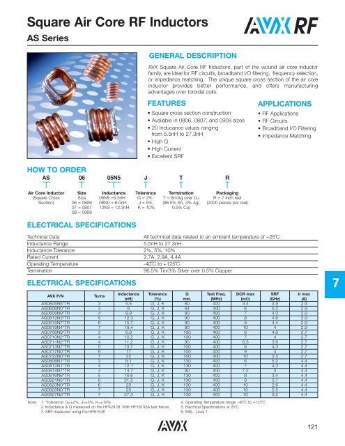
<strong>Square</strong> <strong>Air</strong> <strong>Core</strong> <strong>RF</strong> <strong>Inductors</strong>AS SeriesGENERAL DESCRIPTION<strong>AVX</strong> <strong>Square</strong> <strong>Air</strong> <strong>Core</strong> <strong>RF</strong> <strong>Inductors</strong>, part of the wound air core inductorfamily, are ideal for <strong>RF</strong> circuits, broadband I/O filtering, frequency selection,or impedance matching. The unique square cross section of the air coreinductor provides better performance, and offers manufacturingadvantages over toroidal coils.FEATURES• <strong>Square</strong> cross section construction• Available in 0806, 0807, and 0908 sizes• 20 Inducance values rangingfrom 5.5nH to 27.3nH• High Q• High Current• Excellent S<strong>RF</strong>APPLICATIONS• <strong>RF</strong> Applications• <strong>RF</strong> Circuits• Broadband I/O Filtering• Impedance MatchingHOW TO ORDERAS0605N5JTR<strong>Air</strong> <strong>Core</strong> Inductor(<strong>Square</strong> CrossSection)SizeSize06 = 080607 = 080708 = 0908Inductance05N5 =5.5nH06N0 = 6.0nH12N3 = 12.3nHToleranceG = 2%J = 5%K = 10%TerminationT = Sn/Ag over Cu(96.5% Sn, 3% Ag,0.5% Cu)PackagingR = 7 inch reel(2000 pieces per reel)ELECTRICAL SPECIFICATIONSTechnical DataAll technical data related to an ambient temperature of +25˚CInductance Range5.5nH to 27.3nHInductance Tolerance 2%, 5%, 10%Rated Current 2.7A, 2.9A, 4.4AOperating Temperature-40˚C to +125˚CTermination96.5% Tin/3% Silver over 0.5% CopperELECTRICAL SPECIFICATIONSNote:<strong>AVX</strong> P/NTurnsInductance Tolerance Q Test Freq. DCR max S<strong>RF</strong> Ir max(nH) (%) min. (MHz) (mΩ) (GHz) (A)AS0605N5*TR 3 5.5 G, J, K 60 400 3.4 4.9 2.9AS0606N0*TR 3 6 G, J, K 64 400 6 5.2 2.9AS0608N9*TR 4 8.9 G, J, K 90 400 7 4.3 2.9AS0612N3*TR 5 12.3 G, J, K 90 400 8 4.8 2.9AS0615N7*TR 6 15.7 G, J, K 90 400 9 4.4 2.9AS0619N4*TR 7 19.4 G, J, K 90 400 10 4 2.9AS0706N9*TR 3 6.9 G, J, K 100 400 6 4.6 2.7AS0710N2*TR 4 10.2 G, J, K 100 400 7 4 2.7AS0711N2*TR 4 11.2 G, J, K 90 400 6.3 3.6 2.7AS0713N7*TR 5 13.7 G, J, K 100 400 8 4.3 2.7AS0717N0*TR 6 17 G, J, K 100 400 9 4 2.7AS0722N0*TR 7 22 G, J, K 100 400 10 3.5 2.7AS0808N1*TR 3 8.1 G, J, K 130 400 6 5.2 4.4AS0812N1*TR 4 12.1 G, J, K 130 400 7 4.3 4.4AS0814N7*TR 4 14.7 G, J, K 90 400 7.2 3 4.4AS0816N6*TR 5 16.6 G, J, K 130 400 8 3.4 4.4AS0821N5*TR 6 21.5 G, J, K 130 400 9 3.7 4.4AS0823N0*TR 6 23 G, J, K 130 400 10 2.6 4.4AS0825N0*TR 7 25 G, J, K 130 400 10 2.5 4.4AS0827N3*TR 7 27.3 G, J, K 130 400 10 3.2 4.41. *Tolerance: G=±2%, J=±5%, K=±10%2. Inductance & Q measured on the HP4291B. With HP16193A test fixture.3. S<strong>RF</strong> measured using the HP8753E4. Operating Temperature range: -40˚C to +125˚C5. Electrical Specifications at 25˚C6. MSL: Level 17121
<strong>Square</strong> <strong>Air</strong> <strong>Core</strong> <strong>RF</strong> <strong>Inductors</strong>AS SeriesPHYSICAL DIMENSIONSADMAX.MIN.CEBF7mm (inches)Part Number A B C D E FAS0605N5*TR1.346±0.102 1.829±0.254 1.397±0.102 0.962 2.60 0.51(0.053±0.004) (0.072±0.01) (0.055±0.004) (0.038) (0.102) (0.020)AS0606N0*TR1.295±0.102 1.829±0.254 1.397±0.102 0.99 2.60 0.51(0.051±0.004) (0.072±0.01) (0.055±0.004) (0.390) (0.102) (0.020)AS0608N9*TR1.626±0.152 1.829±0.254 1.397±0.102 1.27 2.60 0.51(0.640±0.006) (0.072±0.01) (0.055±0.004) (0.050) (0.102) (0.020)AS0612N3*TR1.930±0.152 1.829±0.254 1.397±0.102 1.63 2.60 0.51(0.076±0.006) (0.072±0.01) (0.055±0.004) (0.064) (0.102) (0.020)AS0615N7*TR2.286±0.152 1.829±0.254 1.397±0.102 1.96 2.60 0.51(0.09±0.006) (0.072±0.01) (0.055±0.004) (0.070) (0.102) (0.020)AS0619N4*TR2.591±0.152 1.829±0.254 1.397±0.102 2.29 2.60 0.51(0.102±0.006) (0.072±0.01) (0.055±0.004) (0.090) (0.102) (0.020)AS0706N9*TR1.295±0.102 1.829±0.254 1.524±0.254 1.02 2.60 0.51(0.051±0.004) (0.072±0.01) (0.060±0.010) (0.040) (0.102) (0.020)AS0710N2*TR1.626±0.152 1.829±0.254 1.524±0.254 1.32 2.60 0.51(0.064±0.006) (0.072±0.01) (0.060±0.010) (0.052) (0.102) (0.020)AS0711N2*TR1.549±0.152 1.829±0.254 1.524±0.254 1.24 2.60 0.51(0.061±0.006) (0.072±0.01) (0.060±0.010) (0.049) (0.102) (0.020)AS0713N7*TR1.930±0.152 1.829±0.254 1.524±0.254 1.57 2.60 0.51(0.076±0.006) (0.072±0.01) (0.060±0.010) (0.062) (0.102) (0.020)AS0717N0*TR2.286±0.152 1.829±0.254 1.524±0.254 1.93 2.60 0.51(0.09±0.006) (0.072±0.01) (0.060±0.010) (0.076) (0.102) (0.020)AS0722N0*TR2.591±0.152 1.829±0.254 1.524±0.254 2.29 2.60 0.51(0.102±0.006) (0.072±0.01) (0.060±0.010) (0.090) (0.102) (0.020)AS0808N1*TR1.473±0.152 2.134±0.152 1.829±0.152 1.12 2.80 0.64(0.058±0.006) (0.084±0.006) (0.072±0.006) (0.044) (0.110) (0.025)AS0812N0*TR1.854±0.152 2.134±0.152 1.829±0.152 1.45 2.80 0.64(0.073±0.006) (0.084±0.006) (0.072±0.006) (0.570) (0.110) (0.025)AS0814N7*TR1.549±0.152 2.134±0.152 1.829±0.152 1.24 2.80 0.64(0.061±0.006) (0.084±0.006) (0.072±0.006) (0.049) (0.110) (0.025)AS0816N6*TR2.210±0.152 2.134±0.152 1.829±0.152 1.83 2.80 0.64(0.087±0.006) (0.084±0.006) (0.072±0.006) (0.072) (0.110) (0.025)AS0821N5*TR2.565±0.152 2.134±0.152 1.829±0.152 2.18 2.80 0.64(0.101±0.006) (0.084±0.006) (0.072±0.006) (0.086) (0.110) (0.025)AS0823N0*TR2.235±0.152 2.134±0.152 1.829±0.152 1.90 2.80 0.64(0.088±0.006) (0.084±0.006) (0.072±0.006) (0.075) (0.110) (0.025)AS0825N0*TR2.972±0.152 2.134±0.152 1.829±0.152 2.57 2.80 0.64(0.117±0.006) (0.084±0.006) (0.072±0.006) (0.101) (0.110) (0.025)AS0827N3*TR2.972±0.152 2.134±0.152 1.829±0.152 2.57 2.80 0.64(0.117±0.006) (0.084±0.006) (0.072±0.006) (0.101) (0.110) (0.025)122
<strong>Square</strong> <strong>Air</strong> <strong>Core</strong> <strong>RF</strong> <strong>Inductors</strong>AS SeriesPE<strong>RF</strong>ORMANCE SPECIFICATIONSAS06Inductance vs. FrequencyTypical Q vs. Frequency30160Inductance (nH)252015105Q1401201008060402019N415N708N905N5010 100 1000 10000010 100 1000 10000Frequency (MHz)Frequency (MHz)AS07Inductance vs. FrequencyTypical Q vs. Frequency3025025200Inductance (nH)2015105Q1501005022N017N011N206N9010 100 1000 10000010 100 1000 10000Frequency (MHz)Frequency (MHz)AS087Inductance vs. FrequencyTypical Q vs. FrequencyInductance (nH)8075706560555045403530252015105010 100 1000 10000Q50045040035030025020015010050010 100 1000 1000027N316N612N108N1Frequency (MHz)Frequency (MHz)123
<strong>Square</strong> <strong>Air</strong> <strong>Core</strong> <strong>RF</strong> <strong>Inductors</strong>AS SeriesTYPICAL RoHS REFLOW PROFILE300250Time within 5ºCof peak temperature(30 seconds)Temperature (ºC)217200150100Preheat / Soak(60–120 seconds)Ramp-Up3ºC/sec maxReflowTime above 217ºC(60–150 seconds)Ramp-Down6ºC/sec maxPeak Temperature255–260ºC5000 30 60 90 120 150 180 210 240 270 300Time (seconds)7124
<strong>Square</strong> <strong>Air</strong> <strong>Core</strong> <strong>RF</strong> <strong>Inductors</strong>AS SeriesPACKAGING SPECIFICATIONSThickness (t)0.10 (.004) maxEmbossed Cavity• The force for tearing off cover tape is10 to 130 grams in the arrow directionTop Cover Tape165° to 180°Embossed CarrierBase TapeEndStartNo Components Components160 (6.299) minCover TapeUser Direction of FeedNo Components390 (15.354) min560 (22.047) maxCARRIER TAPE REELSGDIMENSIONS OF CARRIER TAPED0P2P0Et7A BNCFW5°CETITEM A B C G N T W E F P1 P2 P0 D0 D1 tDIM.178 25 15 12.5 75 16.4 12.0 1.75 5.50 4.00 2.0 4.0 1.5 1.0 0.23(7.008) (0.984) (0.591) (0.492) (2.953) (0.646) (0.472) (0.069) (0.217) (0.157) (0.079) (0.157) (0.059) (0.039) (0.009)±2.0 ±1.0 ±0.5 +1.5 ±2.0 +1.5 ±0.2 ±0.1 ±0.1 ±0.1 ±0.1 ±0.1 +0.1 ±0.1 ±0.05TOL.(0.079) (0.039) (0.020) (0.059) (0.079) (0.059) (0.008) (0.004) (0.004) (0.004) (0.004) (0.004) (0.004) (0.004) (0.020)D1P1mm (inches)125


