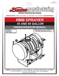
AS20001 - 55 Gallon Sprayer Operators Manual - Demco Products
AS20001 - 55 Gallon Sprayer Operators Manual - Demco Products
AS20001 - 55 Gallon Sprayer Operators Manual - Demco Products

Create successful ePaper yourself
Turn your PDF publications into a flip-book with our unique Google optimized e-Paper software.
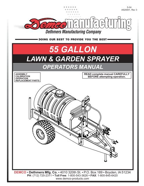
5-04<strong>AS20001</strong>, Rev 3DOING OUR BEST TO PROVIDE YOU THE BEST<strong>55</strong> GALLONLAWN & GARDEN SPRAYERASSEMBLYCALIBRATIONOPERATIONREPLACEMENT PARTSOPERATORS MANUALREAD complete manual CAREFULLYBEFORE attempting operation.DEMCO • Dethmers Mfg. Co. • 4010 320th St. • P.O. Box 189 • Boyden, IA 51234PH: (712) 725-2311 • Toll Free: 1-800-543-3626 • FAX: 1-800-845-6420www.demco-products.comPage 1
Thank you for purchasing a <strong>Demco</strong> sprayer. We feel you have made a wise choice and hope you arecompletely satisfied with your new sprayer. If you have any questions regarding the applications ofcertain solutions or chemicals, contact your chemical supplier and follow chemical manufacturerrecommendations as well as all licensing and use restrictions or regulations.WARNINGTo prevent serious injury or deathï Refer to chemical supplier and manufacturer recommendations and alllicensing restrictions or regulations.ï Always wear recommended protective clothing when working with chemicals orsprayer.ï Dispose of all unused chemicals or solutions in proper and ecologically sound manner.Improper use can injure people, animals, plants and soil.GENERAL INFORMATION1. Unless otherwise specified, high-strength (grade5)(3 radial-line head markings) hex head bolts areused throughout assembly of this sprayer.3. When placing a parts order, refer to this manual forproper part numbers and place order by PART NO.,DESCRIPTION, and COLOR.2. Whenever terms "LEFT" and "RIGHT" are used inthis manual it means from a position behind sprayerand facing forward.Table of ContentsGeneral information ..............................................................................................................................2Safety Sign Locations ..........................................................................................................................3Bolt Torque ...........................................................................................................................................4Skid Mount with the Trailer Kit Parts Breakdown and Parts List ............................................................51.5 <strong>Gallon</strong> Electric Pump Plumbing Parts Breakdown and Parts List .............................................. 65 <strong>Gallon</strong> Electric Pump Plumbing Parts Breakdown and Parts List ................................................. 7PTO Roller Pump Plumbing Parts Breakdown and Parts List .......................................................... 8Gas Engine Roller Pump Plumbing Parts Breakdown and Parts List ............................................ 9-10Gas Engine Diaphragm Pump Plumbing Parts Breakdown and Parts List ................................... 10-11Gas Engine Diaphragm Pump Operation and Maintenance Instructions ....................................... 12Gas Engine Piston Pump Plumbing Parts Breakdown and Parts List ............................................. 1380” Boom Parts Breakdown and Parts List ...................................................................................... 1412’ and 18’ Boom Parts Breakdown and Parts List ......................................................................... 151.5 G.P.M. Electric Pump Parts Breakdown and Parts List ............................................................... 165 G.P.M. Electric Pump Parts Breakdown and Parts List .................................................................. 16C4101 & XL4101 Pump Parts Breakdown and Parts List ............................................................... 17C6500D & XL6500 Pump Parts Breakdown and Parts List ............................................................. 18Piston Pump Parts Breakdown and Parts List ................................................................................. 19Diaphragm Pump Parts Breakdown and Parts List ......................................................................... 20Spray Wand Parts Breakdown and Parts List .................................................................................. 21Bypass Valve Parts Breakdown and Parts List ................................................................................. 22Single Section Valve Parts Breakdown and Parts List ..................................................................... 22<strong>Sprayer</strong> Calibration .......................................................................................................................... 23<strong>Sprayer</strong> Checklist ...............................................................................................................................24Page 2
SAFETY SIGN LOCATIONSTypes of safety sign and locations on equipment are shown in illustration below. Good safetyrequires that you familiarize yourself with various safety signs, type of warning, and area orparticular function related to that area, that requires your SAFETY AWARENESS.BABA. AB21014 - Warning: Refer to chemicalsupplier and manufacturer Qty. 1WARNINGTo prevent serious injury or death• Refer to chemical supplier and manufacturer recommendations and alllicensing restrictions or regulations.• Always wear recommended protective clothing when working with chemicals orsprayer.• Dispose of all unused chemicals or solutions in proper and ecologicallysound manner. Improper use can injure people, animals, plants and soil.01/00 AB21014B. AA21012 - Small <strong>Demco</strong> Qty. 2Page 3
BOLT TORQUETORQUE DATA FOR STANDARD NUTS, BOLTS, AND CAPSCREWS.Tighten all bolts to torques specified in chart unless otherwise noted. Check tightness ofbolts periodically, using bolt chart as guide. Replace hardware with same grade bolt.NOTE: Unless otherwise specified, high-strength Grade 5 hex bolts are used throughoutassembly of equipment.Bolt Torque for Standard bolts *Torque SpecificationsGRADE 2 GRADE 5 GRADE 8“A” lb-ft (N.m) lb-ft (N.m) lb-ft (N.m)1/4” 6 (8) 9 (12) 12 (16)5/16” 10 (13) 18 (25) 25 (35)3/8” 20 (27) 30 (40) 45 (60)7/16” 30 (40) 50 (70) 80 (110)1/2” 45 (60) 75 (100) 115 (1<strong>55</strong>)9/16” 70 (95) 115 (1<strong>55</strong>) 165 (220)5/8” 95 (130) 150 (200) 225 (300)3/4” 165 (225) 290 (390) 400 (540)7/8” 170 (230) 420 (570) 650 (880)1” 225 (300) 630 (850) 970 (1310)Bolt Torque for Metric bolts *Torque figures indicated are valid fornon-greased or non-oiled threads andheads unless otherwise specified.Therefore, do not grease or oil bolts orcapscrews unless otherwise specifiedin this manual. When using lockingelements, increase torque valuesby 5%.* GRADE or CLASS value for boltsand capscrews are identified by theirhead markings.CLASS 8.8 CLASS 9.8 CLASS 10.9“A” lb-ft (N.m) lb-ft (N.m) lb-ft (N.m)6 9 (13) 10 (14) 13 (17)7 15 (21) 18 (24) 21 (29)8 23 (31) 25 (34) 31 (42)10 45 (61) 50 (68) 61 (83)12 78 (106) 88 (118) 106 (144)14 125 (169) 140 (189) 170 (230)16 194 (263) 216 (293) 263 (357)18 268 (363) -- -- 364 (493)20 378 (513) -- -- 515 (689)22 516 (699) -- -- 702 (952)24 654 (886) -- -- 890 (1206)GRADE-2 GRADE-5 GRADE-8CLASS 8.8 CLASS 9.8 CLASS 10.98.8 9.8 10.9Page 4
<strong>55</strong> GALLON SKID MOUNT SPRAYER WITH TR<strong>55</strong>CB (TRAILER KIT)181341758147722426111292996167131972871910972620277192221792523REF.NO.PARTNO.QTY.REQD DESCRIPTION- 5316 2 50" Strap Assembly1. 00004 2 5/16î Flatwasher2. 02802 2 5/16"-18 UNC Nylon Insert Locknut3. 04352 2 5/16"-18 UNC x 4" F.T. Hex Hd. Bolt4. 04353 - 50" Nylon Strap Black5. 05785-95 2 Small Strap Anchor - 1-3/4" Strap6. 00214 4 1/4” Flatwasher7. 00907 8 3/8"-16 UNC x 1" Hex Head Bolt8. 009<strong>55</strong> 2 1/4"-20 UNC x 1" Round U-Bolt9. 02592 12 3/8"-16 UNC Nylon Insert Locknut10. 02625-10 1 Trailer Main Frame11. 02630-10 1 Right Hose Storage Bracket12. 02631-10 1 Left Hose Storage Bracket13. 02632-10 1 Control Valve Mount14. 02633-10 1 Right Boom Mount15. 02634-10 1 Left Boom Mount (not shown)16. 02772 4 1/4"-20 UNC Nylon Insert Locknut17. P<strong>55</strong> 23 1 <strong>55</strong> gal. Poly Tank- P<strong>55</strong> 23A 1 <strong>55</strong> gal. Poly Tank w/ Agitation Installed18. PL5A 1 5" dia. Lid w/ O-ring20. 00095 1 3/8-16 UNC x 3/4" Sq. Hd. Set Screw29. 02529 2 3/8”-16 UNC x 2-1/2” Round U-Bolt<strong>55</strong> GALLON SPRAYER FRAME PARTS LISTPage 5REF.NO.PARTNO.QTY.REQD DESCRIPTION- TR<strong>55</strong>CB - <strong>55</strong> <strong>Gallon</strong> Trailer Kit19. 00059 8 3/8" Flatwasher20. 00095 4 3/8-16 UNC x 3/4" Sq. Hd. Set Screw7. 00907 14 3/8"-16 UNC x 1" Hex Head Bolt21. 01404-95 1 Lock Handle9. 02592 14 3/8"-16 UNC Nylon Insert Locknut22. 02626-10 1 Tongue23. 02627-10 1 Clevis Hitch24. 02628-10 1 Axle25. 02629-10 1 Safety Stand26. 02635-95 4 Wheel Space Collar27. TW18X8 2 18" x 9-1/2” x 8", 2 ply High FlotationTire and Hub- 02642 1 Bearing (only)- 02643 2 Retainer (only)28. 02669-10 1 Valve Mount (red)Please order replacement parts by PART NO., COLOR, andDESCRIPTION.
1.5 GALLON ELECTRIC PUMP PLUMBING PARTS BREAKDOWN3322 231314162523122319302031341832212323144231729232162627247 923112 5 118105353285REF.NO.PARTNO.QTY.REQD DESCRIPTION1. 00214 6 1/4" Flatwasher2. 00336 4 1/4"-20 UNC x 1-1/4" Hex Head Bolt3. 00907 1 3/8"-16 UNC x 1" Hex Head Bolt4. 009<strong>55</strong> 1 1/4"-20 UNC x 2" Rd. U-bolt5. 02772 7 1/4"-20 UNC Nylon Insert Locknut6. 03900 1 3/8" FPT x 3/8" FPT Valve7. 040<strong>55</strong> 1 1/4"-20UNC x 1" Hex Head Bolt8. 047<strong>55</strong>-95 1 Switch Mount9. 04764 1 10’ Wire Harness10. 05020 2 Male Bullet Connector11. 05021 2 Female Bullet Connector12. 120RB - 1/2" I.D Rubber Hose13. 30L 22425 18 1 18" Hand Spray Wand14. 380RB - 3/8" I.D. Rubber Hose16. <strong>55</strong>00 6PP 1 Adjustable Tip17. 60GB 1 60 lb. Pressure Gauge18. 8000 543 150 1 12 Volt Electric Pump19. 8027 1 Swivel Nut20. 8079NY 1 50 Mesh Poly Strainer21. A1238 1 1/2" MPT x 3/8" Hose BarbPUMP PLUMBING PARTS LISTREF.NO.PARTNO.QTY.REQD DESCRIPTION22. A1438 1 1/4" MPT x 3/8" Hose Barb Fitting23. B6H 8 3/8" Hose Clamp SS24. BEL1212 1 1/2" MPT x 1/2" Hose Barb Elbow25. BEL3412 1 3/4" MPT x 1/2" Hose Barb Elbow26. BM1238 1 1/2" MPT x 3/8" Reducer Nipple27. BTT12G 1 1/2" FPT Tee (Tapped for Gauge)28. EL3812 1 3/8" MPT x 1/2" Hose Barb Elbow29. EL3838 1 3/8" MPT x 3/8" Hose Barb Elbow30. K8400 1/2 1 1/2" Hose Barb31. NB1614 1 1/4" MPT x11/16" MPT Strainer Fitting32. P<strong>55</strong> 23 1 <strong>55</strong> <strong>Gallon</strong> Poly Tank33. PL5A 1 5" dia. Lid w/ O-ring34. RB3814 1 3/8" MPT x 1/4" FPT Reducer Fitting35. 05004 2 Female Push on Connector (connects toback of toggle switch)Please order replacement parts by PART NO. and DESCRIPTION.Page 6
5 GALLON ELECTRIC PUMP PLUMBING PARTS BREAKDOWN34162120172132262414213521 29232812625182715930 31 221472121 23211a 3614b225d22118211113333212314417105NOTE: Use thread sealanton all threaded fittings.5REF.NO.PARTNO.QTY.REQD DESCRIPTION1. 00214 6 1/4" Flatwasher2. 00336 4 1/4"-20 UNC x 1-1/4" Hex Head Bolt3. 00907 1 3/8"-16 UNC x 1" Hex Head Bolt4. 009<strong>55</strong> 1 1/4"-20 UNC x 2" Rd. U-bolt5. 02772 7 1/4"-20 UNC Nylon Insert Locknut6. 03900 1 3/8" FPT x 3/8" FPT Valve7. 040<strong>55</strong> 1 1/4"-20UNC x 1" Hex Head Bolt8. 047<strong>55</strong>-95 1 Switch Mount9. 04764 1 10’ Wire Harness10. 05020 2 Male Bullet Connector11. 05021 2 Female Bullet Connector12. 100GB 1 100 lb. Brass Pressure Gauge13. 10983 1 Electric 12 VDC Pump (5 GPM)14. 120RB - 1/2" I.D Rubber Hose15. 23120PP 1 1/2" NPT Pressure Relief Valve16. 30L-18PP 1 18" Hand Spray Wand17. 380RB - 3/8" I.D. Rubber Hose18. 5044 1 1 Single Aggitation Wand Assembly20. A1438 1 1/4" MPT x 3/8" Hose Barb Fitting21. B6H 12 3/8" Hose Clamp SSPUMP PLUMBING PARTS LISTREF.NO.PARTNO.QTY.REQD DESCRIPTION22. BA1212 2 1/2" MPT x 3/8" Hose Barb23. BEL1212 3 1/2" MPT x 1/2" Hose Barb Elbow24. BEL3412 1 3/4" MPT x 1/2" Hose Barb Elbow25. BM1238 1 1/2" MPT x 3/8" MPT Reducer Nipple26. BRB114 34 1 1-1/4î MPT x 3/4î Reducer Fitting27. BTT12G 1 1/2" FPT Tee (Tapped for Gauge)28. EL1438 1 1/4" MPT x 3/8" Hose Barb Elbow29. EL3838 1 3/8" MPT x 3/8" Hose Barb Elbow30. M1200 1 1/2î MPT Nipple31. P012DSW 1 1/2î Double Thread Spin Weld Fitting32 P114PAVSW 1 1-1/4î Anti-Vortex Spin Weld Fitting33. P<strong>55</strong> 23A 1 <strong>55</strong>gal. Poly Tank34. PL5A 1 5" dia. Lid w/ O-ring35. RVB12 80 1 Strainer Assembly w/ 80 mesh screena. RVF38C 1 1/2” Strainer Cupb. RVB80 1 80 Mesh Screen for 1/2” Strainerc. RVB38GE 1 Viton 0-Ring (not shown)d. RVB38B 1 Strainer Bowl36. 05004 2 Female Push on Connector (connects toback of toggle switch)Page 7Please order replacement parts by PART NO. and DESCRIPTION.
(TR<strong>55</strong>RP) ROLLER PUMP PLUMBINGPARTS BREAKDOWN AND PARTS LIST20172428414018191828192825393326 32112282333348162621 3222182636442643374528152631 28 29 30393330343234 26323926 33 a 33b27 c 385 d693226103741318262 32128263235114R0LLER PUMP PLUMBING PARTS LISTREF.NO.PARTNO.QTY.REQD DESCRIPTION1. 00036 2 5/16" Lockwasher2. 00214 5 1/4" Flatwasher3. 00907 1 3/8”-16 UNC x 1” Hex Head Bolt4. 01076 1 1/4”-20 UNC x 3/4” Hex Head Bolt5. 02150-95 1 Tee Mounting Bracket6. 02592 1 3/8”-16 UNC Nylon Insert Locknut7. 02616-10 1 Vertical Strainer Mounting Bracket8. 02772 5 1/4"-20 UNC Nylon Insert Locknut9. 02802 1 5/16”-18 UNC Nylong Insert Locknut10. 02990 1 5/16”-18 UNC x 1” Hex Head Bolt11. 040<strong>55</strong> 4 1/4”-20 UNC x 1” Hex Head Bolt12. 04298-70 1 Pump Mounting Bracket13. 04299 1 Roller Pump Chain14. 04305 2 5/16"-18 UNC x 1/2" Hex Head Bolt15. 120RB - 1/2" I.D Rubber Hose16. 160GB 1 160 lb. Brass Pressure Gauge17. 30L22425 18 1 18" Hand Spray Gun18. 340RB - 3/4" I.D Rubber Hose19. 380RB - 3/8" I.D. Rubber Hose20. <strong>55</strong>00 18PP 1 Adjustable Spray Tip21. 6B1 1 Direct - o - valve22. 8460 1 3/4" MPT Pressure Relief Valve23. A1238 1 1/2" MPT x 3/8" Hose Barb24. A1438 1 1/4î MPT x 3/8” Hose Barb25. A3438 1 3/4" MPT x 3/8" Hose Barb26. B12H 10 3/4" Hose Clamp SS27. B24H 2 1-1/4” Hose Clamp SS28. B6H 6 3/8" Hose Clamp SS29. BA3412 1 3/4" MPT x 1/2" Hose Barb30. BA3434 2 3/4" MPT x 3/4" Hose Barb31. BEL1212 1 1/2" MPT x 1/2" Hose Barb Elbow32. BEL3434 7 3/4" MPT x 3/4" Hose Barb Elbow33. BM3400 5 3/4" MPT Nipple34. BTT34 3 3/4" FPT Tee35. C6500D 1 Cast Iron Roller Pump w/Quick Coupler- XL6500D - Silver Cast Roller Pump- 1321 0012 1 Quick Coupler Adapter (540 RPM)36. EL114 34 1 1-1/4" MPT x 3/4" Hose Barb Elbow37. M1200 1 1/2" MPT Short Nipple38. RVF34 80 1 3/4" Line Strainer w/80 mesh screena. RVF34C 1 3/4" Strainer Cupb. RVF34GV 1 Viton O-ring for 3/4" Strainerc. RVF380 1 80 Mesh Screen for 3/4" Strainerd. RVF34B 1 Strainer Bowl39. UV075FP 3 3/4" Poly Ball Valve40. P<strong>55</strong> 23A 1 <strong>55</strong> <strong>Gallon</strong> Poly Tank w/ Agitation Installed41. PL5A 1 5" dia. Lid w/ O-ring43. 5044 1 1 Single Agitation Wand Assembly44. P114PAVSW 1 1-1/4” Anti-Vortex Spin Weld Fitting45. P012DSW 1 1/2” Double Thread Spin Weld FitingPlease order replacement parts by PART NO. and DESCRIPTION.Page 8
ENGINE DRIVEN ROLLER PUMP PLUMBING PARTS BREAKDOWN414020172444362618264330NOTE: Use thread sealanton all threaded fittings.37453931 28A3026189261530abcd272719272518263033343818161911272 223923 21C33 3332263234 1882628131418322651032626 28352629D739301 30 1891233 344926 32B103OPERATING INSTRUCTIONS1. Fill the tank with water.2. Open the Ball valve (A) in the pump intake line.3. Open (counter clockwise) the pressure relief valve (B).4. Open the Tee valve (C) so that all the boom sections arespraying.5. Open the agitation valve (D).6. Start and run pump.7. Slowly close the pressure relief valve (B) until the desiredspraying pressure is reached with the boom spraying.8. If adequate spraying pressure cannot be reached, slowlyclose the agitation valve (D) until the desired sprayingpressure is reached.9. Check for leaks.Page 9
ENGINE DRIVEN ROLLER PUMP PLUMBING PARTS LISTREF.NO.PARTNO.QTY.REQD DESCRIPTION1. 00036 2 5/16" Lockwasher2. 00214 4 1/4" Flatwasher3. 00372 4 5/16"-18 UNC x 1-1/2" Hex Head Bolt4. 01872 2 Rubber Bumper5. 02653-70 1 Pump Drive Shaft Shield6. 02658-10 1 Engine Mounting Plate7. 02660-70 1 Pump Mounting Bracket8. 02772 4 1/4"-20 UNC Nylon Insert Locknut9. 02802 9 5/16”-18 UNC Nylon Insert Locknut10. 02990 5 5/16”-18 UNC x 1” Hex Head Bolt11. 040<strong>55</strong> 4 1/4”-20 UNC x 1” Hex Head Bolt12. 04305 2 5/16"-18 UNC x 1/2" Hex Head Bolt13. 04880-95 1 Pump Coupler14. 07174 4 Coupler Set Screws15. 120RB - 1/2" I.D Rubber Hose16. 160GB 1 160 lb. Brass Pressure Gauge17. 30L22425 18 1 18" Hand Spray Gun18. 340RB - 3/4" I.D Rubber Hose19. 380RB - 3/8" I.D. Rubber Hose20. <strong>55</strong>00 18PP 1 Adjustable Spray Tip21. 6B1 1 Direct - o - valve22. 8460 1 3/4" MPT Pressure Relief Valve23. A1238 1 1/2" MPT x 3/8" Hose Barb24. A1438 1 1/4” MPT x 3/8” Hose Barb25. A3438 1 3/4" MPT x 3/8" Hose BarbREF.NO.PARTNO.QTY.REQD DESCRIPTION26. B12H 12 3/4" Hose Clamp SS27. B6H 6 3/8" Hose Clamp SS28. GE3HP 1 3-1/2 H.P. Briggs Gas Engine- GH4HP - 4 H.P. Honda Gas Engine29. BA3412 1 3/4" MPT x 1/2" Hose Barb30. BA3434 6 3/4" MPT x 3/4" Hose Barb31. BEL1212 1 1/2" MPT x 1/2" Hose Barb Elbow32. BEL3434 5 3/4" MPT x 3/4" Hose Barb Elbow33. BM3400 4 3/4" MPT Nipple34. BTT34 3 3/4" FPT Tee35. C4101 1 Cast Iron Roller Pump- XL4101 1 Silver Cast Roller Pump36. EL114 34 1 1-1/4" MPT x 3/4" Hose Barb Elbow37. M1200 1 1/2" MPT Short Nipple38. RVF34 80 1 3/4" Line Strainer w/80 mesh screena. RVF34C 1 3/4" Strainer Cupb. RVF380 1 80 Mesh Screen for 3/4" Strainerc. RVF34GV 1 Viton O-ring for 3/4" Strainerd. RVF34B 1 Strainer Bowl39. UV075FP 3 3/4" Poly Ball Valve40. P<strong>55</strong> 23A 1 <strong>55</strong> <strong>Gallon</strong> Poly Tank w/ Agitation Installed41. PL5A 1 5" dia. Lid w/ O-ring43. 5044 1 1 Single Agitation Wand Assembly44. P114PAVSW 1 1-1/4” Anti-Vortex Spin Weld Fitting45. P012DSW 1 1/2” Double Thread Spin Weld FitingPlease order replacement parts by PART NO. and DESCRIPTION.DIAPHRAGM PUMP PLUMBING PARTS LISTREF.NO.PARTNO.QTY.REQD DESCRIPTIONREF.NO.PARTNO.QTY.REQD DESCRIPTION1. 00004 8 5/16" Flatwasher24. BEL3434 1 3/4" MPT x 3/4" Hose Barb Elbow2. 00214 4 1/4" Flatwasher25. BM3400 3 3/4" MPT Nipple3. 00372 4 5/16"-18 UNC x 1-1/2" Hex Head Bolt 26. BTT34 2 3/4" FPT Tee4. 02615-10 2 Diaphragm Pump Mounting Bracket 27. EL114 34 1 1-1/4" MPT x 3/4" Hose Barb Elbow5. 02772 4 1/4"-20 UNC Nylon Insert Locknut28. EL1238 1 1/2" MPT x 3/8" Hose Barb Fitting6. 02802 8 5/16”-18 UNC Nylong Insert Locknut 29. EL3438 1 3/4" MPT x 3/8" Hose Barb7. 02990 4 5/16”-18 UNC x 1” Hex Head Bolt30. EL3458 1 3/4" MPT x 5/8" Hose Barb8. 040<strong>55</strong> 4 1/4”-20 UNC x 1” Hex Head Bolt31. F3400 1 3/4” MPT Plug9. 160GBF 1 160 lb. Brass Pressure Gauge Liquid Filled 32. GE3HP 1 3-1/2 H.P. Briggs Gas Engine10. 30L22425 18 1 18" Hand Spray Gun- GH4HP - 4 H.P. Honda Gas Engine11. 340RB - 3/4" I.D Rubber Hose33. RVF34 80 1 3/4" Line Strainer w/80 mesh screen12. 380RB - 3/8" I.D. Rubber Hosea. RVF34C 1 3/4" Strainer Cup13. <strong>55</strong>00 18PP 1 Adjustable Spray Tipb. RVF380 1 80 Mesh Screen for 3/4" Strainer14. 580RB - 5/8” I.D. Rubber Hosec. RVF34GV 1 Viton O-ring for 3/4" Strainer15. 6B1 1 Direct - o - valved. RVF34B 1 Strainer Bowl16. 9910D19GRGI 1 Diaphragm Pump34. UV075FP 3 3/4" Poly Ball Valve17. A1238 1 1/2" MPT x 3/8" Hose Barb35. P<strong>55</strong> 23A 1 <strong>55</strong> <strong>Gallon</strong> Poly Tank w/ Agitation Installed18. A1438 1 1/4” MPT x 3/8” Hose Barb36. PL5A 1 5" dia. Lid w/ O-ring19. A3438 3 3/4" MPT x 3/8" Hose Barb38. 5044 1 1 Single Agitation Wand Assembly20. B12H 6 3/4" Hose Clamp SS39. P114PAVSW 1 1-1/4” Anti-Vortex Spin Weld Fitting21. B6H 10 3/8" Hose Clamp SS40. P012DSW 1 1/2” Double Thread Spin Weld Fiting22. B8H 2 1/2” Hose Clamp SS41. M1200 1 1/2” MPT Short Nipple23. BA3434 3 3/4" MPT x 3/4" Hose Barb Please order replacement parts by PART NO. and DESCRIPTION.Page 10
ENGINE DRIVEN DIAPHRAGM PUMP PARTS BREAKDOWN36NOTE: Use thread sealanton all threaded fittings.35131018272039112021213841121240 12211921 2821 191734212521193423 23 253426201221 2930111220 23a 25 2214b982311<strong>55</strong>1632cd263320241121202236211247161Page 11
DIAPHRAGM PUMP INSTRUCTIONSOPERATION INSTRUCTIONS1. Be sure oil is halfway up the clear oil sight tube. Ifnecessary, fill to correct level with 30 weight nondetergentmotor oil.2. Make sure the suction hose barb is tightly screwed ontothe suction union, and that there are no air leaks on theinlet side of the pump.3. Check the charge pressure on the pulsation damperbefore starting the pump. The pressure is checked witha standard automotive air gauge. The pressure shouldbe at approximately 20% of the maximum operatingpressure with a minimum charge of 10 PSI.4. Allow the pump to start under low pressure by removingrestrictions on the outlet of the pump. The restriction onthe pump is removed by rotating the red knob on thecontrol unit so that the letter A on the knob is in the 12o'clock position.5. Start pump and let run for approximately one minute atlow pressure. Stop pump and check the oil level in sightglass. Add 30 weight non-detergent oil if necessary.6. Adjust pump to desired pressure by changing the reliefvalve setting on the control unit, relief valve or unloader.First back out relief valve adjustment knob to zero.Then rotate red bypass selector knob so that the letterC is in the 12 o'clock position. Adjust pressure byrotating relief valve adjustment knob to desired pressure.MAINTENANCE INSTRUCTIONS1. After use, flush pump with clean water.2. Change oil and diaphragms every 500 hours. To drainoil from the pump, remove cap from oil sight tube, turnpump upside down and rotate the shaft until oil stopsflowing out. To fill pump with oil, slowly pour oil into sighttube while turning the pump shaft. Turning the pumpshaft purges all the air out of the crankcase. Alwayschange oil when replacing diaphragms.3. For winter storage or if a freezing condition will beencountered, flush pump with a 50/50 mixture of waterand antifreeze.Page 12
PISTON PUMP W/ SPRAY GUN PLUMBING PARTS BREAKDOWN592338322736322734acbd2424373128221428171329257NOTE: Use thread sealanton all threaded fittings.273016312810612228261235120331511682119234PISTON PUMP PLUMBING PARTS BREAKDOWNREF.NO.PARTNO.QTY.REQD DESCRIPTIONREF.NO.PARTNO.QTY.REQD DESCRIPTION1. 00014 3 1/2" MPT Close Nipple-Steel23. 23H 1 Spray Gun (less wand & tip)2. 00016 1 1/2" MPT x 1/2" FPT-Steel- 4006 1 Main Spraying Tip3. 00021 1 1/2" MPT x 3/8" FPT Reducer Fitting-Steel - 0006 1 Brass Cutting Tip4. 00022 1 3/8" High Pressure Hose w/couplers (35') 24. 340RB - 3/4" I.D Rubber Hose5. 00024 1 3/8" Swivel Fitting25. 6815BR 1 1/2" Pressure Relief Valve (700 psi.)6. 00059 4 3/8" Flatwasher26. A3812 1 3/8" MPT x 1/2" Hose Barb Fitting7. 00372 4 5/16"-18 UNC x 1-1/2" Hex Head Bolt 27. B12 4 3/4" Hose Clamp8. 00536 1 1/2" Street Elbow-Steel28. B8H 4 1/2" Hose Clamp9. 00817 1 3/8" Coupler-Steel29. BA1212 1 1/2" MPT x 1/2" Hose Barb Fitting10. 00907 4 3/8"-16 UNC x 1" Hex Head Bolt30. BA1234 1 1/2" MPT x 3/4" Hose Barb Fitting11. 02592 4 3/8"-16 UNC Nylon Insert Locknut 31. BEL1212 2 1/2" MPT x 1/2" Hose Barb Fitting12. 02620-10 1 Piston Pump Mounting Plate32. BEL3434 2 3/4" MPT x 3/4" Hose Barb13. 02621-10 1 Belt Guard33. BM1238 1 1/2” MPT x 3/8” MPT Straight Fitting14. 02752 1 Small Pully- 3/4" Shaft34. BM3400 1 3/4" MPT Nipple15. 02753 1 Large Pulley- 5/8" Shaft35. C5330R 1 Piston Pump16. 02773 2 1/2" FPT Cross-Galv- EL114 34 1 Tank Outlet Fitting (not shown)17. 02780 1 Piston Pump Belt36. GE3HP 1 3.5 HP Gas Engine (Horizontal Shaft)18. 02802 4 5/16"-18 UNC Nylon Insert Locknut 37. RVF34 80 1 3/4" Line Strainer (80 mesh screen)19. 02963 1 1/2” MPT x 1/4” FPT Reducer Fitting-Steel a. RVF34C 1 3/4" Strainer Cup20. 03900 1 3/8" FPT (2x) Brass Valveb. RVF380 1 80 Mesh Screen for 3/4" Strainer21. 1000GBF 1 1000 p.s.i. Brass Gaugec. RVF34GV 1 Viton O-ring for 3/4" Strainer22. 120RB - 1/2" I.D Rubber Hosed. RVF34B 1 Strainer Bowl38. UV075FP 1 3/4" Poly Ball ValvePage 13111118
80" BOOM (80B25) PARTS BREAKDOWN11171911121217817204912101718836495216131514680" BOOM (80B25) PARTS LISTREF. PART QTY.NO. NO. REQD DESCRIPTION1. 00004 4 5/16" Flatwasher2. 00062 2 1/4"-20 UNC Hex Nut3. 00068 2 1/4"-20 UNC x 3/4" Hex Bolt4. 00059 8 3/8" Flatwashers5. 00337-95 4 1-1/4" Boom Clamp6. 00909 2 5/16"-18 UNC x 1-1/4" Sq. U-bolt7. 02253-10 1 Center Boom8. 02678-95 2 Boom Mounting Plate9. 02592 4 3/8"-16 UNC Nylon Insert Locknut10. 02802 4 5/16"-18 UNC Nylon Insert Locknut11. 02529 2 3/8"-16 UNC x 1-1/2" Round U-bolt12. 380RB - 3/8" I.D. Rubber Hose13. 4193APP50 2 5 PSI Ball Check Strainer14. 8027 2 11/16" FPS Swivel Nut15. AN1.5 2 Flood Jet Spray Tip16. B12 2 Nozzle Nut17. B6H 6 3/8" Hose Clamp18. NHT11 1 Hose Tie19. NTL38 2 3/8" Elbow Spray Nozzle Fitting (w/nut)20. T38 1 3/8" Hose Barb Insert TeePlease order replacement parts by PART NO. and DESCRIPTION.Page 14
12' & 18í BOOM (DB12 & DB18) PARTS BREAKDOWNNOTE: Boom shownbelow is model DB1212 foot boom2523NOTE: The mounting brackets (#14)and attaching hardware are usedto mount the 18' Boom in thesame manner.9DB18 HINGE ASSEMBLY45152271310161715118910 243512814 232623 31615 103 1301032222117 19 2021292315162423284DB12 & DB18 PARTS LISTREF. PART QTY. PART QTY.NO. NO. REQD NO. REQD DESCRIPTIONDB12 1 DB18 1 12' & 18' Boom Assembly1. 00004 4 00004 4 5/16” Flatwasher2. 11137 2 11137 2 3/8î Clinch Nut (inclíd with 00340-95)3. 00059 8 00059 8 3/8" Flatwasher4. 00340-95 2 00340-95 2 Wing Hinge Pin (includes two 11137)5. 00357 2 00357 4 3/8"-16 UNC x 4-1/2" Tension Bolt6. 00640 2 00640 2 1/2”-13 UNC Jam Nut7. 00909 2 00909 5 5/16" x 1-3/8" Sq. U-bolt8. 00967 2 00967 2 1/2”-13 UNC x 1-1/4” Hex Head Bolt9. 01564 2 01564 4 Spring10. 02592 6 02592 8 3/8"-16 UNC Nylon Insert Locknut11. 02636-10 1 03673-10 1 Center Boom Section12. 02637-10 1 03675-10 1 Right Wing Section13. 02638-10 1 03680-10 1 Left Wing Section14. 02678-95 2 02678-95 2 Boom Mounting Plate15. 02772 8 02772 14 1/4"-20 UNC Nylon Insert Locknut16. - - 04822 3 1/4”-20 UNC x 1-1/2” Sq. U-bolt17. 02529 2 02529 2 3/8"-16 UNC x 1-1/2" Round U-bolt18. 380RB - 380RB - 3/8" I.D. Rubber Hose19. 4193APP50 4 4193APP50 6 5 PSI Ball Check Valve20. 8027 4 8027 6 11/16" FPS Swivel Nut21. AN1.5 4 AN1.5 6 Flood Jet Spray Tip22. B12 4 B12 6 Nozzle Nut23. B6H 8 B6H 12 3/8" Gear Clamp24.. NHT11 3 NHT11 12 Hose Tie25. NTL38 2 NTL38 2 3/8" Elbow Spray Nozzle Fitting w/nut26. NTT38 2 NTT38 4 3/8" Tee Nozzle Fitting w/nut27. - - 03674-10 2 Spring Anchor Angle (DB18 Only)28. - - 03676-10 1 Boom Support Plate (DB18 Only)29. T38 1 T38 1 3/8" Insert TeeB11 114 4 B11 114 6 1-1/4” Boom Clamp Assembly30. 00062 1 00062 1 1/4"-20 UNC Nut31. 00068 1 00068 1 1/4"-20 UNC x 3/4" Hex Hd. Bolt32. 00337-95 2 00337-95 2 1-1/4" Boom ClampPlease order replacement parts by PART NO. and DESCRIPTION.Page 15
STANDARD ELECTRIC PUMP (8000 543 150) PARTS BREAKDOWN2314ELECTRIC PUMP (8000 543 150) PARTS LISTREF.NO.PARTNO. DESCRIPTION1. 94 382 09 Pumphead complete w/viton parts2. 94 378 00 Upper Housing Kit3. 94 391 09 Viton Valve Kit4. 94 395 06 Santoprene Diaphragm Kit5. 94 385 03 Lower Housing Drive assembly3.0 degree Cam6. 94 370 03 Motor and Base AssemblyPlease order replacement parts by PART NO. and DESCRIPTION.565 G.P.M. ELECTRIC PUMP (10983) PARTS BREAKDOWNOPT. ELECTRIC PUMP (10983) PARTS LISTREF.NO.PARTNO. DESCRIPTION1. 120RB 1/2î I.D. Rubber Hose2. 11261 Valve Housing Assembly3. 11260 Lower Housing Assembly4. B6H 3/8î Hose Clamp5. 11262 Upper Housing Assembly6. RVB12 80 1/2" MPT x 1/2" Hose Barb Bowl Filter7. BA1212 1/2" MPT x 1/2" Hose Barb8. BEL1212 1/2" MPT x 1/2" Hose Barb ElbowPlease order replacement parts by PART NO. and DESCRIPTION.641347528Page 16
ROLLER PUMP PARTS BREAKDOWNCAST IRON C4101SILVER CAST XL410110321198713451236CAST IRON ROLLER PUMP PARTS LISTC4101REF. PART QTY.NO. NO. REQD DESCRIPTION1. 0600 1 Name Plate (specify pump model #.)2. BAC37 2 Sealed Ball Bearing3. *2107 0002 2 Viton Seal (standard)4. 0200 4101C 1 End Plate (cast iron)w/standard seal5. *1720 0104 1 O-ring Gasket for End Plate6. 2200 0009 4 End Plate Screw7. 0300 4101C 1 Rotor (cast iron)and Shaft Assembly- 0500 6600 1 Shaft ONLY8. 2230 0002 1 Rotor Set Screw9. 1005 0004 4 Super Rollers (standard)- *1002 0002 4 Polypropylene Rollers (optional)10. 0100 4101C 1 Body (cast iron) w/standard seal- 3430 0158 - Repair Kit: contains items marked (*)SILVER CAST ROLLER PUMP PARTS LISTXL4101REF. PART QTY.NO. NO. REQD DESCRIPTION1. 0600 1 Name Plate (specify pump model #)2. BAC37 2 Sealed Ball Bearing3. *2107 0002 2 Viton Seal (standard)4. 0200 4101X 1 End Plate (silver cast) w/standard seal5. *1720 0104 1 O-ring Gasket for End Plate6. 2200 0009 4 End Plate Screw7. 0300 4101X 1 Rotor (silver cast) and shaft assembly- 0500 6600 - Shaft ONLY8. 2230 0002 1 Rotor Set Screw9. 1005 0004 4 Super Rollers (standard)- *1002 0002 4 Polypropylene Rollers (optional)10. 0100 4101X 1 Body (silver cast) w/standard seal3430 0158 - Repair Kit: contains items marked (*)Page 17
PTO DRIVEN ROLLER PUMP PARTS LISTCAST IRON C6500DSILVER CAST XL65009 326781051234SILVER CAST ROLLER PUMP PARTS LISTXL6500REF.NO.PARTNO.QTY.REQD DESCRIPTION1. 0600 1 Name Plate (specify pump model no.)2. BAC37 2 Ball Bearing (sealed)3. *2107 0002 2 Viton Seal (standard)4. 0200 6600 1 End Plate (Silver Cast) (includes Seal #3)5. *1720 0008 1 O-ring for End Plate6. *1005 0004 6 Super Roller- 1002 0004 6 Polypropylene Roller (optional)7. 0300 6600 1 Rotor with Shaft (Silver Cast)8. 0500 6600 1 Shaft Only9. 0100 6600 1 Body (Siver Cast) (includes Seal #3)10. 1321 0012 1 Quick Coupler Adapter-Multi Speed- 3430 0380 - Repair Kit: contains items marked (*)CAST IRON ROLLER PUMP PARTS LISTC6500DREF.NO.PARTNO.QTY.REQD DESCRIPTION1. 0600 1 Name Plate (specify pump model no.)2. BAC37 2 Ball Bearing (sealed)3. *2107 0002 2 Viton Seal (standard)4. 0200 6600C 1 End Plate (includes Seal #4)5. *1720 0008 1 O-ring for End Plate6. *1005 0004 6 Super Roller- 1002 0004 6 Polypropylene Roller (optional)7. 0300 6600C 1 Rotor with Shaft8. 0500 6600 1 Shaft Only9. 0100 6600C 1 Body (includes Seal #4)10. 1321 0012 1 Quick Coupler Adapter-Multi Speed- 3430 0380 - Repair Kit: contains items marked (*)Page 18
(C5330R ) PISTON PUMP PARTS BREAKDOWN12124313A51114 15BCD16E6107921181920817(C5330R ) PISTON PUMP PARTS LISTREF. PART QTY.NO. NO. REQD DESCRIPTION1. 2220 0012 2 Piston Cap Screw2. 2270 0011 2 Washer Gasket3. 3430 0009 1 Piston Repair Kit w/rubber cups4. 1830 0017 2 Piston Cup Spreader5. 1410 0030 2 Cup Backing Plate6. 1440 0004 2 Piston Guide7. 0502 5300 1 Connecting Rod8. 0608 5300 1 Grease Fitting Safety Cover9. 2405 0006 1 Grease Fitting Assembly10. <strong>55</strong>01 5330 1 Crankshaft Sub Assembly-includes Ref. # 14,13,& 11 with solid shaft11. 1610 0007 1 Spline Key12. 0200 5300C 2 Cylinder Head (cast iron)13. 1720 0038 2 O-ring for cylinder head14. 1720 0079 2 O-ring for cylinder sleeve15. 3<strong>55</strong>0 0019 2 Ni-Resist Cylinder Sleeve Assembly: no.3350 0018 X sleeve &no. 1830 0033 X retainer ring16. 3400 0049 4 Unitized Valve: Consists of (A) 1720 0007 o-ring, (B) 3210 0015valve seat (C) 3260 0002 valve poppet & (D) 1900 0030 valve spring17. 0100 5300C 1 Body (cast iron)18. 2130 0007 1 Bearing Shield19. 2008 0001 2 Main Bearing (ball bearing)20. 1810 0013 2 Bearing Retainer Ring (shaft)21. 1820 0006 1 Bearing Retainer Ring (housing)Please order replacement parts by PART NO. and DESCRIPTION.Page 19
DIAPHRAGM PUMP (D19GR) PARTS BREAKDOWN76737475707770717271REF.NO.PARTNO.QTY.REQD DESCRIPTION1. 9910 800380 2 O-ring B, D2. 9910 800020 1 Front Housing3. 9910 800171 1 Crankshaft for G.R. Version4. 9910 800160 1 Spacer Washer5. 9910 800150 2 Spring Locking Clip6. 9910 800370 2 Retainer Knob7. 9910 800200 1 Seal8. 9910 800180 1 Roller Bearing9. 9910 800120 2 Piston10. 9910 800140 2 Connecting Rod11. 9910 800130 2 Connecting Rod Pin12. 9910 480370 1 Roller Bearing13. 9910 480440 7 O-ring A, B, C14. 9910 680360 1 Oil Tube Bolt15. 9910 800220 7 Head Bolt16. 9910 800100 2 Head17. 9910 800090 2 Diaphragm Retaining Bolt18. 9910 800350 2 Diaphragm Supporting Washer21. 9910 800085 2 Diaphragm A22. 9910 800110 2 Piston Sleeve23. 9910 740290 1 O-ring B24. 9910 800320 1 Oil Sight Glass25. 9910 800520 2 Barb Nut26. 9910 390180 1 O-ring B27. 9910 <strong>55</strong>0450 1 Barb Nut28. 9910 800340 1 5/8" Inlet Elbow Hose Barb29. 9910 800540 1 1/2" Outlet Hose Barb30. 9910 800400 1 Relief Valve Body (w/Valve Seat)31. 9910 <strong>55</strong>0331 2 Lockwasher32. 9910 800410 2 Bolt (6MA x 40)34. 9910 800430 1 Floating Valve35. 9910 800500 1 Locking Bolt36. 9910 800510 1 Locking Bolt Cap37. 9910 390330 1 Locking Pin38. 9910 800560 1 O-ring B39. 9910 800490 1 Positioning Rod40. 9910 800530 1 3/8" Outlet Hose Barb41. 9910 800670 1 5/8" Bypass Barb42. 9910 800680 1 Barb Nut43. 9910 770140 1 O-ring285993510 11121566965 66 4 68146513165868DIAPHRAGM PUMP (D19GR) PARTS LIST67666457REF.NO.PARTNO.QTY.REQD DESCRIPTION44. 9910 800480 1 Indicator Scale45. 9910 800440 1 Relief Valve Seat Holder46. 9910 800450 1 Tension Spring47. 9910 800460 1 Relief Valve Plunger48. 9910 800470 1 Adjustment Cap (Relief Valve)49. 9910 480<strong>55</strong>0 1 Retainer Ring50. 9910 800010 1 Pump Body51. 9910 800330 1 Cap for Oil Sight Glass52. 9910 800190 1 Accumulator Diaphragm A53. 9910 800230 1 Accumulator Head54. 9910 800650 1 Air Valve Assembly<strong>55</strong>. 9910 390340 1 O-ring B56. 9910 540290 4 Bolt (8MA x 35)57. 9910 800210 2 O-ring A, B58. 9910 800360 2 Valve Cap59. 9910 800590 1 Key60. 9910 800311 1 Base Plate61. 9910 809060 1 Complete Relief Valve Assembly63. 9910 809050 2 Complete Valve Assembly C64. - 2 Check Valve Cage (Inlet)65. 9910 800060 4 Poppet66. - 4 Tension Spring67. - 2 Check Valve Seat68. 9910 200540 4 O-ring B, C69. - 2 Check Valve Cage (Outlet)70. 9910 620301 2 Plug71. 9910 390440 4 Nut72. 9910 800280 1 Gear73. 9910 800810 1 Driver Gear74. 9910 800820 1 Body75. 9910 800800 1 Locating Bolt76. 9910 480820 1 Seal D77. 9910 620440 4 BoltRepair Kits- 9910 KIT1923 - Diaphragm Kit (items marked “A”)- 9910 KIT1913 - O-Ring Kit (items marked “B”)- 9910 KIT1914 - Valve Kit (items marked “C”)- 9910 KIT1950 - Gear Box Seal Kit (items marked “D”)Please order replacement parts by PART NO. and DESCRIPTION.Page 2017131853505263565121 22 23<strong>55</strong> 5424494813474645444013 4334 37303132252729262842394138613536
SPRAY WAND PARTS BREAKDOWN123 4 5 6 7 81315 17 191214 16 1820 21 2223 24 24 25 269 1011SPRAY WAND PARTS BREAKDOWNREF. PARTREF. PARTNO. NO. DESCRIPTION NO. NO. DESCRIPTION1. 19684 1NYB Housing Assembly 15. 7489 302SS Trigger Stop Spring2. 17013 1ZP Screw16. 7484INP Stem Nut3. 19818 1ZP Screw17. 19811 Packing Screw4. 19819SS Washer18. *19812AL Gasket5. 19816 Spring Retainer19. *142<strong>55</strong> 1BU Packing Cup6. *22138 302SS Spring20. 22427 18SS Stem 18"7. 19815 Spring Guide21. 7679 1 Stem Guide Nut8. 19810 Trigger Guide22. *7678 Stem End9. 19805DEL Lock Spring Ring 23. 22136 Inlet Body10. 19806FRP Trigger Lock24. 7715 18 18" Wand Extension11. 17703FRP Trigger25. *7490BRTF Valve Seat sub-assembly12. 19820 420SS Roll Pin26. <strong>55</strong>00 6PP Adjustable Tip (ordered separately)13. 17720 420SS Roll PinNot included with wand above.14. 7622INP #6 BurrAB30L Parts Kit (includes all items with *)Please order replacement parts by PART NO. and DESCRIPTION.Page 21
(8460) BYPASS VALVE PARTS BREAKDOWN1231741865798814151613101211(8460) BYPASS VALVE PARTS LISTREF. PARTNO. NO. DESCRIPTION1. 8367AL Guide Sleeve, aluminum* 2. 8373SS Outside Spring, stainless steel* 3. 8374SS Inside Spring, stainless steel4. 8371AL Spring Retainer, aluminum* 5. 8369NY Washer, nylon6. 8368SS Adjusting Nut, stainless steel7. 8362AL Bonnet, aluminum8. 7688ICP Screw, steel cadium plated (4 req'd.)9. 5898AL Lock Nut, aluminum10. 5896ALSS Adjusting Stem (sub. assembly)* 11. 8366FA Diaphragm, fairprene12. 8365 304SS Stop Spring, stainless steel, type 304* 13. 8364NY Back-up seat, nylon14. 8477SS Screw, stainless steel15. 8389 304SS Chamber Insert, ss, type 30416. 8361 3/4NY Body, nylon (for 8460 3/4)17. 9017IZP Clamp Plate, steel, zinc plated18. 8400 1/4 Pipe Plug, nylonAB8460 Repair Kit (includes items with *)Please order replacement parts by PART NO. and DESCRIPTION.(6B1) DIRECT-O-VALVE PARTS BREAKDOWN123456789 10(6B1) DIRECT-O- VALVE PARTS LISTREF. PARTNO. NO. DESCRIPTION1. 36301NY Handle (Nylon)2. 36308SS Groove Pin (Stainless Steel)3. 36302PP Body Insert (Polypropylene)*4. 7717 2 108VI O-ring (Viton)5. 36307SS Washer (Type 316, Stainless Steel)*6. 7717 2 209VI O-ring (Viton)7. 36306SS Spring (Type 316, Stainless Steel)8. 36305 Stem (Stainless Steel & Polyethylene)9. 36303PP Body (Polypropylene)10. 36309SS Retaining Clip (Stainless Steel)AB6B1 Spare Parts Kit (includes items with *)Please order replacement parts by PART NO. and DESCRIPTION.Page 22
123456789012123456789012123456789012123456789012123456789012123456789012123456789012123456789012123456789012123456789012123456789012123456789012SPRAYER CALIBRATION PROCEDURESNOTE: To avoid wind drift, use lower pressure and higher spray volume.Guidelines For <strong>Sprayer</strong> CalibrationBefore calibrating your sprayer, first determine whether each nozzle is delivering at a uniform rate. Place quart jars under allnozzles and watch as they fill up. The level should rise uniformly and take the same time (within 10%) for all nozzles to fill thejars. Replace any nozzle showing a discharge rate different from the others.3 lbs. (gal.) x 30.3 = 90.0 lbs. (gal.) per tankfulFLOODJET TIPSFOR BROADCAST SPRAYINGLiquid Capacity <strong>Gallon</strong>s Per AcreNozzle Orifice Pressure In 4 5 6 8 10No. Dia. In PSI. GPM. MPH MPH MPH MPH MPHTKSS2 .046" 10 .20 7.4 6.0 4.9 3.7 3.020 .28 10.5 8.4 6.9 5.2 4.230 .35 12.9 10.3 8.7 6.5 5.240 .40 14.8 11.8 9.9 7.5 5.9TKSS2.5 .052" 10 .25 9.3 7.4 6.1 4.6 3.720 .35 12.9 10.3 8.7 6.5 5.230 .43 15.9 12.8 10.6 8.0 6.440 .50 18.6 14.9 12.4 9.3 7.4TKSS3 .057" 10 .30 11.1 8.9 7.5 5.6 4.520 .42 15.7 12.6 10.4 7.8 6.330 .52 19.3 15.4 12.8 9.7 7.740 .60 22.0 17.8 14.8 11.2 8.9TKSS4 .065" 10 .40 14.9 11.9 9.9 7.5 5.920 .57 21.0 16.8 13.9 10.5 8.430 .69 26.0 21.0 17.1 12.8 10.340 .80 30.0 24.0 19.8 14.8 11.9TKSS5 .073" 10 .50 18.6 14.9 12.4 9.3 7.420 .71 27.0 21.0 17.6 13.1 10.730 .87 33.0 26.0 21.7 16.1 13.140 1.00 38.0 30.0 25.2 18.6 15.1TKSS7.5 .091 10 .75 28.0 22.0 18.7 14.0 11.120 1.10 39.0 32.0 26.4 19.8 15.830 1.30 49.0 39.0 31.9 24.1 19.340 1.50 56.0 45.0 37.4 27.5 22.040"Nozzle SpacingCalibrating the <strong>Sprayer</strong>1. Mark off 660 feet (1/8 mile).2. Fill the tank with water.3. Set the sprayer to your desired operating pressure.4. Turn the sprayer on and drive at the constant speed you will be spraying. Calibration on a road or unplowed fieldwill give different results than on soft cultivated ground. Note tachometer reading so same speed can bemaintained later.5. Measure the amount of water it takes to refill the tank completely.6. Calculate the amount applied:Number of gallons used x 66 (factor) <strong>Gallon</strong>s applied=Spray Swath in Feetper acreExample: If 10 gallons are used in 660 feet and the spray swath is 40 feet, spraying rate is 16.5 gallons per acre.10 x 66 660= or 16.5 gallons per acre40 407. To calculate the amount of chemical to put in the tank:<strong>Sprayer</strong> Tank Size Acres= then;Desired GPAcoveredRecom. amount of chemical Acres Amt. of chemicalxper acre covered=per tankfulExample: If a 500 gallon tank is used and 16.5 gallons per acre are applied, onetank will cover 30.3 acres. If three pounds of chemical are required per acre, then90.0 pounds of chemical are required per tankful.50016.5 = 30.3 acres covered then;FLAT SPRAY NOZZLEFOR BROADCAST SPRAYING<strong>Gallon</strong>s Per AcreLiquid Nozzle Based on 20" Nozzle SpacingNozzle Presure Capacity 4 5 7.5 10No. In PSI. In GPM. MPH MPH MPH MPH8002 20 .14 10.5 8.4 5.6 4.225 .16 11.8 9.4 6.3 4.730 .17 12.9 10.3 6.9 5.240 .20 14.8 11.8 7.9 5.98003 20 .21 15.7 12.6 8.4 6.325 .24 17.6 14.1 9.4 7.130 .26 19.0 15.4 10.3 7.740 .30 22.0 17.8 11.8 8.98004 20 .28 21.0 16.8 11.2 8.425 .32 24.0 18.7 12.5 9.430 .35 26.0 21.0 13.7 10.340 .40 30.0 24.0 15.8 11.98005 20 .35 26.0 21.0 14.0 10.525 .40 29.0 23.0 15.7 11.730 .43 32.0 26.0 17.2 12.940 .50 37.0 30.0 19.8 14.9Floodjet tips are positioned as shown in the diagram bythe chart below. When positioning the tip as shown in FigureA the tip can be operated closer to the ground, therebyreducing the chance of wind drift.The chart below shows capacities in gallons per acre atvarious speeds and liquid pressures. Capacities are basedon water at 70 degrees F. with nozzles spaced at 40 inches.The rate chart is based on 40 inch row spacings. Forother spacings of nozzles on the boom, multiply thetabulated GPA coverage by the conversion factors shownbelow.Other Spacing 20 24 28 30 32 34 36 38 40 42 44Conversion Factor 2 1.67 1.43 1.33 1.25 1.18 1.11 1.05 1.00 .95 .91Figure A6" to 7"Flat Uniform <strong>Sprayer</strong> PatternPage 23
SPRAYER CHECKLIST:Downtime caused by field breakdowns is costly and time consuming. Many breakdowns can beeliminated by periodic equipment maintenance. By spending time reviewing this checklist beforeseasonal spraying application time and following proper after-season care, you can save time andmoney later.!WARNING: To Prevent Serious Injury Or DeathïïKeep hands, feet, and loose clothing away from rotating parts.Wear protective clothing recommended by your chemical andfertilizer manufacturer when working with chemicals.Check Before Going To The Field :1. NOZZLESCheck tip for excessive wear by checking for grooves inor near tip opening. Check nozzle spacing by starting atcenter and working outwards. Check boom for properheight.2. HOSESCheck all hoses for worn or soft spots. Be sure all hoseclamps are tightened and hoses are not kinked or pinched.Check for leakage in any lines.3. TANKRemove and clean agitator orifices. Check orifices forexcessive wear by checking for grooves in or near orificeopening. Inspect fitting and grommets to insure they arein good condition.4. CONTROLSCheck for leakage, plugging, or wear on all valves,fittings, etc. Clean off any build up of foreign material.5. PUMPCheck to be sure pump turns freely.6. FRAMEBe sure all bolts are tightened.7. REPLACEMENT PARTSReplace all worn or damaged parts.After Season Care:NOTE: It is important to wear proper safety equipmentwhen cleaning the sprayer. See your chemical orfertilizer package for this information.1. After spraying chemicals, run water mixed with cleanersthrough tank, pump and all hose hookups. If wettablepowder dries out in the system, it is very difficult to putback into suspension and can cause malfunction, damageor injury.2. When cleaned, tank should have all openings closed orcovered to keep dirt from entering.3. Pump should be flushed with soluble oil and pump portsplugged to keep out moisture and air.4. Disassemble tips and rinse with water or cleaningsolution. (Appropriate for chemical sprayed).5. Clean tip opening with a wooden toothpick. Never usewire or hard object that could distort opening.6. Dispose of all unused chemicals or solutions in a properand ecologically sound manner.6. Water rinse and dry tips before storing.NOTE: DETHMERS MANUFACTURING COMPANYdoes not and will not make any recommendationsconcerning application of various chemicals orsolutions. These recommendations relate to eitheramount or procedure of materials applied. If youhave any questions regarding application of certainchemicals or solutions, contact your chemicalsupplier and follow chemical manufacturerrecommendations.DETHMERS MFG. COMPANYP.O. BOX 1894010 320th St., BOYDEN, IA. 51234PH: (712) 725-2311 FAX: (712) 725-2380TOLL FREE: 1-800-54DEMCO (1-800-543-3626)www.demco-products.comPage 24