

ASSEMBLY MANUAL B-25 Mitchell ARF - RC DEPOT
ASSEMBLY MANUAL B-25 Mitchell ARF - RC DEPOT
ASSEMBLY MANUAL B-25 Mitchell ARF - RC DEPOT

You also want an ePaper? Increase the reach of your titles
YUMPU automatically turns print PDFs into web optimized ePapers that Google loves.
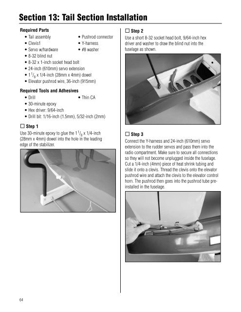
Section 13: Tail Section InstallationRequired Parts• Tail assembly• Pushrod connector• Clevis1• Y-harness• Servo w/hardware • #8 washer• 8-32 blind nut• 8-32 x 1-inch socket head bolt• 24-inch (610mm) servo extension• 1 1 / 8x 1/4-inch (28mm x 4mm) dowel• Elevator pushrod wire, 36-inch (915mm) Step 2Use a short 8-32 socket head bolt, 9/64-inch hexdriver and washer to draw the blind nut into thefuselage as shown.Required Tools and Adhesives• Drill• Thin CA• 30-minute epoxy• Hex driver: 9/64-inch• Drill bit: 1/16-inch (1.5mm), 5/32-inch (2mm) Step 1Use 30-minute epoxy to glue the 1 1 / 8x 1/4-inch(28mm x 4mm) dowel into the hole in the leadingedge of the stabilizer. Step 3Connect the Y-harness and 24-inch (610mm) servoextension to the rudder servos and pass them into theradio compartment. Make sure to secure all connectionsso they will not become unplugged inside the fuselage.Cut a 1/4-inch (4mm) piece of heat shrink tubing andslide it onto a clevis. Thread the clevis onto the elevatorpushrod wire and attach the clevis to the elevator controlhorn. The pushrod then goes into the pushrod tube preinstalledin the fuselage.64


