

ASSEMBLY MANUAL B-25 Mitchell ARF - RC DEPOT
ASSEMBLY MANUAL B-25 Mitchell ARF - RC DEPOT
ASSEMBLY MANUAL B-25 Mitchell ARF - RC DEPOT

You also want an ePaper? Increase the reach of your titles
YUMPU automatically turns print PDFs into web optimized ePapers that Google loves.
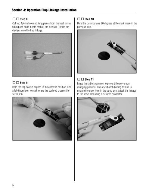
Section 4: Operation Flap Linkage Installation Step 8Cut two 1/4-inch (4mm) long pieces from the heat shrinktubing and slide it onto each of the clevises. Thread theclevises onto the flap linkage. Step 10Bend the pushrod wire 90 degrees at the mark made in theprevious step. Step 9Hold the flap so it is aligned in the centered position. Usea felt-tipped pen to mark where the pushrod crosses theservo arm. Step 11Leave the radio system on to prevent the servo fromchanging position. Use a 5/64-inch (2mm) drill bit toenlarge the outer hole in the servo arm. Attach the linkageto the servo arm using a pushrod connector.24


