WORKSHOP MANUAL KD 625/2 - Kohler Engines
WORKSHOP MANUAL KD 625/2 - Kohler Engines
WORKSHOP MANUAL KD 625/2 - Kohler Engines
- No tags were found...

You also want an ePaper? Increase the reach of your titles
YUMPU automatically turns print PDFs into web optimized ePapers that Google loves.
<strong>WORKSHOP</strong> <strong>MANUAL</strong><strong>KD</strong> <strong>625</strong>/2
DraftingbodyCUSE/ATLODocumentcodeED0053029380 51266REGISTRATION OF MODIFICATIONS TO THE DOCUMENTAny modifications to this document must be registered by the drafting body, by completing the following table.ModelN°EditionRevisionIssue dateReviewdate1° 0 06/07/2012 06/07/2012Endorsed- 2 - <strong>KD</strong> <strong>625</strong>-2 Workshop Manual_cod. ED0053029380_1° ed_ rev. 00
<strong>KD</strong> <strong>625</strong>/2PREFACE- Every attempt has been made to present within this service manual, accurate and up to date technical information.However, development on the KOHLER series is continuous.Therefore, the information within this manual is subject to change without notice and without obligation.The materials used by KOHLER to construct the engine's components undergo strict quality controls and the engine'sassembly guarantees reliability and long life.The engine has been built to the machine manufacturer's specifications, and it was its responsibility to adopt all the measuresneeded to meet the essential health and safety requirements as provided for by the laws in force; use of the engine for usesother than the one defined shall not be considered as compliant with the use intended by KOHLER, who therefore refuses allresponsibility for any injury arising from such an operation.- The information contained within this service manual is the sole property of KOHLER.As such, no reproduction or replication in whole or part is allowed without the express written permission of KOHLER.Information presented within this manual assumes the following:1 - The person or people performing service work on KOHLER series engines is properly trained and equipped to safely andprofessionally perform the subject operation;2 - The person or people performing service work on KOHLER series engines possesses adequate hand and KOHLER specialtools to safely and professionally perform the subject service operation;3 - The person or people performing service work on KOHLER series engines has read the pertinent information regarding thesubject service operations and fully understands the operation at hand.- This manual was written by the manufacturer to provide technical and operating information to authorised KOHLER after-salesservice centres to carry out assembly, disassembly, overhauling, replacement and tuning operations.- As well as employing good operating techniques and observing the right timing for operations, operators must read theinformation very carefully and comply with it scrupulously.- Time spent reading this information will help to prevent health and safety risks and financial damage.Written information is accompanied by illustrations in order to facilitate your understanding of every step of the operating phases.<strong>KD</strong> <strong>625</strong>-2 Workshop Manual_cod. ED0053029380_1° ed_ rev. 00- 3 -
-CALIFORNIA EMISSION CONTROL WARRANTY STATEMENTYOUR WARRANTY RIGHTS AND OBLIGATIONSThe California Air Resources Board and <strong>Kohler</strong> Co. are pleased to explain the emission control system warranty on your 2012 engine. InCalifornia, new heavy-duty off-road engines must be designed, built and equipped to meet the State’s stringent anti-smog standards. <strong>Kohler</strong> Co.must warrant the emission control system on your engine for the time period listed below provided there has been no abuse, neglect or impropermaintenance of your engine.Your emission control system may include parts such as the fuel-injection system and the air induction system. Also included may be hoses,connectors and other emission related assemblies.Where a warrantable condition exists, <strong>Kohler</strong> Co. will repair your heavy-duty off-road engine at no cost to you including diagnosis, parts and labor.MANUFACTURER’S WARRANTY COVERAGE:Your off-road, diesel engine emission control system is covered under warranty for a period of five (5) years or 3,000 hours, whichever occurs first,beginning on the date the engine or equipment is delivered to an ultimate purchaser for all constant speed engines with maximum power 19≤kW
CHAPTER INDEX-This manual contains pertinent information regarding the repair of KOHLER air-cooled, direct injection Diesel enginestype <strong>KD</strong> <strong>625</strong>-2 - <strong>625</strong>-2 EPA: updated 06/072012.INDEXCalifornia emission control warranty statement.................................................................................................................. 4Your warranty rights and obligations................................................................................................................................... 41 - GENERAL REMARKS AND SAFETY INFORMATION....................................................................................... 9Limited 3 year kohler ® diesel engine warranty................................................................................................................... 9General service manual notes............................................................................................................................................ 9Glossary and terminology................................................................................................................................................... 9Safety regulations...............................................................................................................................................................10General safety during operating phases............................................................................................................................11Safety and environmental impact ......................................................................................................................................112 - TECHNICAL INFORMATION............................................................................................................................. 12Trouble shooting.................................................................................................................................................................12Manufacturer and engine identification..............................................................................................................................14The identification plate shown in the figure can be found directly on the engine..............................................................14Approval data.....................................................................................................................................................................14Main components...............................................................................................................................................................15Techinical specifications.....................................................................................................................................................16Fuel supply circuit...............................................................................................................................................................17Lubrication circuit...............................................................................................................................................................17Electrical system................................................................................................................................................................17Performance diagram.........................................................................................................................................................18Overall dimension.............................................................................................................................................................. 203 - MAINTENANCE - RECOMMENDED OIL TYPE - REFILLING......................................................................... 22Routine engine maintenance............................................................................................................................................. 22Extraordinary maintenance .............................................................................................................................................. 22Ordinary maintenance ...................................................................................................................................................... 22Lubricant............................................................................................................................................................................ 23Prescribed lubricant.......................................................................................................................................................... 24Fuel recommendations...................................................................................................................................................... 254 - DISASSEMBLY / REASSEMBLY....................................................................................................................... 26Recommendations for disassembling and assembling..................................................................................................... 26Recommendations for overhauls and tuning.................................................................................................................... 26Air cleaner......................................................................................................................................................................... 26Oil-bath air cleaner............................................................................................................................................................ 26Dry air cleaner................................................................................................................................................................... 27Dry air cleaner, donaldson type........................................................................................................................................ 27Clogging indicator.............................................................................................................................................................. 28Oil vapour separator......................................................................................................................................................... 28Manifolds, intake/exhaust.................................................................................................................................................. 28Intake manifold.................................................................................................................................................................. 28Exhaust manifold............................................................................................................................................................... 28External alternator control belt (Only for engines with external alternator)...................................................................... 29External alternator blower control belt - disassembly....................................................................................................... 29External alternator blower control belt – tension check.................................................................................................... 29External alternator blower control belt - reassembly........................................................................................................ 29Fuel tank............................................................................................................................................................................ 29Pulley guard - shroud - side plates.................................................................................................................................... 30Cooling fan........................................................................................................................................................................ 30Hub.................................................................................................................................................................................... 30Internal alternator.............................................................................................................................................................. 30Shroud support (gear cover plate)......................................................................................................................................31Flywheel.............................................................................................................................................................................31Rocker arms.......................................................................................................................................................................31Valve / rocker arm clearance..............................................................................................................................................31Compression release (optional)........................................................................................................................................ 32<strong>KD</strong> <strong>625</strong>-2 Workshop Manual_cod. ED0053029380_1° ed_ rev. 00- 5 -
- Chapter indexRocker arm assembly........................................................................................................................................................ 32Injector............................................................................................................................................................................... 32Injector for epa and 97/68 ce engines............................................................................................................................... 33Injector projection.............................................................................................................................................................. 33Cylinder head.................................................................................................................................................................... 33Valves................................................................................................................................................................................ 34Valve stem sealing rings - reassembly............................................................................................................................. 34Valve springs..................................................................................................................................................................... 34Valve material.................................................................................................................................................................... 34Valve guides and valve guide housings............................................................................................................................ 35Valve guide insertion......................................................................................................................................................... 35Dimensions and clearance between guides and valves................................................................................................... 35Valve seats and housings.................................................................................................................................................. 36Valve seat grinding............................................................................................................................................................ 36Pushrod tube..................................................................................................................................................................... 36Cylinder............................................................................................................................................................................. 36Checks and cylinder roughness........................................................................................................................................ 36Piston................................................................................................................................................................................. 37Piston weight..................................................................................................................................................................... 38Piston rings - end gaps (mm)............................................................................................................................................ 38Pistons ringis - clearance between grooves (mm)............................................................................................................ 38Piston rings - fitting sequence........................................................................................................................................... 38Piston - refitting................................................................................................................................................................. 39Piston clearance................................................................................................................................................................ 39Connecting rod.................................................................................................................................................................. 39Connecting rod small end bushing.................................................................................................................................... 40Connecting rod alignment................................................................................................................................................. 40Connecting rod weight....................................................................................................................................................... 40Connecting rod big end bearing........................................................................................................................................ 40Crankshaft timing gear.......................................................................................................................................................41Main bearing supports........................................................................................................................................................41Main bearing support, gear side........................................................................................................................................41Main bearing support, flywheei side..................................................................................................................................41Crankshaft..........................................................................................................................................................................42Center main bearing support, locating screw....................................................................................................................42Crankshaft removal............................................................................................................................................................42Crankshaft center main bearing support............................................................................................................................42Crankshaft lubrication ducts...............................................................................................................................................42Crankshaft journal radius.................................................................................................................................................. 43Checking main journals and crank pins............................................................................................................................ 43Main journal and crank pin diameter................................................................................................................................. 43How to measure main bearing inside diameter................................................................................................................. 43Main bearing and connecting rod big end bearing inside diameter ................................................................................. 44Clearance between main journals/crank pins and connecting rod bearings.................................................................... 44Main bearíng supports - Dimensions................................................................................................................................ 44Main bearing housings...................................................................................................................................................... 44Crankshaft end play.......................................................................................................................................................... 45Camshaft........................................................................................................................................................................... 45How to measure camshaft journals and housings............................................................................................................ 45Dimensions of camshaft journals and housings............................................................................................................... 45How to measure intake/exhaust cam height..................................................................................................................... 46Camshaft end play............................................................................................................................................................ 46Camshaft timing................................................................................................................................................................ 46Valve timing without considering timing marks................................................................................................................. 46Valve timing check..............................................................................................................................................................47Valve timing - angles..........................................................................................................................................................47Hydraulic pump...................................................................................................................................................................47Hydraulic pump p.T.O.........................................................................................................................................................47Hydraulic pump components (1 p)..................................................................................................................................... 48Mechanical speed governor.............................................................................................................................................. 48Mechanical speed governor components......................................................................................................................... 48Governor springs with rocker arm system........................................................................................................................ 49Governor springs with single-spring system..................................................................................................................... 49Electronic speed governor (Optional)................................................................................................................................ 49Speed governor wiring diagram........................................................................................................................................ 50- 6 - <strong>KD</strong> <strong>625</strong>-2 Workshop Manual_cod. ED0053029380_1° ed_ rev. 00
Chapter index-5 - LUBRICATION SYSTEM.................................................................................................................................... 52Lubrication system and breather recirculation system...................................................................................................... 52Standard lubrication system circuit................................................................................................................................... 52Lubrication system with oil radiator circuit........................................................................................................................ 53Oil pump............................................................................................................................................................................ 53Oil filter cartridge (external)............................................................................................................................................... 54Oil pressure relief valve..................................................................................................................................................... 54Oil pressure check............................................................................................................................................................. 55Oil pressure curve with engine at idle speed.................................................................................................................... 55Oil pressure curve with engine at full speed..................................................................................................................... 55Oil radiator (on request)..................................................................................................................................................... 556 - FUEL SYSTEM.................................................................................................................................................... 56Fuel feeding / injection circuit............................................................................................................................................ 56Fuel feeding / injection circuit with fuel filter inside the fuel tank...................................................................................... 56Fuel feeding / injection circuit with external fuel filter........................................................................................................ 56Fuel feeding / injection circuit with external fuel filter and double solenoid valve............................................................. 56Fuel feeding / injection circuit with fuel filter inside the fuel tank and double solenoid valve........................................... 56Fuel feeding / injection circuit with external fuel filter and qsd (quick stop system).......................................................... 57Fuel filter............................................................................................................................................................................ 57Fuel filter (inside fuel tank)................................................................................................................................................ 57Fuel filter, external............................................................................................................................................................. 57Fuel lift pump..................................................................................................................................................................... 57Fuel feeding pump components........................................................................................................................................ 58Piston fuel lift pump (on request)....................................................................................................................................... 58Injection pump................................................................................................................................................................... 58Injection pump for standard and 97/68 ce engines........................................................................................................... 58Injection pump for epa engines......................................................................................................................................... 59Plunger and barrel assembly............................................................................................................................................ 59How to check plunger and barrel for internal leakage...................................................................................................... 59How to check injection pump delivery valve sealing......................................................................................................... 60Test data for injection pump delivery................................................................................................................................ 60How to reassemble injection pump components...............................................................................................................61How to mount injection pump on the engine......................................................................................................................61Injection pump/mechanical speed governor timing........................................................................................................... 62(Static) injection timing...................................................................................................................................................... 62Injection static advance adjustment.................................................................................................................................. 62Injection advance adjustment............................................................................................................................................ 63Injector............................................................................................................................................................................... 64Size s injector, only for standard engines......................................................................................................................... 64Size s nozzle, only for standard engines........................................................................................................................... 64Size p injector, for 97/68 ce and epa engines................................................................................................................... 65Size p nozzle, for 97/68 ce and epa engines.................................................................................................................... 65Injector setting................................................................................................................................................................... 657 - ELECTRIC SYSTEM........................................................................................................................................... 66Electric starting layout with internal alternator.................................................................................................................. 66Electrical starting layout with external alternator.............................................................................................................. 66Alternator........................................................................................................................................................................... 67Alternator - 12 v, 18a......................................................................................................................................................... 67Alternator battery charger curve (12 v, 18 a)..................................................................................................................... 67Alternator - 24 v, 6 a ........................................................................................................................................................ 67Alternator battery charger curve - 24 v, 6 a...................................................................................................................... 68Alternator - 12 v, 14 a ...................................................................................................................................................... 68Alternator battery charger curve standard - 12 v, 14 a.................................................................................................... 68Magnetization checking tool (part no. 7000-9727-001).................................................................................................... 68Checking for cable continuity............................................................................................................................................ 69Alternator, external - 12 v, 33 a......................................................................................................................................... 69Alternator battery charger curve - external, 12 v, 33 a..................................................................................................... 69Voltage regulator............................................................................................................................................................... 70How to check voltage regulator for proper operation........................................................................................................ 70Voltage regulator - 12v, 26a, with “w” terminal ..................................................................................................................71Voltage regulator - 12 v, 30 a ............................................................................................................................................71Voltage regulator - 12v, 30a, with “w” terminal ..................................................................................................................71Characteristic curves for starting motor type bosch - 12 v, 1.7 Kw................................................................................... 72<strong>KD</strong> <strong>625</strong>-2 Workshop Manual_cod. ED0053029380_1° ed_ rev. 00- 7 -
- Chapter indexStarting motor.................................................................................................................................................................... 72Characteristic curves of the 24 v 1.6 Kw starting motor.................................................................................................... 73Starting motor type bosch dw (r) 12 v, 1.7 Kw................................................................................................................... 73Pre-heating glow plug........................................................................................................................................................74Direct stop electromagnets................................................................................................................................................74Reverse electromagnet – fire version................................................................................................................................74Direct stop electromagnet..................................................................................................................................................758 - SETTINGS........................................................................................................................................................... 76Speed adjustments.............................................................................................................................................................76Idling speed setting in no-load conditions..........................................................................................................................76Full speed setting in no-load conditions (standard)...........................................................................................................76Injection pump delivery setting...........................................................................................................................................76Lnjection pump delivery limiting and extra fuel device......................................................................................................76Injection pump delivery setting with dynamometric brake................................................................................................ 77Lnjection pump delivery setting without dynamometric brake.......................................................................................... 77Setting the stop limit stop.................................................................................................................................................. 789 - STORAGE........................................................................................................................................................... 80Engine storage ................................................................................................................................................................. 80Protective treatment.......................................................................................................................................................... 80Preparing the engine for operation after protective treatment...........................................................................................8110 - TORQUE SPECIFICATIONS AND USE OF SEALANT.................................................................................. 82Table of tightening torques for the main components....................................................................................................... 82Table of tightening torques for standard screws (coarse thread)...................................................................................... 84Table of tightening torques for standard screws (fine thread)........................................................................................... 8411 - SPECIAL TOOLS.............................................................................................................................................. 85Special tools and equipment for maintenance.................................................................................................................. 85- 8 - <strong>KD</strong> <strong>625</strong>-2 Workshop Manual_cod. ED0053029380_1° ed_ rev. 00
GENERAL REMARKS AND SAFETY INFORMATION1LIMITED 3 YEAR KOHLER ® DIESEL ENGINE WARRANTY<strong>Kohler</strong> Co. warrants to the original retail consumer that each new KOHLER Diesel engine sold by <strong>Kohler</strong> Co. will be free from manufacturingdefects in materials or workmanship in normal service for a period of three (3) years or 2000 hours whichever occurs first from the date ofpurchase, provided it is operated and maintained in accordance with <strong>Kohler</strong> Co.’s instructions and manuals. If no hour meter is installed as originalequipment then 8 hours of use per day and 5 days per week will be used to calculate hours used.Our obligation under this warranty is expressly limited, at our option, to the replacement or repair at <strong>Kohler</strong> Co., <strong>Kohler</strong>, Wisconsin 53044, or at aservice facility designated by us of such parts as inspection shall disclose to have been defective.This warranty does not apply to defects caused by unreasonable use, including faulty repairs by others and failure to provide reasonable andnecessary maintenance.The following items are not covered by this warranty:Engine accessories such as fuel tanks, clutches, transmissions, power-drive assemblies and batteries, unless supplied or installed by <strong>Kohler</strong> Co.These are subject to the warranties, if any, of their manufacturers.KOHLER CO. AND/OR THE SELLER SHALL NOT BE LIABLE FOR SPECIAL, INDIRECT, INCIDENTIAL OR CONSEQUENTIAL DAMAGESOF ANY KIND, including but not limited to labor costs or transportation charges in connection with the repair or replacement of defective parts.IMPLIED OR STATUTORY WARRANTIES, INCLUDING WARRANTIES OF MERCHANTABILITY OR FITNESS FOR A PARTICULAR PURPOSE,ARE EXPRESSLY LIMITED TO THE DURATION OF THIS WRITTEN WARRANTY. We make no other express warranty, nor is any one authorizedto make any on our behalf.Some states do not allow limitations on how long an implied warranty lasts, or the exclusion or limitation of incidental or consequential damages,so the above limitation or exclusion may not apply to you.This warranty gives you specific legal rights, and you may also have other rights, which vary from state to state.To obtain warranty servicePurchaser must bring the engine to an authorized <strong>Kohler</strong> service facility. To locate the nearest facility, visit our website, www.kohlerengines.com,and use the locator function, consult your Yellow Pages or telephone 1-800-544-2444.ENGINE DIVISION, KOHLER CO., KOHLER, WISCONSIN 53044GENERAL SERVICE <strong>MANUAL</strong> NOTES1 - Use only genuine <strong>Kohler</strong> repair parts.Failure to use genuine <strong>Kohler</strong> parts could result in substandardperformance and low longevity.2 - All data presented are in metric format. That is, dimensionsare presented in millimeters (mm), torque is presented inNewton-meters (Nm), weight is presented in kilograms(Kg), volume is presented in liters or cubic centimeters (cc)and pressure is presented in barometric units (bar).GLOSSARY AND TERMINOLOGYFor clarity, here are the definitions of a number of terms usedrecurrently in the manual.- Cylinder number one: is the piston timing belt side «viewedfrom the flywheel side of the engine».- Rotation direction: anticlockwise «viewed from the flywheelside of the engine».<strong>KD</strong> <strong>625</strong>-2 Workshop Manual_cod. ED0053029380_1° ed_ rev. 00- 9 -
1 General remarks and safety informationSAFETY REGULATIONSGENERAL NOTES. <strong>Kohler</strong> engines are built to provide safe and longlastingperformances, but in order to obtain these results it isessential that the maintenance requirements described inthe manual are observed along with the following safetyrecommendations.. The engine has been built to the specifications of amachine manufacturer, and it is his responsibility to ensurethat all necessary action is taken to meet the essentialand legally prescribed health and safety requirements.Any use of the machine other than that described cannotbe considered as complying with its intended purposeas specified by <strong>Kohler</strong>, which therefore declines allresponsibility for accidents caused by such operations.. The following instructions are intended for the user of themachine in order to reduce or eliminate risks, especiallythose concerning the operation and standard maintenanceof the engine.. The user should read these instructions carefully and getto know the operations described. By not doing so he mayplace at risk his own health and safety and that of anyoneelse in the vicinity of the machine.. The engine may be used or mounted on a machine onlyby personnel suitably trained in its operation and aware ofthe dangers involved. This is particularly true for standardand, above all, special maintenance work. For specialmaintenance contact personnel trained specifically by<strong>Kohler</strong>. This work should be carried out in accordance withexisting literature.. <strong>Kohler</strong> declines all responsibility for accidents or for failureto comply with the requirements of law if changes are madeto the engine’s functional parameters or to the fuel flow rateadjustments and speed of rotation, if seals are removed,or if parts not described in the operating and maintenancemanual are removed and reassembled by unauthorizedpersonnel.WARNING. In addition to all other machine specifications, ensure thatthe engine is in a near horizontal position when starting. lfstarting manually, ensure that the necessary operationscan be performed without any risk of striking against wallsor dangerous objects. Rope starting (except for recoil ropestarting) is not permitted even in emergencies.. Check that the machine is stable so that there is no risk of itoverturning.. Get to know the engine speed adjustment and machinestop operations.. Do not start the machine in closed or poorly ventilatedenvironments. The internal combustion process generatescarbon monoxide, an odourless and highly toxic gas, sospending too long a time in an environment where theengine discharges its exhaust products freely can lead toloss of consciousness and even death.. The engine may not be used in environments containingflammable materials, explosive atmospheres or easilycombustible powders, unless adequate and specificprecautions have been taken and are clearly stated andcertified for the machine.. To prevent the risk of fire, keep the machine at a distance ofat least one metre from buildings or other machines.. Children and animals must be kept at a sufficient distancefrom the machine to prevent any danger resulting from itsoperation.. Fuel is flammable, so the tank must be filled only when theengine is turned off. Dry carefully any fuel that may havespilled, remove the fuel container and any cloths soakedin fuel or oil, check that any sound-absorbing panels madeof porous material are not soaked with fuel or oil, and makesure that the ground on which the machine is located has notabsorbed fuel or oil.. Before starting, remove any tools that have been used forcarrying out maintenance work to the engine and/or themachine and check that any guards removed have beenreplaced. In cold climates it is possible to mix kerosene withthe diesel fuel to make the engine easier to start. The liquidsmust be mixed in the tank by pouring in first the keroseneand then the diesel fuel. Consult <strong>Kohler</strong> technical office formixture proportions. Petrol may not be used because of therisk of it forming flammable vapours.. During operation the surface of the engine reachestemperatures that may be dangerous. Avoid in particular allcontact with the exhaust system.. The liquid cooling circuit is under pressure. Do not carry outany checks before the engine has cooled down, and eventhen open the radiator cap or the expansion tank cautiously.Wear protective clothing and glasses. lf there is an electricfan, do not approach the engine while it is still hot as the fanmay come on even when the engine is not running. Clean thecooling system with the engine turned off.. While cleaning the oil bath air filter, check that the oil isdisposed of in such a way as not to harm the environment.Any filtering sponges in the oil bath air filter should not besoaked with oil. The cyclone pre-filter cup must not be filledwith oil.. Since the oil must be emptied out while the engine is still hot(approx. 80°C), particular care should be taken in order toavoid burns. In any case make sure that oil does not comeinto contact with your skin because of the health hazardsinvolved.. Fuel vapours are highly toxic, so fill up only in the open air orin well ventilated environments.. During operations which involve access to moving parts ofthe engine and/or removal of the rotary guards, disconnectand insulate the positive cable of the battery so as to preventaccidental short circuits and activation of the starter motor.. Check the belt tension only when the engine is turned off.IMPORTANT. To start the engine follow the specific instructions providedin the engine and/or machine operating manual. Do notuse auxiliary starting devices not originally installed on themachine (e.g. Startpilot systems which utilise ether etc.). Before carrying out any work on the engine, turn it off andallow it to cool down. Do not perform any operation while theengine is running.. Check that the discharged oil, the oil filter and the oilcontained in the oil filter are disposed of in such a way as notto harm the environment.. Close the fuel tank filler cap carefully after each fíllingoperation. Do not fill the tank right up to the top, but leavesufficient space to allow for any expansion of the fuel.. Do not smoke or use naked flames while filling.- 10 - <strong>KD</strong> <strong>625</strong>-2 Workshop Manual_cod. ED0053029380_1° ed_ rev. 00
General remarks and safety information1. Take care when removing the oil filter as it may be hot.. The operations of checking, filling up and replacing thecooling liquid must be carried out with the engine turned offand cold. Take particular care if liquids containing nitritesare mixed with others not containing these compoundsas this may give rise to the formation of nitrosamineswhich are a health hazard. The cooling liquid is polluting,so dispose of in a manner that does not damage theenvironment.. In order to move the engine simultaneously use theeyebolts fitted for this purpose by <strong>Kohler</strong>. These liftingpoints are however not suitable for the entire machine, soin this case use the eyebolts fitted by the manufacturer.GENERAL SAFETY DURING OPERATING PHASES– The procedures contained in this manual have beentested and selected by the manufacturer’s technicalexperts, and hence are to be recognised as authorisedoperating methods.– Some tools are normal workshop ones, while others arespecial tools designed by the Manufacturer of the engine.– All tools must be in good working condition so that enginecomponents are not damaged and that operations arecarried out properly and safely.– It is important to wear the personal safety devicesprescribed by work safety laws and also by the standardsof this manual.– Holes must be lined up methodically and with the aid ofsuitable equipment. Do not use your fingers to carry outthis operation to avoid the risk of amputation.– Some phases may require the assistance of more thanone operator. If so, it is important to inform and train themregarding the type of activity they will be performing inorder to prevent risks to the health and safety of all personsinvolved.– Do not use flammable liquids (petrol, diesel, etc.) todegrease or wash components. Use special products.– Use the oils and greases recommended by the manufacturer.Do not mix different brands or combine oils with differentcharacteristics.– Discontinue use of the engine if any irregularities arise,particularly in the case of unusual vibrations.– Do not tamper with any devices to alter the level ofperformance guaranteed by the manufacturer.SAFETY AND ENVIRONMENTAL IMPACTEvery organisation has a duty to implement procedures to identify,assess and monitor the influence of its own activities (products,services, etc.) on the environment.Procedures for identifying the extent of the impact on the environmentmust consider the following factors:- Liquid waste;- Waste management;- Soil contamination;- Atmospheric emissions;- Use of raw materials and natural resources;- Regulations and directives regarding environmental impact.In order to minimise the impact on the environment, the manufacturernow provides a number of indications to be followed by all personshandling the engine, for any reason, during its expected lifetime.- All packaging components must be disposed of in accordancewith the laws of the country in which disposal is taking place.- Keep the fuel and engine control systems and the exhaustpipes in efficient working order to limit environmental and noisepollution.- When discontinuing use of the engine, select all componentsaccording to their chemical characteristics and dispose of themseparately.California Proposition 65WARNINGEngine exhaust from this product containschemicals known to the State of California to causecancer, birth defects, or other reproductive harm.<strong>KD</strong> <strong>625</strong>-2 Workshop Manual_cod. ED0053029380_1° ed_ rev. 00- 11 -
2TECHNICAL INFORMATIONTROUBLE SHOOTINGTHE ENGINE MUST BE STOPPED IMMEDIATELY WHEN:1) - The engine rpms suddenly increase and decrease;2) - A sudden and unusual noise is heard;3) - The colour of the exhaust fumes suddenly darkens;4) - The oil pressure indicator light turns on while running.TABLE OF LIKELY ANOMALIES AND THEIR SYMPTOMSThe following table contains the possible causes of some failures which may occur during operation.Always perform these simple checks before removing or replacing any part.PROBLEMPOSSIBLE CAUSEEngine doesnot startEngine startsbut stopsNo accelerationNon-uniformspeedBlack smokeWhite smokeOil preassuretoo lowOverheatsInadequate performanceExcessive oilconsumptionHigh noiselevelObstructed fuel lineFuel filter cloggedFUELCIRCUITAir or water leaks in fuel systemThe tank cap vent hole is cloggedNo fuelFaulty fuel feeding pumpExtra fuel control level stickingCOOLINGCIRCUITClogged air filterCooling circuit cloggedIncorrect governor linkage adjustmentGovernor spring broken or unhookedLow idle speedRings worn or stickingWorn cylinderSETTINGS REPAIRSWorn main con rod-rocker arm bearingsBadly sealed intake valveHead tightening nuts looseDamaged cylinder head gasketExcessive valve-rocker arm clearanceNo clearance between valves androcker armsValves sticking or damagedDefective timing systemBent rodsCrankshaft not turning freely- 12 - <strong>KD</strong> <strong>625</strong>-2 Workshop Manual_cod. ED0053029380_1° ed_ rev. 00
Technical information2PROBLEMPOSSIBLE CAUSEEngine doesnot startEngine startsbut stopsNo accelerationNon-uniformspeedBlack smokeWhite smokeToo low oilpressureOverheatsInadequateperformanceExcessive oilconsumptionHigh noiselevelDamaged, blocked or dirty injectorInjection pump valve damagedInjector not adjustedMAINTENANCE INJECTIONLUBRICATIONCIRCUITELECTRICSYSTEMHardened pump control rodBroken or loose supplementarystart-up springWorn or damaged pumping elementIncorrect tuning of injection components(delivery balancing advance)Extra fuel control level stickingOil level too highOil level lowOil pressure valve blocked or dirtyOil pressure regulator not adjustedWorm oil pumpOil sump suction line cloggedFaulty pressure gauge or pressureswitchBlocked draining pipeDischarged batteryCable connection uncertain orincorrectFaulty starting switchFaulty starting motorExcessive idle operationIncomplete run-inOverloaded engineNon-conforming engine oil<strong>KD</strong> <strong>625</strong>-2 Workshop Manual_cod. ED0053029380_1° ed_ rev. 00- 13 -
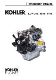
2 Technical informationMANUFACTURER AND ENGINE IDENTIFICATIONThe identification plate shown in the figure can be found directly on the engine.It contains the following information:A) Manufacturer’s identityB) Engine typeC) Engine serial numberD) Maximum operating speedE) Number of the customer version (form K)F) Approval dataApproval dataThe approval reference directives EC are on the engine plate (F).ABDCEF- 14 - <strong>KD</strong> <strong>625</strong>-2 Workshop Manual_cod. ED0053029380_1° ed_ rev. 00
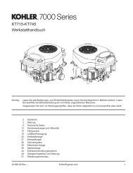
Technical information2MAIN COMPONENTS12 3612114758 910Components:1) Fuel tank2) Injectors3) Air cleaner4) Starting motor5) Oil filter6) Rocker arm cover7) Oil dipstick8) Throttle and stop controls9) Oil drain plug10) Fuel feeding pump11) Flywheel12) Injection pump<strong>KD</strong> <strong>625</strong>-2 Workshop Manual_cod. ED0053029380_1° ed_ rev. 00- 15 -
2Technical informationTECHINICAL SPECIFICATIONSOperating cycleCylindersBore x strokeDisplacementsCompression rateIntakeCoolingCrankshaft rotationCombustion sequenceTiming system<strong>KD</strong> <strong>625</strong>-2<strong>KD</strong> <strong>625</strong> engine type<strong>KD</strong> <strong>625</strong>-2NR CE<strong>KD</strong> <strong>625</strong>-2EPAGENERAL DETAILSFour-stroke dieseln°mmcm 395x8812482 in line95x88124895x88124817.5:1 20.0:1 21.0:1Oil bath air cleaner with cyclonic prefilter or dry air cleanerAir (fan integral to the flywheel)Counter-clockwise (from flywheel side)Driving shaft degrees180°Rods and rocker armsValvesn°2 per cylinderShaftSide camshaft in the crankcaseTappetsMechanicFuel injectionDirectDry weight of engineMaximum tilt while operatingKgMomentary11035°11035°11035°Maximum tilt while operatingUp to 1 hour25° 25° 25°Combustion air volume at 3000 r.p.m.l/min1600 1600 1600Cooling air volume at 3000 r.p.m.l/min26300 26300 26300POWER AND TORQUEMaximum operating speedr.p.m.3000 3000 3000N (80/1269/CEE) ISO 158520.7/28 - -Maximum powerNB ISO 3046 IFNNA ISO 3046 ICXNkW/CV18.8/25.516.9/2318.8/25.516.9/2318.8/25.516.9/23Maximum torque*Axial load allowed on crankshaftNm/KgmKg73./7.430067/6.830068/6.9300CONSUMPTION AT MAXIMUM POWERSpecific fuel onsumptionOil consumptiong/kWh - g/CV1hKg/h253-1860.013258-1900.013258-1900.013* 2200 rpm x <strong>KD</strong> <strong>625</strong>-2; 2000rpm x <strong>KD</strong><strong>625</strong>-2 NR/CE and 1700rpm x <strong>KD</strong> <strong>625</strong>-2 EPA- 16 - <strong>KD</strong> <strong>625</strong>-2 Workshop Manual_cod. ED0053029380_1° ed_ rev. 00
2 Technical informationPERFORMANCE DIAGRAM<strong>KD</strong> <strong>625</strong>-2 EPA @ 3000 r.p.m.<strong>KD</strong> <strong>625</strong> NR @ 2800 r.p.m.<strong>KD</strong> <strong>625</strong> @ 3000 r.p.m.- 18 - <strong>KD</strong> <strong>625</strong>-2 Workshop Manual_cod. ED0053029380_1° ed_ rev. 00
Technical information2........................................................................................................................................................................................................................................................................................................................................................................................................................................................................................................................................................................................................................................................................................................................................................................................................................................................................................................................................................................................................................................................................................................................................................................................................................................................................................................................................................................................................................................................................................................................................................................................................................................................................................................................................................................................................................................................................................................................................................................................................................................................................................................................................................................................................................................................................................................................................................................................................................................................................................................................................................................................................................................................................................................................................................................................................................................................................................................................................................................................................................................................................................................................................................................................................................................................................................................................................................................................................................................................................................................................................................................................................................................................................................................................................................................................................................................................................................................................................................................................................................................................................................................................................................................................................................................................................................................................................................................................................................................................................................................................................................................................................................................................................................................................................................................................................................................................................................................................................................................................................................................................................................................................................................................................................................................................................................................................................................................................................................................................................................................................................................................................................................................................................................................................................................................................................................................................................................................................................................................................................................................................................................................................................................................................................................................................................................................................................................................................................................................................................<strong>KD</strong> <strong>625</strong>-2 Workshop Manual_cod. ED0053029380_1° ed_ rev. 00- 19 -
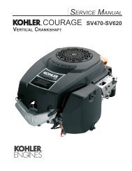
2Technical informationOVERALL DIMENSION<strong>KD</strong> <strong>625</strong>-2DIMENSIONI mm - MESURES mm - DIMENSION mm - EINBAUMAßE mm - DIMENSIONE mm - DIMENÇÕES (mm)A434C557E340G198I421M599O207B397D217F168H425L178N633P542- 20 - <strong>KD</strong> <strong>625</strong>-2 Workshop Manual_cod. ED0053029380_1° ed_ rev. 00
Technical information2........................................................................................................................................................................................................................................................................................................................................................................................................................................................................................................................................................................................................................................................................................................................................................................................................................................................................................................................................................................................................................................................................................................................................................................................................................................................................................................................................................................................................................................................................................................................................................................................................................................................................................................................................................................................................................................................................................................................................................................................................................................................................................................................................................................................................................................................................................................................................................................................................................................................................................................................................................................................................................................................................................................................................................................................................................................................................................................................................................................................................................................................................................................................................................................................................................................................................................................................................................................................................................................................................................................................................................................................................................................................................................................................................................................................................................................................................................................................................................................................................................................................................................................................................................................................................................................................................................................................................................................................................................................................................................................................................................................................................................................................................................................................................................................................................................................................................................................................................................................................................................................................................................................................................................................................................................................................................................................................................................................................................................................................................................................................................................................................................................................................................................................................................................................................................................................................................................................................................................................................................................................................................................................................................................................................................................................................................................................................................................................................................................................................................<strong>KD</strong> <strong>625</strong>-2 Workshop Manual_cod. ED0053029380_1° ed_ rev. 00- 21 -
3MAINTENANCE - RECOMMENDED OIL TYPE - REFILLINGROUTINE ENGINE MAINTENANCEImportantFailure to carry out the operations described in the table may lead to technical damage to the machine and/or systemEXTRAORDINARY MAINTENANCEAFTER THE FIRST50 WORKING HOURSEngine oil replacement.Oil filter replacement.ORDINARY MAINTENANCEOPERATION DESCRIPTIONENGINE OIL LEVELFREQUENCY x HOURS10 125 250 500 1000 2500 5000OIL BATH AIR CLEANERDRY AIR CLEANER(***)(***)FUEL PIPESCHECKEXTERNAL ALTERNATOR BELT TENSIONCOOLING SYSTEM CLEANINGVALVE-ROCKER ARMS CLEARANCEADJUSTMENTSETTING AND INJECTORS CLEANINGRUBBER INTAKE HOSE (DRY AIRCLEANER - INTAKE MANIFOLD)FUEL TANK CLEANINGALTERNATOR AND STARTING MOTORENGINE OILEXTERNAL OIL FILTERFUEL FILTEREXTERNAL ALTERNATOR BELT(**)(***)(*)(*)(*)REPLACEMENTRUBBER INTAKE HOSE (DRY AIRCLEANER - INTAKE MANIFOLD)FUEL PIPES(**)(**)DRY AIR CLEANER EXTERNALCARTRIDGEDRY AIR INTERNAL EXTERNALCARTRIDGEPARTIAL(***)(***)AFTER 6 CHECKS WITH CLEANINGAFTER 3 CHECKS WITH CLEANINGOVERHAULTOTAL(*) - In case of low use: every year.(**) - In case of low use: every 2 years.(***) - The period of time that must elapse before cleaning or replacing the filter element depends on the environment in which the engine operates.The air filter must be cleaned and replaced more frequently In very dusty conditions.- 22 - <strong>KD</strong> <strong>625</strong>-2 Workshop Manual_cod. ED0053029380_1° ed_ rev. 00
Maintenance - Recommended oil type - Refilling3LUBRICANTSAE ClassificationIn the SAE classification, oils differ on the basis of theirviscosity, and no other qualitative characteristic is takeninto account.The first number refers to the viscosity when the engineis cold (symbol W = winter), while the second considersviscosity with the engine at régime.The criteria for choosing must consider, during winter, thelowest outside temperature to which the engine will be subjectand the highest functioning temperature during summer.Single-degree oils are normally used when the runningtemperature varies scarcely.Multi-degree oil is less sensitive to temperature changes.- - - - - - - -40 35 30 25 20 15 10 5 0SAE 10W*+5SAE 20W*SAE 10W-30**SAE 30*SAE 10W-40**SAE 10W-60**SAE 15W-40 **SAE 15W-40 **SAE 5W-30 ***SAE 0W-30 ***+ + + + + + + +10 15 20 25 30 35 40 45SAE 40*SAE 20W-60 **SAE 5W-40 ***+50SAE- Grade* Mineral base** Semi-synthetic base*** Synthetic baseInternational specificationsThey define testing performances and procedures that the lubricants need to successfully respond to in several engine testing andlaboratory analysis so as to be considered qualified and in conformity to the regulations set for each lubrication kind.A.P.I : ( American Petroleum Institute )MIL : Engine oil U.S. military specifications released for logistic reasonsACEA : European Automobile Manufacturers AssociationTables shown on this page are of useful reference when buying a kind of oil.Codes are usually printed-out on the oil container and the understanding of their meaning is useful for comparing different brandsand choosing the kind with the right characteristics.Usually a specification showing a following letter or number is preferable to one with a preceding letter or number.An SF oil, for instance, is more performing than a SE oil but less performing than a SG one.ACEA Regulations - ACEA SequencesPetrolA1 = Low-viscosity, for frictions reductionA2 = StandardA3 = High performancesLight duty diesel enginesB1 = Low-viscosity, for frictions reductionB2 = StandardB3 =High performances (indirect injection)B4 = High quality (direct injection)Heavy duty diesel enginesE1 = OBSOLETEE2 = StandardE3 = Heavy conditions (Euro 1 - Euro 2 engines )E4 = Heavy conditions(Euro 1 - Euro 2 - Euro 3 engines )E5 = High performances in heavy conditions (Euro 1 - Euro 2 - Euro3 engines )API / MIL SequencesDIESELPETROLAPI CH-4 CG-4 CF-4 CF-2 CF CE CD CC SC SD SE SF SG SH SJ SLMILL- 46152 D / ECURRENTOBSOLETE<strong>KD</strong> <strong>625</strong>-2 Workshop Manual_cod. ED0053029380_1° ed_ rev. 00- 23 -
3Maintenance - Recommended oil type - RefillingPRESCRIBED LUBRICANTAGIP SUPERDIESELMULTIGRADE specifications10W40API CF4 / SGACEA B2 - E2MIL - L-4165 D/EIn the countries where AGIP products are not available, use oil API SJ/CF for Diesel engines or oil corresponding to the militaryspecification MIL-L-4165 D/E.For a temperature of -10°C an oil with a 5W40 viscosity is recommended.For a temperature of -15°C an oil with a 0W30 viscosity is recommended.<strong>KD</strong> <strong>625</strong>/2 ENGINES OIL CAPACITYOIL VOLUME AT MAX LEVEL (OIL FILTER INCLUDED)OIL VOLUME AT MAX LEVEL (WITHOUT OIL FILTER)LitresLitres3.12.8Danger - Attention- The engine may be damaged if operated with insufficient lube oil.- It is also dangerous to supply too much lube oil to the engine because a sudden increase in engine rpm could be causedby its combustion.- Use proper lube oil preserve your engine.Good quality or poor quality of the lubricating oil has an affect on engine performance and life.- If inferior oil is used, or if your engine oil is not changed regularly, the risk of piston seizure, piston ring sticking, andaccelerated wear of the cylinder liner, bearing and other moving components increases significantly.- Always use oil with the right viscosity for the ambient temperature in which your engine is being operated.Danger - Attention- The used engine oil can cause skin-cancer if kept frequently in contact for prolonged periods.- If contact with oil cannot be avoided, wash carefully your hands with water and soap as soon as possible.- Do not disperse the oil in the ambient, as it has a high pollution power.- 24 - <strong>KD</strong> <strong>625</strong>-2 Workshop Manual_cod. ED0053029380_1° ed_ rev. 00
Maintenance - Recommended oil type - Refilling3FUEL RECOMMENDATIONSPurchase diesel fuel in small quantities and store in clean, approved containers. Clean fuel prevents the diesel fuel injectors andpumps from clogging. Do not overfill the fuel tank.Leave room for the fuel to expand. Immediately clean up any spillage during refueling.Never store diesel fuel in galvanized containers; diesel fuel and the galvanized coating react chemically to each other, producingflaking that quickly clogs filters or causes fuel pump or injector failure.High sulfur content in fuel may cause engine wear. In those countries where diesel has a high sufur content, its is advisable tolubricate the engine with a high alkaline oil or alternatively to replace the lubricating oil recommended by the manufacturer morefrequently. The regions in which diesel normally has a low sulfur content are Europe, North America, and Australia.PRESCRIBED LUBRICANTFuel with low sulphur contentFuel with high sulphur contentAPI CF4 - CG4API CFFUEL TYPEFor best results, use only clean, fresh, commercial-grade diesel fuel. Diesel fuels that satisfy the following specifications aresuitable for use in this engine: ASTM D-975 - 1D or 2D, EN590, or equivalent.FUELS FOR LOW TEMPERATURESIt is possible to run the engine at temperatures below 0°C using special winter fuels. These fuels reduce the formation of paraffinin diesel at low temperatures. If paraffin forms in the diesel, the fuel filter becomes blocked interrupting the flow of fuel.Fuel can be: - Summer up to 0°C- Winter up to -10°C- Alpine up to -20°C- Arctic up to -30°CBIODIESEL FUELFuels containing less than 20% methyl ester or B20, are suitable for use in thisengine. Biodiesel fuels meeting the specification of BQ-9000, EN 14214 or equivalentare recommended. DO NOT use vegetable oil as a biofuel for this engine.Any failures resulting from the use of fuels other than recommended will not bewarranted.AVIATION FUELAviation fuels suitable for use in this engine include JP5, JP4, JP8 and, JET-A (if5 percent oil is added).EMISSION CONTROL INFORMATIONLOW SULFUR FUEL ORULTRA LOW SULFUR FUEL ONLYEPA /CARB emission label must beattached near the fuel inlet.Capacities standard fuel tankLitres10As for filters, tanks and special crankcases please refer to <strong>Kohler</strong> instructions.<strong>KD</strong> <strong>625</strong>-2 Workshop Manual_cod. ED0053029380_1° ed_ rev. 00- 25 -
4DISASSEMBLY / REASSEMBLYRECOMMENDATIONS FOR DISASSEMBLING AND ASSEMBLINGImportantTo locate specific topics, the reader should refer to theindex.– Besides disassembly and reassembly operations this chapteralso includes checking and setting specifications, dimensions,repair and operating instructions.– Always use original <strong>Kohler</strong> spare parts for proper repairoperations.– The operator must wash, clean and dry components andassemblies before installing them.– The operator must make sure that the contact surfaces areintact, lubricate the coupling parts and protect those that areprone to oxidation.– Before any intervention, the operator should lay out all equipmentand tools in such a way as to enable him to carry outoperations correctly and safely.– For safety and convenience, you are advised to place theengine on a special rotating stand for engine overhauls.– Before proceeding with operations, make sure that appropriatesafety conditions are in place, in order to safeguardthe operator and any persons involved.– In order to fix assemblies and/or components securely, theoperator must tighten the fastening parts in a criss-cross oralternating pattern.– Assemblies and/or components with a specific tighteningtorque must initially be fastened at a level lower than theassigned value, and then subsequently tightened to the finaltorque.RECOMMENDATIONS FOR OVERHAULS AND TUNINGImportantTo locate specific topics, the reader should refer to the index.– Before any intervention, the operator should lay out all equipmentand tools in such a way as to enable him to carry outoperations correctly and safely.– The operator must comply with the specific measures describedin order to avoid errors that might cause damage to theengine.– Before carrying out any operation, clean the assembliesand/or components thoroughly and eliminate any depositsor residual material.– Wash the components with special detergent and do not usesteam or hot water.– Do not use flammable products (petrol, diesel, etc.) to degreaseor wash components. Use special products.– Dry all washed surfaces and components thoroughly with ajet of air or special cloths before reassembling them.– Apply a layer of lubricant over all surfaces to protect themagainst oxidation.– Check all components for intactness, wear and tear, seizure,cracks and/or faults to be sure that the engine is in goodworking condition.– Some mechanical parts must be replaced en bloc, togetherwith their coupled parts (e.g. valve guide/valve etc.) as specifiedin the spare parts catalogue.AIR CLEANEROil-bath air cleanerCheck gaskets and replace if necessary.Check that flange weld is free of porosity or defective spots.Carefully clean bowl and filtering element with Diesel oil and blowthrough with compressed air.Top up with engine oil to the mark. When refitting tighten nuts at 25 Nm. See page 22 for periodic maintenance details.1- 26 - <strong>KD</strong> <strong>625</strong>-2 Workshop Manual_cod. ED0053029380_1° ed_ rev. 00
Disassembly / Reassembly4Components:1 Bowl2 Oil level mark3 Filtering element4 Seal ring5 Internal seal ring6 Cover7 Clamp8 Prefilter2Dry air cleanerComponents:1 Hand wheel2 Cover3 Cartridge4 Seal ring5 Bracket6 Clogging indicatorImportantReplace cartridge immediately when indicator shows that is clogged.3Dry air cleaner, Donaldson typeDanger - AttentionNever clean the filter element using highly flammable solvents.It could cause an explosion! In order to know how often you should check and replace the airfilter cartridge and the rubber hose (air filter – intake manifold) seepage 22.41 Main cartridge2 Safety cartridge3 Axial cover4 Scavenging valve5 Cap complete with clampScavenging valve 4 must be positioned as in figure 4.Danger - AttentionDuring repair operations, when using compressed air, wear eyeprotection.The cartridge can be cleaned by blowing compressed air breadthwaysoutside and inside the cartridge, at a pressure not greater than 5atmospheres, or in necessity case by knocking the front of the cartridgeseveral times against a flat surface.Use a lamp to check that the filter element is not damaged or inspect itagainst the light while slanted.In case of doubt, install a new cartridge.<strong>KD</strong> <strong>625</strong>-2 Workshop Manual_cod. ED0053029380_1° ed_ rev. 00- 27 -
4Disassembly / ReassemblyClogging indicatorComponents:1 Reset button2 Transparent indicatorNote:Indicator is calibrated at 600÷650 mm column of water.5Oil vapour separatorFitted on engines with dry air cleaner.Screw it out of the air conveyor support, carefully wash with gasolineinside and blow out with compressed air.When refitting replace the copper gasket and connect the oil vapourseparator with intake manifold by means of the special rubber hose.67MANIFOLDS, INTAKE/EXHAUSTIntake manifoldTo avoid flange breakage check that heads are in line before tighteningnuts.Check flange surface for warpage and correct if necessary.Replace gaskets. Tighten nuts at 25 Nm.Note: In case of low temperature starting we can supply a manifoldwith possibility of fitting a glow plug with air preheating.8Exhaust manifoldCheck that the inside is clean.To avoid flange breakage check that heads are in line before tighteningnuts.Replace gaskets. Tighten nuts at 20 Nm.9- 28 - <strong>KD</strong> <strong>625</strong>-2 Workshop Manual_cod. ED0053029380_1° ed_ rev. 00
Disassembly / Reassembly4EXTERNAL ALTERNATOR CONTROL BELT(only for engines with external alternator)External alternator blower control belt - DisassemblyRelease the two alternator fastening bolts.Unscrew the fastening nuts of the belt guard and remove it.Remove the V belt. See page 22 for periodic maintenance details.10External alternator blower control belt – Tension checkImportantCarry out checks only after isolating the positive battery cable toprevent accidental short-circuiting and, consequently, the activationof the starter motor.Tension the belt if it flexes more than 1 cm exerting a pressure of10 kg.11External alternator blower control belt - ReassemblyInstall the belt and the belt guard.Force the alternator outwards and temporarily tighten the fasteningbolts.Make sure that the belt tension is within the required parameters (see“External alternator blower control belt – Tension check”, Fig. 11). Tighten the fastening bolts to a final torque of 30 Nm (8x1.25) and50 Nm (10x1.50).12FUEL TANKAfter disconnecting the fuel pipes unscrew the anchoring brackets'screws and remove the fuel tank.Completely empty the tank and check that no impurities are found inside.If the fuel tank is fitted wth an internal fuel filter remove and replacethe cartridge.Check that cap breather hole is not clogged.Remove the tank support. When refitting tighten the support screws at 40 Nm and the bracketscrews at 8 Nm.13 See page 57 for refitting internal fuel filter.<strong>KD</strong> <strong>625</strong>-2 Workshop Manual_cod. ED0053029380_1° ed_ rev. 00- 29 -
4Disassembly / ReassemblyPulley guard - Shroud - Side platesComponents:1 Pulley guard2 Shroud3 Side platesThe pulley guard is made of sound deadening material: it reduces thenoise that both the pulley and the fan tend to amplify.Shroud and side plates are made of ANTIFON, an elastic Iayer whichabsorbs the noise caused by the plate vibrations.14Cooling fanCarefully clean and check all blades and inserts. Replace the fan evenif there is only a single damaged blade or only a single released insert. See page 16 for cooling air flow. Tighten the fan's fixing screws at a torque of 10 Nm.15HubComponents:1 Hub2 Alternator rotor3 Fan4 BoltThe hub holds the alternator rotor and the cooling fan. Unscrew the bolt clockwise and tighten at 160 Nm when refitting.16Internal alternatorRemove stator and place it inside the rotor to prevent metal particlesfrom being attracted by the magnets. When refitting tighten rotor screws and stator bolts at 10 Nm. See page 67 ÷ 69 for alternator characteristics.17- 30 - <strong>KD</strong> <strong>625</strong>-2 Workshop Manual_cod. ED0053029380_1° ed_ rev. 00
Disassembly / Reassembly4Shroud support (Gear cover plate)Loosen screws and remove shroud support very carefully to avoiddamage to the oil seal ring.When refitting check that gaskets A and oil seal ring B are well insidetheir housings. Tighten screws at 25 Nm.18FLYWHEELRemove flywheel with puller 1 (part N°. 7271-1460-119).Check starter ring gear and tapered crankshaft mating surfaces. When refitting tighten bolt al 300 Nm.In order to replace the ring gear, it is necessary to disassemble theflywheel.Cut the ring gear in several places using a chisel and remove it.19ImportantRemove any debris and carefully clean the ring gear.Heat the new ring gear uniformly and keep it at a temperature of 300°Cfor15÷20 minuti.Danger – AttentionRisk of burning: be careful of hot surfaces.Insert the ring gear into its seat and place it carefully on the rim of theflywheel.Leave to the ring gear to cool gently before reassembling the flywheel.20ROCKER ARMSValve / Rocker arm clearanceImportantSetting should be performed when the engine is cold.Remove rocker arm cover and check gaskets for breakage.Bring each cylinder piston to top dead center on the compressionstroke and set clearance A al 0.15÷0.20 mm for intake and 0.30÷0.35mm for exhaust.21 22 When refitting tighten cover screws by 20 Nm.<strong>KD</strong> <strong>625</strong>-2 Workshop Manual_cod. ED0053029380_1° ed_ rev. 00- 31 -
4Disassembly / ReassemblyCompression release (optional)Bring piston to top dead center on the compression stroke.Unscrew rocker arm cover side plug and measure clearance A betweenlever and rocker arm, which must be 0.30÷0.40 mm.For setting purposes remove the rocker arm cover, unscrew the locknut C and set clearance A by changing the height of the shims underthe plate B.Set the valve/rocker arm clearance, see "Valve / Rocker arm clearance"on page 31.Reassemble the rocker arm cover and check the decompression leverclearance again.23Rocker arm assemblyComponents:1 Bore2 Lubrication tubeDimensions (mm):A = 18.032÷18.050B = 17.989÷18.000If clearance (A - B) exceeds 0.135 mm replace shaft and rocker arms.2425Caution – WarningWhen retitting check that lubrication tube perfectly matches withthe journal bore.On slow engines, which are set to 1,500 – 1,800 rpm, the rocker armsdiffer from the standard version in the upper part of the lubricationchannel. Tighten the rocker arm shaft fastening screws to the head at a torqueof 25 Nm.INJECTORClean injector and check calibrated pressure as indicated on page 65.When refitting check that it correctly protrudes from the cylinder headplane. Tighten the fixing nuts at 10 Nm. Tighten the high-pressure pipe union at 25 Nm.26- 32 - <strong>KD</strong> <strong>625</strong>-2 Workshop Manual_cod. ED0053029380_1° ed_ rev. 00
Disassembly / Reassembly4Injector for EPA and 97/68 CE enginesThe injector is attached to the cylinder head via a forked bracket. Tighten the fixing bracket screw at 10 Nm. Fix the high-pressure hose union to the injector union at 25 Nm.27Injector projectionThe end of nozzle A should project 3.0÷3.5 mm. from the cylinder headplane.Adjust injector projection by means of copper shims B measuring 0.5,1.00 and 1.50 mm in thickness.28CYLINDER HEADImportantDo not remove it when hot to avoid deformation.The cylinder heads must be tightened with the exhaust or intakemanifold mounted to keep them lined up.29lf cylinder head is deformed level it off by removing a maximum of 0.3mm.When refitting tighten only if sure that rocker arm lubrication tube iswell inside its holes, and that the rubber seals of the tappet hose areassembled and inserted correctly into their seats.Always replace copper head gasket: see page 39 for choosing the rightthickness. Progressively tighten nuts in the 1, 2, 3, 4 sequence at 55 Nm.<strong>KD</strong> <strong>625</strong>-2 Workshop Manual_cod. ED0053029380_1° ed_ rev. 00- 33 -
4Disassembly / ReassemblyValvesComponents:1 Intake valve2 Spring seat3 Valve stem seal ring4 Spring5 Retainer6 Half colletsTo remove half collets firmly press down as shown in the figure.30 31Valve stem sealing rings - ReassemblyLubricate the inside of the sealing ring with Molikote BR2 Plus andinsert them all the way onto the guides using tool 1460-108.To prevent deformation of the sealing ring 1 as it is inserted onto thevalve guide 2 insert it onto tool 3.Lubricate valve stem with the same type of grease; insert the valvesinto the guides rotating them particularly as they enter the sealingring.32 33Valve springsMeasure free length with a gauge.Using a dynamometer check that the spring length under two dìfferentloads corresponds to the values below:Free length A = 52 mmLength B compressed by a 210.6 N = 35.8 mmLength C compressed by a 340.6 N = 25.8 mmReplace spring if length is 1 mm or more below the stated values.34Valve materialIntake valves AMaterial: X 45 Cr Si 9-3 UNI En 100901 Chromium-plated portionα 45.5° ÷ 45.75°Exhaust valve BShaft and head are made of 2 different materials.2 Welded portion3 Chromium-plated portion4 Portion made of X 45 Cr Si 9 - 3 UNI EN 100905 Portion made of X 55 Cr Mn Ni N 20 - 8 UNI EN 10090α 45.5° ÷ 45.75°35 36- 34 - <strong>KD</strong> <strong>625</strong>-2 Workshop Manual_cod. ED0053029380_1° ed_ rev. 00
Disassembly / Reassembly4Valve guides and valve guide housingsStarting from engine No. 2883619 intake and exhaust valve guides areboth made of phosphoric cast iron.Components:1 = Exhaust valve guide2 = Intake valve guideRef.Dimensions (mm)A 42. 037B 48C 14.000 ÷ 14.018D 14.045 ÷ 14.056Valve guides with outside diameter increased by 0.5 mm. are alsoavailable;in such cases valve guide bore C shouid also be increasedby 0.5 mm.Valve guide insertionHeat cylinder head up to 160÷180°CPress guides considering the A and B distances from the head plane.Ref.Dimensions (mm)A 30,80÷31,20B 24,80÷25,2038Dimensions and clearance between guides and valvesRef.Dimensions(mm)A 8,025÷8,040*B 7,985÷8,000Clearance(mm)Limit value(mm)0,025÷0,0550,15* with driven guide.39<strong>KD</strong> <strong>625</strong>-2 Workshop Manual_cod. ED0053029380_1° ed_ rev. 00- 35 -
4Disassembly / ReassemblyValve seats and housingsRef.Dimensions (mm)40EXHAUSTVALVEINTAKEVALVEA 40.000 ÷ 40.016B 40.081 ÷ 40.095C 34.000 ÷ 34.016D 34.081 ÷ 34.095Press valve seats into the housings and cut at 45°.Valve seat grindingAfter cutting grind valve seats with fine emery paste in oil suspension.The sealing surface S should not exceed 2 mm.Valve recess after grinding D = 0.75÷1.25 mm; maximum worn limit1.65 mm.4142Pushrod tubeWhen refitting cheek that gaskets A and rocker arm lubricatíon tube Care well inside their seats.43125° ÷ 135°CYLINDERChecks and cylinder roughnessFins must be intact.Cross hatch pattern must range between 125°÷135°: they must beuniform and clear in both directions.Average roughness should range between 0.35 and 0.60 µm.44- 36 - <strong>KD</strong> <strong>625</strong>-2 Workshop Manual_cod. ED0053029380_1° ed_ rev. 00
Disassembly / Reassembly4Measure diameter size between two diametrically opposed points atthree different heights. As per the cylinder sizes, see Table “Piston and cylinder typesand sizes".45 46PISTONRemove circlips and remove piston pin.Remove piston rings and clean grooves.Measure diameter at 17 mm from the bottom of skirt.47 48Table “Piston and cylinder types and sizes"ClassØ Piston (mm)Ø Cylinder (mm)Clearance (mm)A 94 .92 ÷ 94.93 *95.00 ÷ 95.01 *B 94 .93 ÷ 94.94 *95.01 ÷ 95.02 *0.07 ÷ 0.09C 94 .94 ÷ 94.95 *95.02 ÷ 95.03 *** In case of diameter wear above 0.05 mm replace piston and piston rings.** In case wear exceeds 0.10 mm, bore the cylinder and fit oversize piston and rings.In case of less wear replace piston rings only.Note: Oversize pistons of 0.5 and 1 .0 mm are available (only for standard and 97/68 CE engines).ImportantThe cylinder heads must be tightened with the exhaust or intake manifold mounted to keep them lined up.The cylinder and piston must be replaced with a new cylinder and piston of the same class.<strong>KD</strong> <strong>625</strong>-2 Workshop Manual_cod. ED0053029380_1° ed_ rev. 00- 37 -
4Disassembly / ReassemblyPiston weightWeigh pistons when replacing them in order to avoid unbalance.ImportantThe difference in weight should not exceed 6 g.49Piston rings - End gaps (mm)Place piston rings squarely into the unworn part of the lower cylinderand measure the end gap.A1°Chromium-plated ring 0.40mm÷0.65mmTorsional internal tapered2°0.40mm÷0.65mmring503°Oil control ring0.30mm÷0.60mmPistons ringis - Clearance between grooves (mm)Ref.Dimensions(mm)Limit value(mm)A 0,07÷0,110,20B 0,05÷0,090,16C 0,04÷0,080,155152Piston rings - Fitting sequenceA = 1° Chromium-plated ringB = 2° Torsional (internal tapered) ringC = 3° Oil control ringImportantBefore fitting the piston into the cylinder stagger the ring gapsat 120°.53- 38 - <strong>KD</strong> <strong>625</strong>-2 Workshop Manual_cod. ED0053029380_1° ed_ rev. 00
Disassembly / Reassembly4Piston - RefittingConnect piston to connecting rod in a way that the combustion chambercentre b is at right angle under nozzle tip a.Lubricate piston pin and introduce it into the piston by exerting pressurewith your thumb.Check that both circlips are well inside their seats.54 55Piston clearancePiston clearance = 0.65 ÷ 0.70 mm, for standard engines= 0.55 ÷ 0.60 mm, for 97/68 CE and EPA enginesThe piston in the TDC (top dead centre) position may extend or beshort of the upper surface of the cylinder.Use a dial indicator to measure the difference between the two surfaces(piston crown and upper cylinder surface) and use a suitablethickness copper gasket B for the cylinder head to adjust the clearancevolume A.(See image below)5657Head seal thicknessDistance between the piston at the top dead centre and the cylinder surfaceCONNECTING RODRemove the oil sump.Remove the connecting rod cap.ImportantBoth connecting rod/piston units should be fitted back into thecorresponding cylinders; mark them so as to identify the correctcombination during reassembly. See page 40 for specifications as to the tightening of the connectingrod big end bearing.5859<strong>KD</strong> <strong>625</strong>-2 Workshop Manual_cod. ED0053029380_1° ed_ rev. 00- 39 -
4Disassembly / ReassemblyConnecting rod small end bushingDimensions and clearance (mm):C = 25.020÷25.030 (with machined bushing in place)D = 24.995÷25.000(C-D) = 0.020÷0.035(C-D) maximum worn limit = 0.07060Connecting rod alignmentCheck alignment of small end and big end bearing bores using fittedmandrels; axial mis-alignment A = 0.02 mm; maximum limit = 0.05 mm.61Connecting rod weightWeigh connecting rods when replacing them in order to avoid unbalance.ImportantThe difference in weight should not exceed 10 g.62Connecting rod big end bearingBoth centering notches of the bearings A and B must be on the sameside when refitting. Tighten bolts at 40 Nm. See page 44 for dimensions.63 64- 40 - <strong>KD</strong> <strong>625</strong>-2 Workshop Manual_cod. ED0053029380_1° ed_ rev. 00
Disassembly / Reassembly4Crankshaft timing gear1Disassembly:Use tool 1 (Part N°. 7560-4000-052) and puller 2 (Part N°. 7271-1460-119) to remove the gear.2Reassembly:Heat the gear uniformly and keep it at a temperature of 300 °C for 15– 20 minutes.65Caution – WarningDanger of burning: pay attention to the hot surfaces.Insert the gear into its seat by inserting the activation key into thegear opening and push until it comes into contact with the drivingshaft.Let it slowly cool down.MAIN BEARING SUPPORTSMain bearing support, gear sideRemove main bearing by means of two M8x1.25 screws with fully threadedlength of 40 mm or a puller (Part N°. 7271-1460-119).Note: To avoid deformation it is not recomended to replace the bearingbushing, complete assembly's of bushing and support are availablein standard, 0.25 mm and 0.50 mm undersize configurationsas spare parts. When refitting tighten the screws at 30 Nm.66 See page 44 ÷ 45 for dimensions.Main bearing support, flywheeI sideRemove it by means of two M8x1.25 screws with fully threaded lengthof 40 mm.Check oil seal ring and replace if warped, hardened or worn-out. When refitting, tighten nuts at 30 Nm. See end float on page 45 for gasket replacement detaiis. See page 44 ÷ 45 for dimensions.67<strong>KD</strong> <strong>625</strong>-2 Workshop Manual_cod. ED0053029380_1° ed_ rev. 00- 41 -
4Disassembly / ReassemblyCRANKSHAFTCenter main bearing support, locating screw.Straighten plate 1 and unscrew screw 2 before removing crankshaft. When assembling tighten the screw at a torque of 30 Nm.68Crankshaft removalTo pull out the crankshaft tap lightfy on the timing side end using acopper-headed hammer.When refitting align center main bearing support so that the locatingscrew hole coincides with the crankcase hole.69Crankshaft center main bearing supportWhen refitting, both centering notches A and B must be located on thesame side. Tighten screws at 25 Nm. See page 44 ÷ 45 for dimensions.70Crankshaft lubrication ductsDanger - AttentionDuring repair operations, when using compressed air, wear eyeprotection.Remove plugs, clean duct A with a pointed tool and blow in compressedair. Screw plugs again and check for sealing.71 72- 42 - <strong>KD</strong> <strong>625</strong>-2 Workshop Manual_cod. ED0053029380_1° ed_ rev. 00
Disassembly / Reassembly4Crankshaft journal radiusThe radius R connecting journals to shoulders is 2.8÷3.2 mm.ImportantWhen grinding external main journals restore the R value to originalspecification.73Checking main journals and crank pinsUse an outside micrometer gauge.74Main journal and crank pin diameterRef.Dimensions (mm)A 54.931÷54.950B 45.500÷45.516C 55.331÷55.350D 54.931÷54.95075How to measure main bearing inside diameterUse an inside micrometer gauge.76<strong>KD</strong> <strong>625</strong>-2 Workshop Manual_cod. ED0053029380_1° ed_ rev. 00- 43 -
4Disassembly / ReassemblyMain bearing and connecting rod big end bearing inside diameterRef.Dimensions (mm)E 55.000÷55.020F 45.548÷45.578G 55.404÷55.435H 55.000÷55.020The above dimensions refer to driven in or tightened bearings.77Note: Both main bearings and connecting rod big end bearings areavailable with inside diameter size measuring 0.25 and 0.50 mmless than the standard version.Clearance between main journals/crank pins and connectingrod bearingsRef.Clearance (mm)Limit value (mm)E -A 0. 050÷0.0890.180F-B0. 032÷0.0780.150G -C 0. 054÷0.1040.190H-D0. 050÷0.0890.18078Main bearíng supports -DimensionsRef.Dimensions (mm)1 Flywheel side2 Central3 Gear sideI 149.000 ÷ 149.020L 60.000 ÷ 60.020M 147.000 ÷ 147.01879Main bearing housingsN 59.074 ÷ 59.093O 75.990 ÷ 76.010P 60.000 ÷ 60.020Q 23.95 ÷ 24.05R 31.10 ÷ 31.20Ref.Dimensions(mm)A 149,000÷149,020B 147,000÷147,020C 76,000÷76,02080- 44 - <strong>KD</strong> <strong>625</strong>-2 Workshop Manual_cod. ED0053029380_1° ed_ rev. 00
Disassembly / Reassembly4Table “Clearance between main bearings and main bearing housings”Ref. Clearance (mm) Limit value (mm)A-I-0.020÷ 0.0200.03B-M-0.018÷ 0.0200.03C-O-0.010÷ 0.0300.04Crankshaft end playWhen refitting crankshaft check end play by means of a thickness gauge;this value should be 0.08 ÷ 0.38 mm and can be set by changingthe thickness of gasket A which is located on the flywheel-side mainbearings.Gaskets with thickness of 0.30 and 0.50 mm can be supplied.ImportantReplace the main bearings 1 and 3 (Fig. 79) if the axial clearancevalue still turns out to be too high even with a seal having a smallerthickness (fig. 79).81CAMSHAFTHow to measure camshaft journals and housingsUse an inside micrometer gauge for housings and an outside micrometergauge for journals.8283Dimensions of camshaft journals and housingsRef.Dimensions(mm)Clearance(mm)Limit value(mm)A 41.940÷41.960C 42.000÷42.025B 27.940÷27.960D 28.000÷28.0250.040÷0.0850.1600.040÷0.0850.15084<strong>KD</strong> <strong>625</strong>-2 Workshop Manual_cod. ED0053029380_1° ed_ rev. 00- 45 -
4Disassembly / ReassemblyHow to measure intake/exhaust cam heightA1 = 1 st cylinder intake camS1 = 1 st cylinder exhaust camA2 = 2nd cylinder intake camS2 = 2nd cylinder exhaust camExhaust and intake cams feature the same height H.H = 33.<strong>625</strong> ÷ 33.650 mmReplace camshaft if H is 0.1 mm below the given value.85 86Camshaft end playEnd play should be 0.10÷0.25 mm; check by means of a dial gaugepushing or pulling camshaft as required.87CAMSHAFT TIMINGFit camshaft gear by making timing mark 1 coincide with timing -mark2 on the crankshaft timing gear. Tighten camshaft boll at 60 Nm.88Valve timing without considering timing marksLocate piston 1 (on flywheel side) at the top dead centre.Position two small cylinders A of the same height onto the tappets.Rotate camshaft stopping when cylinder 1 tappets are in overlap position(intake open, exhaust closed).By means of ruler B check that tappets are at the same height.Engage camshaft gear with crankshaft gear.89- 46 - <strong>KD</strong> <strong>625</strong>-2 Workshop Manual_cod. ED0053029380_1° ed_ rev. 00
Disassembly / Reassembly4Valve timing checkCheck valve timing at the crankshaft.The values shown are checked at the flywheel circumference (withflywheel of 291 mm. diameter each degree corresponds to 2.5 mm).Set valve clearance at 0.65÷0.70 mm (after checking restore the valueat 0.15÷0.20 mm).Set dial gauge on intake valve to a zero value; by rotating the drivingshaft according to its direction of rotation you can measure α (intakevalve opening advance referred to top dead centre S) and ß (intakevalve closing delay referred to bottom (I) dead centre).Follow the same procedure for exhaust valves checking γ (exhaust valveopening advance) and δ (exhaust valve closing delay).90Valve timing - AnglesThe angle values are determined by turning the driving shaft clockwiseS = Piston at top dead centreI = Piston at bottom dead centreα = Intake valve openβ = Intake valve closedγ = Exhaust valve openδ = Exhaust valve closedTiming angles for checking puposes(valve clearance = 0,65÷0,70 mm)α = 1° before Sβ = 21° after Iγ = 23° before Iδ = 1° after S91HYDRAULIC PUMPHydraulic pump p.t.oA hydraulic pump of group 1 (1P) or 2 (2P) can be installed on the gearside, 3rd p.t.o.92<strong>KD</strong> <strong>625</strong>-2 Workshop Manual_cod. ED0053029380_1° ed_ rev. 00- 47 -
4Disassembly / ReassemblyHydraulic pump components (1 P)1 Seal ring2 Centering ring3 Coupling4 Half coupling5 Flange6 Gear7 Bracket8 Thrust washer9 Stop ring10 Cover93The maximum total torque is thus 30 Nm corresponding to 12.5 HP at3000 r.p.m. Reduction ratio 1:1.MECHANICAL SPEED GOVERNORWeight-type governor housed inside the camshaft drive gear.94Mechanical speed governor components1 Gear2 Weight3 Mobile bell4 Stop ring5 Thrust washer6 Yoke7 Lever8 Drive rod9 Governor spring10 Rack control lever95Weights are moved to the periphery by the centrifugal force and thusaxially shift a mobile bell connected to the injection pump rack controllever by a linkage.A spring placed under tension by the accelerator control offset the weightcentrifugal force.Balance between the two forces keeps speed at an almost constantlevel in spite of load variations. See page 62 for timing.- 48 - <strong>KD</strong> <strong>625</strong>-2 Workshop Manual_cod. ED0053029380_1° ed_ rev. 00
Disassembly / Reassembly467Governor springs with rocker arm systemThe system features two springs anchored to a rocker arm and allowsfor minimal r.p.m. changes at low speed levels.The device is operated automatically: when the engine is stopped spring6 acts on injection pump control yoke 7 providing maximum fuel delivery,until the engine starts and the governor controls the iniection pump rack.966543Components:1 Rocker arm for spring anchoring2 Governor springs3 Plate4 Link5 Throttle lever6 Supplementary start-up fuel spring2197412Governor springs with single-spring system1 Extra fuel spring2 lnjection pump control lever3 Governor spring4 Throttle lever398534617 2ELECTRONIC SPEED GOVERNOR(optional)1 lnjection pump control lever2 Electromagnet3 Eccentric screw4 Conical plug5 Conical plug6 Actuator7 Eccentric screwAssemble the entire plate by centring it on the reference pins andmake sure that the injection pump rack rod pin is inside lever “1”. Fixthe plate by using the specific screws for its model.99<strong>KD</strong> <strong>625</strong>-2 Workshop Manual_cod. ED0053029380_1° ed_ rev. 00- 49 -
4Disassembly / Reassembly61Adjustment of the stroke end (STOP):1 - Remove the conical plug "5".2 - Through the eccentric "7" position and check by sight that the leverin stop position is at the extreme left.3 - From this position, always acting on the eccentric screw "7",move the control lever 1,0 ÷ 1,5 mm to right.4 - Lock the lock nut of the screw "7".5 - Reassamble the conical plug "5".Adjustment of extra fuel delivery:532471 - Remove the conical plug "4".2 - Power the electromagnet "2" with a 12V voltage and make surethat the plunger has moved. In this case you will hear the typicalactivated magnet sound.3 - Feed actuator "6" with a tension of 12V (put between the actuatorand the 12V a 10 Amp. fuse): the actuator tension will cause thepump delivery control lever to move to the right.4 - By the eccentric screw "3" place and check by sight that the leverin Max position is at the extreme right; from this position, alwaysacting on the screw "3", move the delivery control lever by 1,0 ÷1,5 mm to the left .5 - Lock the lock nut of screw "3".6 - Remove feeding from actuator "6" e electromagnet "2".7 - Reassamble the conical plug "4".100Speed governor wiring diagramMagnetic sensorBlackRedshieldingRedRedshieldingWhiteBlackVioletStarting motor24V electric control unitRedBlackViolet101- 50 - <strong>KD</strong> <strong>625</strong>-2 Workshop Manual_cod. ED0053029380_1° ed_ rev. 00
Disassembly / Reassembly4........................................................................................................................................................................................................................................................................................................................................................................................................................................................................................................................................................................................................................................................................................................................................................................................................................................................................................................................................................................................................................................................................................................................................................................................................................................................................................................................................................................................................................................................................................................................................................................................................................................................................................................................................................................................................................................................................................................................................................................................................................................................................................................................................................................................................................................................................................................................................................................................................................................................................................................................................................................................................................................................................................................................................................................................................................................................................................................................................................................................................................................................................................................................................................................................................................................................................................................................................................................................................................................................................................................................................................................................................................................................................................................................................................................................................................................................................................................................................................................................................................................................................................................................................................................................................................................................................................................................................................................................................................................................................................................................................................................................................................................................................................................................................................................................................................................................................................................................................................................................................................................................................................................................................................................................................................................................................................................................................................................................................................................................................................................................................................................................................................................................................................................................................................................................................................................................................................................................................................................................................................................................................................................................................................................................................................................................................................................................................................................................................................................................................<strong>KD</strong> <strong>625</strong>-2 Workshop Manual_cod. ED0053029380_1° ed_ rev. 00- 51 -
5LUBRICATION SYSTEMLUBRICATION SYSTEM AND BREATHER RECIRCULATION SYSTEMDanger – Attention- The engine can be damaged if allowed to operate withinsufficient oil. It is also dangerous to add too much oilbecause its combustion may lead to a sharp increase inthe rotation speed.- Use suitable oil in order to protect the engine.Nothing more than lubrication oil can influence the performancesand life of an engine.- Use of an inferior quality oil or failure to regularly changethe oil will increase the risk of piston seizure, will causethe piston rings to jam and will lead to rapid wear on thecylinder liner, the bearings and all other moving parts.Engine life will also be notably reduced.- The oil viscosity must suit the ambient temperature inwhich the engine operates.Danger – Attention- Old engine oil can cause skin cancer if repeatedly left incontact with the skin and for long periods of time.Wear protective gloves to avoid touching used oil.- If contact with the oil is unavoidable, you are advised towash your hands with soap and water as soon as possible.Dispose of old oil in the correct way as it is highly polluting.Standard lubrication system circuit191023456111213714158102Components:1) Oil preassure gauge2) Breather3) Connecting rod big end bearing4) Crankshaft main bearing on gear side5) Cartridge filter6) Oíl pressure relief valve7) Oil pump8) Internal filter9) Oil fill plug10) Rocker arm shafts11) Pushrod protection tube12) Hydraulic pump gear13) Camshaft joumal on fiywheel side14) Oìl dipstick15) Oil drain plug- 52 - <strong>KD</strong> <strong>625</strong>-2 Workshop Manual_cod. ED0053029380_1° ed_ rev. 00
Lubrication system5Lubrication system with oil radiator circuit11691023411125613714151038Components:1) Oil pressure gauge2) Breather3) Connecting rod big end bearing4) Crankshaft main bearing on gear side5) Cartridge filter6) Oíl pressure relief valve7) Oil pump8) Internal filter9) Oil fill plug10) Rocker arm shafts11) Pushrod protection tube12) Hydraulic pump gear13) Camshaft joumal on fiywheel side14) Oìl dipstick15) Oil drain plug16) Oil radiatorOIL PUMPCheck that the gear teeth are intact and that clearance between gearedge and pump body does not exceed 0.15 mm.Furthermore check that the control shaft is free to rotate with end floatnot exceeding 0.15 mm.Oil pump delivery at 3000 r.p.m. is 9 liters/min.104 105<strong>KD</strong> <strong>625</strong>-2 Workshop Manual_cod. ED0053029380_1° ed_ rev. 00- 53 -
5Lubrication SystemOIL FILTER CARTRIDGE (EXTERNAL)Components:1 Gasket2 Plate3 Gommino4 Spring5 Filter element6 Bypass valve7 Spring For characteristics see page 17.10661 2OIL PRESSURE RELIEF VALVEDetails:1 Plunger2 Washer3 Valve body4 Spring5 Ring snap6 M9x1 threading for puller3 4 5Operation start pressure.............................5 bar.107Disassembly:Before removing the oil pressure regulating valve, remove the oil filterby using an appropriate wrench.Remove the regulating valve using a hammer puller equipped with aM9x1 threaded terminal.108Reassembly:Make sure that the valve seat is free of scratches and scores whichcould reduce the pressure seal.Insert the entire oil pressure valve into its housing by keeping it inline.Make sure that the valve is completely assembled to the engineguard by means of a pad.109- 54 - <strong>KD</strong> <strong>625</strong>-2 Workshop Manual_cod. ED0053029380_1° ed_ rev. 00
Lubrication system5Oil pressure checkOnce the engine is fitted fill with oil and fuel; connect a 10 bar pressuregauge to the fitting.Start the engine and check pressure as a function of the oil temperature .110Oil pressure curve with engine at idle speedThe curve is obtained at the oil filter lever with constant engine speed of1200 r.p.m. in no-load conditions and at a room temperature of + 25°C.Pressure is given in bar and temperature in centigrades.If the oil pressure value is below the indicated one, please check allcomponents indicated on page 52 ÷ 53.111Oil pressure curve with engine at full speedThe curve is obtained at the oil filter level with engine working at 3000r.p.m. and max. power at + 25°C room temperature.Pressure is given in bar and temperature in centigrades.If the oil pressure value is below the indicated one, please check allcomponents indicated on page 52 ÷ 53.1121OIL RADIATOR(on request)Components:3113267444581 Radiator2 Return pipe3 Oil filter4 Copper gasket5 Delivery hose6 Union7 Oil detection flange8 O-ring<strong>KD</strong> <strong>625</strong>-2 Workshop Manual_cod. ED0053029380_1° ed_ rev. 00- 55 -
6FUEL SYSTEMFUEL FEEDING / INJECTION CIRCUITFuel feeding / injection circuit with fuel filter inside the fuel tankComponents:1 Fuel tank2 Fuel filter3 Fuel feeding tube4 Fuel lift pump5 lnjection pump6 High-pressure pipe7 Injector8 Injector exhaust pipe11481Fuel feeding / injection circuit with external fuel filterComponents:7654231 Fuel tank2 Fuel feeding tube3 Fuel filter4 Fuel lift pump5 lnjection pump6 High-pressure pipe7 Injector8 Injector exhaust pipe11591Fuel feeding / injection circuit with external fuel filter anddouble solenoid valve876116510423Components:1 Fuel tank2 Solenoid valve3 Fuel filter4 Fuel lift pump5 Solenoid valve6 lnjection pump7 High-pressure pipe8 Injector9 Injector exhaust pipe10 Non-return valve91Fuel feeding / injection circuit with fuel filter inside the fuel tankand double solenoid valveComponents:1178761054231 Fuel tank2 Fuel filter3 Solenoid valve4 Fuel lift pump5 Solenoid valve6 lnjection pump7 High-pressure pipe8 Injector9 Injector exhaust pipe10 Non-return valve- 56 - <strong>KD</strong> <strong>625</strong>-2 Workshop Manual_cod. ED0053029380_1° ed_ rev. 00
Fuel system691181087654213Fuel feeding / injection circuit with external fuel filter and QSD(Quick Stop System)Components:1 Fuel tank2 Fuel feeding tube3 Fuel filter4 Fuel lift pump intake tube5 Fuel lift pump delivery tube6 Fuel lift pump7 lnjection pump8 High-pressure pipe9 Injector10 Injector exhaust pipeFUEL FILTERFuel filter (inside fuel tank)Components:1 Spring2 Disc3 Ring4 Cartridge5 Gasket6 Gasket7 Cap8 Ring9 Screw119 For characteristics see page 17.Fuel filter, external1 Air relief valve2 Support3 Cartridge4 Gasket5 Filtering element For characteristics see page 17. For maintenance see page 22.120FUEL LIFT PUMPThe fuel lift pump is of the diaphgragm type operated by a camshafteccentric through a drive rod.It features an external lever for manual operation.121<strong>KD</strong> <strong>625</strong>-2 Workshop Manual_cod. ED0053029380_1° ed_ rev. 00- 57 -
6Fuel systemFuel feeding pump componentsComponents:1 Drive rod: - length: 32,55 ÷ 32,65 mm- measured protrusion A: 1,47 ÷ 2,07 mm2 Gasket3 Camshaft eccentric4 Manual priming leverCharacteristics:when the control eccentric rotates at 1000 r.p.m. minimum delivery is73 l/h while self-regulation pressure is 0.5 ÷ 0.7 bar.122Piston fuel lift pump (on request)Characteristics:when the control eccentric rotates at 1000 r.p.m. minimum delivery is65 l/h while self-regulation pressure is 1.5 ÷ 2.5 bar.ImportantThe drive rod and its protrusion do not change in relation to thediaphragm pump.123INJECTION PUMPThe injection system consists of a single-body pump with plungersfeaturing constant stroke and feeding one cylinder each.The pump, mounted on the crankcase is directly operated by thecamshaft.Speed governor, extra fuel and stop device are separate from the pump(see pages 48, 49, 50 and 78).124Injection pump for Standard and 97/68 CE enginesComponents:1 Pump body 9 Gasket2 Holder-delivery valve 10 Rack3 O-ring 11 Metering sleeve4 Filter 12 Tappet spring5 Shim 13 Upper retainer6 Valve spring 14 Lower retainer7 Delivery valve 15 Tappet8 Plunger and barrel assembly 16 Tappet roller125- 58 - <strong>KD</strong> <strong>625</strong>-2 Workshop Manual_cod. ED0053029380_1° ed_ rev. 00
Fuel system6Injection pump for EPA enginesComponents:1 Holder-delivery valve2 Locking nut clamp3 Screw4 Valve-Spring5 O Ring6 Copper gasket7 Plunger and barrel assembly8 Pin spring9 Rack10 Seat spring11 Spring tappet12 Seat phasing13 Ring snap14 Tappet assembly roller15 Pin tappet driver16 Pump housing17 Metering sleeve18 Pin barrel locating19 Copper gasket20 Gasket fibre seal21 Threaded cap22 Delivery valve assembly126Plunger and Barrel Assembly1 Barrel2 Fuel feeding port3 Control helix4 Plunger5 Retardation notchPlunger diameter is 7.5 mm.ImportantEvery plunger matches with its own barrel. For this reason they are notinterchangeable.127How to check plunger and barrel for internal leakageThis operation is only indicative since pressure changes depending onthe pumping speed.Connect the delivery union with a 600 bar pressure gauge with safetyvalve.Adjust rack rod at half-stroke.Turn flywheel according to its direction of rotation so that the plungerputs the circuit under pressure.Replace plunger if the displayed pressure is below 300 bar.Repeat the same operation for the other plunger.128<strong>KD</strong> <strong>625</strong>-2 Workshop Manual_cod. ED0053029380_1° ed_ rev. 00- 59 -
6Fuel systemHow to check injection pump delivery valve sealingComponents:1 Valves2 SeatAdjust pump rack at half-stroke.Turn flywheel according to its direction of rotation so that the plungerputs the circuit under pressure.During this operation the displayed pressure will gradually reach a peakfollowed by a sudden drop which corresponds to valve closing.Pressure drop should be 30÷50 bar.Replace the valve if pressure drop is below this value.Repeat the same operation for the other plunger.129130Test data for injection pump deliveryCheck only maximum plunger difference by positioning rack rod accordingto the indicated delivery value.131Control rodmax. forceRod strokefrom maxdeliv. pointR.P.M.DeliveryMax. plungerdifferenceNewton mm mm 3 /stroke mm 3 /stroke10 1500 34÷37 30,5013 500 7÷11 30 150 70÷78 --------10 500 22÷26 3Control rodmax. forceRod strokefrom maxdeliv. pointR.P.M.DeliveryMax. plungerdifferenceNewton mm mm 3 /stroke mm 3 /stroke9.5 1500 34÷37 30,5011.5 500 3÷7 30 150 60÷68 --------9.5 500 13÷18 3- 60 - <strong>KD</strong> <strong>625</strong>-2 Workshop Manual_cod. ED0053029380_1° ed_ rev. 00
Fuel system6How to reassemble injection pump componentsAfter replacing the worn-out components, reassemble the pump asfollows:- Introduce sector gears into the pump body by making reference pointsC match with the B points on the rack.- Fix barrels with the eccentric screws F on the pump body.- Fit valves with seats, springs, fillers and delivery unions tighteningthem at 35 ÷ 40 Nm.132- Fit plungers by making reference points E match with the sector gearD points.- Fix retainers and springs; lock tappet with special stop.- Check that both plungers have the same delivery by performing thenecessary measurements at the test bed; if delivery is not the sameset screw F.How to mount injection pump on the engine2During reassembly, make sure the adjustment rod pin 1 is correctlyinserted into the opposite seat in the adjustment lever. See “Injection advance adjustment” on page 63 for the choice ofthe seals 2.1133 134 Tighten screws at 25 Nm.Check that rack rod slides smoothly: if not, the engine may fail to startor hunt.135<strong>KD</strong> <strong>625</strong>-2 Workshop Manual_cod. ED0053029380_1° ed_ rev. 00- 61 -
6Fuel systemInjection pump/mechanical speed governor timingLoosen screw 1Move injection pump lever 2 to maximum delivery (to the right).Check that drive rod 3 closes the speed governor; keeping lever 2pressed to the right the drive rod should have no clearance.Tighten screw 1.136(STATIC) INJECTION TIMING1Injection static advance adjustment21 Remove rocker arm covers and high-pressure pipes.2 Select the cylinder on which the injection static advance check willbe carried out.3 Assemble the valve lowering tool (1460.285) by fastening it to thefixing holes of the rocker arm cover screws.1374 Before tightening the tool fixing screws, make sure that the dialindicator tracer is correctly placed on the intake valve collar.5 Place the auxiliary tank at a higher height than the one of the injectionpump (~30-40 cm).6 Connect the tank to the injection pump fuel supply hole.7 Slowly rotate the crankshaft clockwise keeping lever 1 loweredand the valve positioned on the piston crown, until the dial indicator2 shows the maximum measurement.8 Set the maximum measurement dial indicator to zero which isequivalent to the compression top dead centre.9 Assemble the advance tester 4 (serial number 1460.024) on theinjection pump delivery union of the cylinder corresponding to theone on which the valve lowering tool has been previously installed.13810 Rotate the crankshaft clockwise by approximately 45°.11 Rotate the crankshaft alternately until the fuel leaks out from tester4 with a certain pressure.312 Position the stop lever 3 half a stroke so that the plunger delaymark is excluded and keep the lever in this position.139- 62 - <strong>KD</strong> <strong>625</strong>-2 Workshop Manual_cod. ED0053029380_1° ed_ rev. 00
Fuel system613 Turn the flywheel slowly and clockwise. Stop turning as soon asyou notice that the fuel is moving inside tester 4.414 Move lever 1 again so as to lower the valve and bring it again incontact with the piston.15 Measure the piston lowering value and bring it again in contactwith the piston.16 Convert the registered value from millimetres to degrees (see Table"Conversion for establishing advance").140Table “Conversion for establishing advance”EnginetypeR.p.m.Advance degreesPiston lowering value(mm)<strong>KD</strong><strong>625</strong>/2300026° ± 1°*24°25°26°27°4.945.345.766.21<strong>KD</strong><strong>625</strong>/2EPA*300017° ± 1°15°16°17°18°1.962.222.512.81<strong>KD</strong><strong>625</strong>/2CE NR300018° ± 1°*17°18°19°2.512.813.12* Check values.Injection advance adjustmentIf the values indicated in the table do not correspond to the detectedones, follow the operations as written below:1) Delayed Injection Advance: remove the shims under the pump untilthe detected value corresponds to the one indicated in the Table“Conversion for establishing advance”2) Advanced Injection Advance: add shims under the pump untilthe detected value corresponds to the one indicated in the Table“Conversion for establishing advance”.141Note: By removing or adding a 0.1 mm shim under the pump, it ispossible to advance or delay the injection by about 1°.<strong>KD</strong> <strong>625</strong>-2 Workshop Manual_cod. ED0053029380_1° ed_ rev. 00- 63 -
6Fuel systemINJECTORSize S Injector, only for standard enginesComponents:1 Intake fitting2 Nozzle holder3 Shim4 Spring5 Pressure rod6 Intermediate flange7 Nozzle8 Needle valve9 Fixing flange10 Taper pin11 Gasket12 System duct13 Sump142Size S Nozzle, only for standard enginesFeatures:Hole number and diameter...................4x0.28 mm.Jet angles..............................................160°.Needle valve elevation..........................0.20 ÷ 0.22 mmClean nozzle tip with a brass brush.Check that holes are not obstructed using a mandrel with steel wìrewith 0.28 mm diam. When refitting tighten ring nut at 60 Nm.143- 64 - <strong>KD</strong> <strong>625</strong>-2 Workshop Manual_cod. ED0053029380_1° ed_ rev. 00
Fuel system6Size P injector, for 97/68 CE and EPA enginesComponents:1 Injector housing2 Intake fitting3 Shim4 Spring5 Pressure rod6 Taper pin7 Nozzle8 Cup9 Needle valve10 Sump11 System duct12 Overflow pipe144Size P nozzle, for 97/68 CE and EPA enginesFeatures:Hole number and diameter............. 5 x 0.23 mm.Jet angles........................................ 150°.Needle valve elevation.................... 0.200 ÷ 0.205 mmClean nozzle tip with a brass brush.Check that holes are not obstructed using a mandrel with steel wìrewith 0.23 mm diam. When refitting tighten ring nut at 42 ÷ 48 Nm.145Injector settingConnect the injector to a diesel injector calibration pump.Check needle valve sealing by slowly moving hand pump until approximately180 bar and maintain this pressure for 10 seconds.Chek that setting pressure is 210 ÷220 bar for standard engines (245 ÷230 bar for EPA e CE engines); make the required adjustments, if any,by modifying the adjusting shim height.When replacing the spring, setting should be performed at a 10 bargreater pressure (255÷265 bar) to allow for bedding during operation.Replace nozzle in case of dripping.146<strong>KD</strong> <strong>625</strong>-2 Workshop Manual_cod. ED0053029380_1° ed_ rev. 00- 65 -
7ELECTRIC SYSTEMElectric starting layout with internal alternatorComponents:1 Alternator2 Starting motor3 Voltage regulator4 Battery5 Pressure switch6 Oil pressure warning light7 Key switch8 Battery charging lightNote: Battery, which is not supplied by<strong>Kohler</strong>, should feature 12 V voltageand capacity not below 70 Ah.147Electrical starting layout with external alternatorComponents:1 Alternator2 Starting motor3 Battery4 Key switch5 Pressure switch6 Oil pressure warning light7 Battery charging lightNote: Battery, which is not supplied by<strong>Kohler</strong>, should feature 12 V voltageand capacity not below 70 Ah.148- 66 - <strong>KD</strong> <strong>625</strong>-2 Workshop Manual_cod. ED0053029380_1° ed_ rev. 00
Electric System7ALTERNATORAlternator - 12 V, 18AFeatures a fixed armature winding mounted on the air shroud bracket.The rotating permanent magnet inductor is located in the fan spindle.Only the two yellow cables are at output.Dimensions (mm):A = 158.80÷159.20B = 27.50÷27.90Note: Clearance between armature wìnding and inductor (air gap) mustb 0.48÷0.60 mm.149Alternator battery charger curve (12 V, 18 A)This curve is obtained at +25°C with 12.5 V battery voltage.150Alternator - 24 V, 6 AFeatures a fixed armature winding mounted on the air shroud bracket.The rotating permanent magnet inductor is located in the fan spindle.There are the two yellow cables and one red cable at output.Dimensions (mm):A = 158.80÷159.20B = 27.50÷27.90Note: Clearance between armature winding and inductor (air gap)should be 0.48÷0.60 mm.151<strong>KD</strong> <strong>625</strong>-2 Workshop Manual_cod. ED0053029380_1° ed_ rev. 00- 67 -
7Electric SystemAlternator battery charger curve - 24 V, 6 AThe curve was obtained at room temperature of +20°C with 25 V batteryvoltage.152Alternator - 12 V, 14 AFeatures a fixed armature winding mounted on the air shroud bracket.The rotating permanent magnet inductor is located in the fan spindle.There are the two yellow cables and one red cable at output.Dimensions (mm):A = 158.80÷159.20B = 27.50÷27.90Note: Clearance between armature winding and inductor (air gap)should be 0.48÷0.60 mm.153Amp.Alternator battery charger curve standard - 12 V, 14 AThe curve was obtained at room temperature of +25°C with 12,5 Vbattery voltage.154Magnetization checking tool (Part No. 7000-9727-001)Components:1 Casing2 Slider3 Casing reference line4 Slider reference lineRest the tool end horizontally onto the magnetic poles.Hold slider so that its reference line coincides with the casing referenceline.Release slider: if no attraction occurs the rotor is demagnetized, in thiscase replace alternator.155- 68 - <strong>KD</strong> <strong>625</strong>-2 Workshop Manual_cod. ED0053029380_1° ed_ rev. 00
Electric System7Checking for cable continuityCheck that stator windings have no unsoldered connections, burnt areasor grounded wìres.Using an ohmmeter check for continuity between the red cable and thetwo yellow ones.Furthermore, check that they are insulated from the ground.1561Alternator, external - 12 V, 33 AThe alternator is of the claw-pole rotor type with built-in voltage regulator.The rotating motion is conveyed by the engine through a "V" beltand sheave.Features:Rated voltage.......................12VMax. current.........................33 A (at 7000 alternator r.p.m./min.).RH direction of rotation. Tighten the nut 1 at a torque of 70 Nm.157Alternator battery charger curve - external, 12 V, 33 AThe curve was obtained at room temperature of + 25°C.Battery terminal voltage is 12.5 V.The r.p.m. shown on the table refers to the engine.158<strong>KD</strong> <strong>625</strong>-2 Workshop Manual_cod. ED0053029380_1° ed_ rev. 00- 69 -
7Electric SystemVOLTAGE REGULATORType <strong>Kohler</strong>, supplied by SAPRISA and DUCATI: Voltage 12 V, max.current 26A.159To avoid wrong connections 3 different sizes are supplied.ConnectionsWidthDimensions (mm)Thickness~ 6.350.80R 9.501.12+ 9.501.12160LE4.750.50o o6.350.80How to check voltage regulator for proper operation- Check that connections correspond to the layout.- Disconnect the terminal from the battery positive pole.- Connect a d.c. voltmeter between the two battery poles.- Fit an ammeter between the positive pole and the B+ of the voltageregulator (corresponding to ref. 1 in the picture).- Start a couple of times until battery voltage drops below 13 V.- When battery voltage reaches 14.5 V the ammeter current suddenlydrops down to almost zero.- Replace regulator if recharge current is zero with voltage below 14V.Caution - Warning- When the engine is running do not disconnect battery cables orremove the key from the control panel.- Keep regulator away from heat sources since temperatures above75°C might damage it.- No electric welding on engine or application.161- 70 - <strong>KD</strong> <strong>625</strong>-2 Workshop Manual_cod. ED0053029380_1° ed_ rev. 00
Electric System7Voltage regulator - 12V, 26A, with “W” terminal“W” pole tab:Width = 4,75 mm;Thickness= 0,5 mm. See page 70 for tag dimensions.162Voltage regulator - 12 V, 30 AThe voltage regulator is of the bridge type. See page 70 for tag dimensions.163Voltage regulator - 12V, 30A, with “W” terminal“W” pole tab:Width = 4,75 mm;Thickness= 0,5 mm. See page 70 for tag dimensions.164<strong>KD</strong> <strong>625</strong>-2 Workshop Manual_cod. ED0053029380_1° ed_ rev. 00- 71 -
7Electric SystemSTARTING MOTORImportant- Made by MARELLI and BOSCH.- Apply to their distributors for any type of repair.Bosch starting motor type GIF - 12 V, 1.7 kWBACRH direction of rotation.A = 29.5÷31.5 mmB = Ring gear planeC = Flange plane165Caution – WarningFlywheel should not project from ring gear plane B.Characteristic curves for starting motor type Bosch - 12 V, 1.7 kWCurves are obtained at room temperature of + 20°C with 66 Ah battery.V = Motor terminal voltage in VoltP = Power in kWC = Torque in N/mN = Motor speed in r.p.m6.J (A) = Absorbed current in Ampere.VPCNJ(A)166- 72 - <strong>KD</strong> <strong>625</strong>-2 Workshop Manual_cod. ED0053029380_1° ed_ rev. 00
Electric System7Starting motor type Bosch DW (R) 12 V, 1.7 kWCRH direction of rotation.A = 29.5÷31.5 mmB = Ring gear planeC = Flange planeBCaution – WarningFlywheel should not project from ring gear plane B.167ACharacteristic curves of the 24 V 1.6 kW starting motorThe curves have been measured at a 20°C temperature with an 88 Ah battery.V = Voltage to the motor terminals in VoltP = Power in kWC = Torque in N/mN = Motor speed in rpmJ (A) = Absorbed current in Amperes.<strong>KD</strong> <strong>625</strong>-2 Workshop Manual_cod. ED0053029380_1° ed_ rev. 00- 73 -
7Electric SystemPre-heating glow plug1Components:1 Sheath2 Regulation filament3 Heating filament When remounting tighten at a torque of 20 Nm.2 3Glow plug TypeNominal voltageCurrent12V24 V12V28 V41A13 A168Note:The glow plug is not damaged in any way due to the prolongedactivation time.DIRECT STOP ELECTROMAGNETSReverse electromagnet – FIRE versionFeatures:Electromagnet type12V24 V8Operating tension12V24 V726Power coil absorptionHold coil absorption40A20 A0.63A0.30 A51091Components:1 Nut2 Stud bolt3 Flat washer4 Screw5 Spacer6 Spherical joint7 Electromagnet8 Stop control lever9 Axial joint10 Stop control electromagnet support31694Adjustment:- Carry out the adjustments by screwing and unscrewing the joints.- Adjust the device so as to make the electromagnet get to the end ofthe stroke before the STOP lever reaches its limit stop after performingthe operation stroke.- When the electromagnet is excited, put the stop lever at about 1.0– 1.5 mm from its limit stop.- Once adjustment phase is completed, tighten nut 1.ImportantThe control cover should not present the return spring of thestop lever.Remove the stop lever return spring without replacing the controlcover if the device is applied to engines that were originallynot equipped with it.- 74 - <strong>KD</strong> <strong>625</strong>-2 Workshop Manual_cod. ED0053029380_1° ed_ rev. 00
Electric System7Direct stop electromagnetFeatures:Operating tension............................................. 12V.Power coil absorption....................................... 41 A.Hold coil absorption......................................... 0.5 A.1Setting:- Screw drive rod 1 to the end of the thread on the electromagnetpiston.- Excite the electromagnet and leave the stop lever in normal operationposition.- Bring drive rod 1 in contact with the stop lever and tighten lock nut 2.2170<strong>KD</strong> <strong>625</strong>-2 Workshop Manual_cod. ED0053029380_1° ed_ rev. 00- 75 -
8SETTINGSSPEED ADJUSTMENTSWARNING- Adjustments should be carried out by <strong>Kohler</strong> authorised personnelonly.- Any tampering with the adjustment immediately makes thewarranty null and void.Idling speed setting in no-load conditions171After filling with oil and fuel, start the engine and let it warm up for 10minutes.Adjust idling speed at 1000÷1100 r.p.m. by turning setscrew 1; thentighten lock nut.Full speed setting in no-load conditions (standard)After setting idle speed turn screw 2 and set full speed in no-load conditionsat 3200 r.p.m.; then tighten lock nut.Note: When the engine reaches the pre-set power full speed stabilizesat 3000 r. p. m.Not valid on EPA engines, on which it is not possible to modify theadjustment of the maximum.172Injection pump delivery settingImportantThis adjustment must be performed with the engine connected to thedynamometric brake. Without this the regulation is approximate.lnjection pump delivery limiting and extra fuel device173Limiting device C limits the injection pump maximum delivery.It also acts as a torque setting device since spring N opposes the resistenceof spring M inside the cylinder through lever L.The torque setting device allows lever L to move over stroke H correspondingto 0.15÷0.25 mm.This consequently increases injection pump delivery with torque reachingits peak value.Note: In generator sets and power welders, the torque setting deviceacts as a delivery limiter only.It therefore does not feature spring M or stroke H.- 76 - <strong>KD</strong> <strong>625</strong>-2 Workshop Manual_cod. ED0053029380_1° ed_ rev. 00
Settings8Injection pump delivery setting with dynamometric brake1) Run the engine and bring it to the operating temperature.2) Release the flow limiter screw C completely (see page 175).3) Bring the engine to maximum rotation speed.4) Activate the dynamometric brake to bring the engine to the maximumspeed.5) Check that fuel consumption is in line with the values given in thetable “Specific fuel consumption”.If it is not in line with the indicated values, reduce the dynamometricbrake load.6) After a few operation minutes and when the engine has stabilized,slowly fasten screw C until the rotation speed starts decreasing.7) Lock screw C using a lock nut.8) Carry out the fuel consumption check again.9) Release the dynamometric brake and detect the rotation speed ofthe “stabilized” engine (maximum idle speed).10) Bring the engine to minimum idle speed. Carry out engine settingwhen the engine is "stabilized".11) Switch off the engine and let it cool down.12) Check the valve/rocker arm clearance (see "Setting valve/rockerarm clearance").174lnjection pump delivery setting without dynamometric brakeLoosen delivery limiting device C by 5 turns.Bring engine to full speed in no-load conditions i.e. 3200 r.p.m.. Tightenlimiting device until the engine shows a drop in r.p.m..Unscrew limiting device C by 1 and ½ turns.Tighten lock nut.Note: lf the engine, under full load, generates too much smoke tightenC; if no smoke is observed at the exhaust and the engine cannotreach its full power unscrew C.175<strong>KD</strong> <strong>625</strong>-2 Workshop Manual_cod. ED0053029380_1° ed_ rev. 00- 77 -
8SettingsRequired settings (as most commonly applies)EngineR.p.m.PowerHP(kW)Specific fuelconsumption *Time (sec)per 100 cm 3g/HP h(g/kW h)<strong>KD</strong> <strong>625</strong>-23000NB 25.50(18.80)60÷63190÷200(258÷272)<strong>KD</strong> <strong>625</strong>-21800NB 18.50(13.6)90÷95171÷181(233÷246)<strong>KD</strong> <strong>625</strong>-21800NA 16.50(12.13)104÷110163÷173(223÷235)<strong>KD</strong> <strong>625</strong>-21500NB 14.80(10.88)110÷116175÷185(239÷252)<strong>KD</strong> <strong>625</strong>-21500NA 13.30(9.78)125÷132169÷178(230÷243)<strong>KD</strong> <strong>625</strong>-2EPA3000NB 25.57(18.80)60.5÷61.5190÷194259÷264<strong>KD</strong> <strong>625</strong>-2CE3000NB 25.50(18.80)59÷60190(258)The indicated specific fuel consumption refers to the period following approximately 30 working hours.Setting the stop limit stop1) Remove the throttle lever cover.1) Completely turn lever C counter-clockwise and keep it in this position.Retainer F should not be in contact with lever C.2) Unscrew nut G and bring retainer F in contact with lever C3) Push retainer F so that lever C is moved backwards clockwise by1.0 mm.4) Lock retainer F by screwing nut GNote: In this condition, the limit stops of the injection pump adjustmentrod will not be damaged by the violent impacts caused by thepossible assembly of electrostop.176- 78 - <strong>KD</strong> <strong>625</strong>-2 Workshop Manual_cod. ED0053029380_1° ed_ rev. 00
Settings8........................................................................................................................................................................................................................................................................................................................................................................................................................................................................................................................................................................................................................................................................................................................................................................................................................................................................................................................................................................................................................................................................................................................................................................................................................................................................................................................................................................................................................................................................................................................................................................................................................................................................................................................................................................................................................................................................................................................................................................................................................................................................................................................................................................................................................................................................................................................................................................................................................................................................................................................................................................................................................................................................................................................................................................................................................................................................................................................................................................................................................................................................................................................................................................................................................................................................................................................................................................................................................................................................................................................................................................................................................................................................................................................................................................................................................................................................................................................................................................................................................................................................................................................................................................................................................................................................................................................................................................................................................................................................................................................................................................................................................................................................................................................................................................................................................................................................................................................................................................................................................................................................................................................................................................................................................................................................................................................................................................................................................................................................................................................................................................................................................................................................................................................................................................................................................................................................................................................................................................................................................................................................................................................................................................................................................................................................................................................................................................................................................................................................<strong>KD</strong> <strong>625</strong>-2 Workshop Manual_cod. ED0053029380_1° ed_ rev. 00- 79 -
9STORAGEENGINE STORAGE- When the engines are not for more than 6 months, they have to be protected performing the operations described inthe following pages.- If the engine is not to be used for extensive periods, check the storage area conditions and the type of packaging andmake sure that these are suitable for correct storage.If necessary, cover the engine with a proper protective sheet.- Avoid storing the engine in direct contact with the ground, in environments that are humid and exposed to bad weather,near high voltage electric lines, etc.ImportantIf, after the first 6 months, the engine is still not used, it is necessary to carry out a further measure to extendthe protection period (see “Protective treatment”).PROTECTIVE TREATMENT1 - Pour in the engine housing AGIP RUSTIA C protective oil up to the maximum level.2 - Fill up with fuel containing 10% AGIP RUSTIA NT.3 - Start the engine and keep it idle at minimum speed for some minutes.4 - Bring the engine to ¾ of the maximum speed for 5÷10 minutes.5 - Turn off the engine.6 - Empty out completely the fuel tank.7 - Spray SAE 10W on the exhaust and intake manifolds.8 - Seal the exhaust and intake ducts to prevent foreign bodies from entering.9 - Thoroughly clean all external parts of the engine using suitable products.10 - Treat non-painted parts with protective products (AGIP RUSTIA NT).11 - Loosen the alternator/fan belt (if present).12 - Cover the engine with a proper protective sheet.Caution - WarningIn countries in which AGIP products are not available, find an equivalent product (with specifications: MIL-L-21260C).ImportantMaximum every 24 months of inactivity, the engine must be started up by repeating all "Engine Storage" operations.- 80 - <strong>KD</strong> <strong>625</strong>-2 Workshop Manual_cod. ED0053029380_1° ed_ rev. 00
Storage9PREPARING THE ENGINE FOR OPERATION AFTER PROTECTIVE TREATMENTAfter the storage period and before starting up the engine and preparing it for operation, you need to perform certain operationsto ensure maximal efficiency conditions.1 - Remove the protective sheet.2 - Remove any sealing devices from the exhaust and intake ducts.3 - Use a cloth soaked in degreasing product to remove the protective treatment from the external parts.5 - Inject lubricating oil (no more than 2 cm3) into the intake ducts.6 - Adjust the alternator/fan belt tension (if present).7 - Turn the engine manually to check the correct movement and smoothness of the mechanical parts.8 - Refill the tank with fresh fuel.9 - Make sure that the oil is up to the maximum level.10 - Start the engine and after some minutes bring it to ¾ of the maximum speed for 5-10 minutes.11 - Turn off the engine.12 - Remove the oil drain plug (see “Oil replacement”) and discharge the AGIP RUSTIA NT protective oil while the engine is hot.13 - Pour new oil (see "Table of lubricants") up to the maximum level.14 - Replace the filters (air, oil, fuel) with original spare parts.Caution - WarningOver time, a number of engine components and lubricants lose their properties, so it is important consideringwhether they need replacing, also based on age (see Replacement table).ImportantMaximum every 24 months of inactivity, the engine must be started up by repeating all "Engine Storage" operations.<strong>KD</strong> <strong>625</strong>-2 Workshop Manual_cod. ED0053029380_1° ed_ rev. 00- 81 -
10TORQUE SPECIFICATIONS AND USE OF SEALANTTable of tightening torques for the main componentsPOSITIONDiam. and pitch( mm )Torque( Nm )SealantVibration-damping tank supportConnecting rodInjection pump delivery valve unionRocker arm coverCenter main bearing supportIntake manifoldExhaust manifoldAir shroudAccelerator coverGovernor control coverAir conveyor shroudAlternator cable clampHigh pressure fuel line clampAir cleanerHydraulic pump flangeAir conveyor shroud gasketHead injectorCamshaft gearOil pump gearAir conveyor sheetInternal oil filter pierced plateBreather sheetStarting motorBlower hubNippl radiatorRocker arm shaftInjection pump control lever pivotSpeed governor external control lever pivotExternal stop control lever pivotGovernor spring lower lever pivotGear cover plateEngine mounting footFuel feeding pumpInjection pumpOil pumpNozzle holderOil panOil pressure switchStarter motor fixing studFuel lift pump fixing studCylinder head fixing studCooling fan guardStarting pulleyFuel filter unionFuel lift pump unionHigh pressure fuel line unionFuel bleeding line unionVoltage regulatorR.p.m. counter driving gearMain bearing support, gear case sideMain bearing support, flywheel sideCenter main bearing supportAir conveyor supportHydraulic pump gear supportInjection pump control lever supportGovernor lever support (camshaft seal)Governor fork supportFuel tank bracketAlternator stator-8x1.018x1.58x1.258x1.258x1.258x1.256x1.06x1.06x1.08x1.256x1.05x0.88x1.258x1.25-6x1.010x1.510x1.56x1.06x1.06x1.010x1.514x1.514x1.58x1.258x1.258x1.258x1.258x1.258x1.2510x1.58x1.258x1.258x1.256x1.08x1.2512x1.510x1.58x1.2510x1.56x1.010x1.514x1.510x1.012x1.58x1.08x1.255x0.88x1.258x1.2510x1.58x1.258x1.258x1.258x1.258x1.258x1.255x0.8- 82 - <strong>KD</strong> <strong>625</strong>-2 Workshop Manual_cod. ED0053029380_1° ed_ rev. 00-40402025252561010201052525106035101010451604025151010102540252520103025128÷10151045401225102053030302520252525307Loctite 270Loctite 495Loctite 270Loctite 270Loctite 242Loctite 270Loctite 270Loctite 270Loctite 242
Torque specifications and use of sealant10POSITIONDiam. and pitch( mm )Torque( Nm )SealantCrankase lubrification plugOil drain plugCylinder headBlowerCooling fan hub fixing screwFlywheel8x1.2514x1.510x1.56x1.016x1.520x1.515405510160300Loctite 270Loctite 270<strong>KD</strong> <strong>625</strong>-2 Workshop Manual_cod. ED0053029380_1° ed_ rev. 00- 83 -
10Torque specifications and use of sealantTable of tightening torques for standard screws (coarse thread)Resistance class (R)Quality/Dimensions4.6 4.8 5.6 5.8 6.8 8.8 10.9 12.9DiameterM3M4M5M6M8M10M12M14M16M18M20M22M24M27M30R>400N/mm 2 R>500N/mm 2 R>600N/mm 2 R>800N/mm 2 R>1000N/mm 2 R>1200N/mm 2Nm0,51,12,33,89,418325179109154206266394544Nm0,71,53513254368105145205275355525725Nm0,61,42,84,71223406398135193260333500680Nm0,91,83,86,316315484131181256344444656906Nm12,24,57,51937651011582183084135337881088Nm1,42,961025498613521029041055071010501450Nm1,94,18,5143569120190295405580780100015002000Nm2,34,910174183145230355485690930120018002400Table of tightening torques for standard screws (fine thread)Resistance class (R)Quality/Dimensions4.6 4.8 5.6 5.8 6.8 8.8 10.9 12.9DiameterM 8x1M 10x1M 10x1,25M 12x1,25M 12x1,5M 14x1,5M 16x1,5M 18x1,5M 18x2M 20x1,5M 20x2M 22x1,5M 24x2M 27x2M 30x2R>400N/mm 2 R>500N/mm 2 R>600N/mm 2 R>800N/mm 2 R>1000N/mm 2 R>1200N/mm 2Nm10212036385684122117173164229293431600Nm142826484575113163157230218305390575800Nm132624454270105153147213204287367533750Nm1735335956941412031962882733814887191000Nm20423971681131692442353453274585858631200Nm275652959015022532531346043661078011501600Nm387973135125210315460440640615860110016002250Nm4595881601502503805505307707401050130019502700- 84 - <strong>KD</strong> <strong>625</strong>-2 Workshop Manual_cod. ED0053029380_1° ed_ rev. 00
SPECIAL TOOLS11Special tools and equipment for maintenanceSPECIAL TOOLS DESCIPTION Part N°.123Valve lowering tool for static injection timingcheck1 Spacers, h=40mm2 Dial gauge indicator3 Dial gauge extension1460 - 285Static timing tool1460 - 024Tool for valve stem O-ring assembly1460 - 047Flywheel puller1460 - 119Timing control gear extractor fork7560-4000- 052<strong>KD</strong> <strong>625</strong>-2 Workshop Manual_cod. ED0053029380_1° ed_ rev. 00- 85 -
........................................................................................................................................................................................................................................................................................................................................................................................................................................................................................................................................................................................................................................................................................................................................................................................................................................................................................................................................................................................................................................................................................................................................................................................................................................................................................................................................................................................................................................................................................................................................................................................................................................................................................................................................................................................................................................................................................................................................................................................................................................................................................................................................................................................................................................................................................................................................................................................................................................................................................................................................................................................................................................................................................................................................................................................................................................................................................................................................................................................................................................................................................................................................................................................................................................................................................................................................................................................................................................................................................................................................................................................................................................................................................................................................................................................................................................................................................................................................................................................................................................................................................................................................................................................................................................................................................................................................................................................................................................................................................................................................................................................................................................................................................................................................................................................................................................................................................................................................................................................................................................................................................................................................................................................................................................................................................................................................................................................................................................................................................................................................................................................................................................................................................................................................................................................................................................................................................................................................................................................................................................................................................................................................................................................................................................................................................................................................................................................................................................................................- 86 - <strong>KD</strong> <strong>625</strong>-2 Workshop Manual_cod. ED0053029380_1° ed_ rev. 00
........................................................................................................................................................................................................................................................................................................................................................................................................................................................................................................................................................................................................................................................................................................................................................................................................................................................................................................................................................................................................................................................................................................................................................................................................................................................................................................................................................................................................................................................................................................................................................................................................................................................................................................................................................................................................................................................................................................................................................................................................................................................................................................................................................................................................................................................................................................................................................................................................................................................................................................................................................................................................................................................................................................................................................................................................................................................................................................................................................................................................................................................................................................................................................................................................................................................................................................................................................................................................................................................................................................................................................................................................................................................................................................................................................................................................................................................................................................................................................................................................................................................................................................................................................................................................................................................................................................................................................................................................................................................................................................................................................................................................................................................................................................................................................................................................................................................................................................................................................................................................................................................................................................................................................................................................................................................................................................................................................................................................................................................................................................................................................................................................................................................................................................................................................................................................................................................................................................................................................................................................................................................................................................................................................................................................................................................................................................................................................................................................................................................................<strong>KD</strong> <strong>625</strong>-2 Workshop Manual_cod. ED0053029380_1° ed_ rev. 00- 87 -
Translated from the original manual in Italian language.Data reported in this issue can be modified at any time by KOHLER.FOR SALES AND SERVICE INFORMATIONIN U.S. AND CANADA, CALL 1-800-544-2444<strong>Kohler</strong><strong>Engines</strong>.comENGINE DIVISION, KOHLER CO., KOHLER, WISCONSIN 53044FORM NO. ED0053029380ISSUED 06/07/2012REVISED 00 DATE 06/07/2012