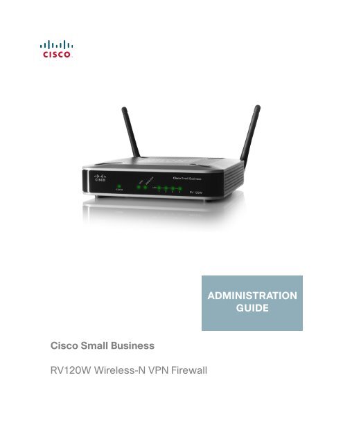
Cisco Small Business RV 120W Wireless-N VPN Firewall ...
Cisco Small Business RV 120W Wireless-N VPN Firewall ...
Cisco Small Business RV 120W Wireless-N VPN Firewall ...

You also want an ePaper? Increase the reach of your titles
YUMPU automatically turns print PDFs into web optimized ePapers that Google loves.
ADMINISTRATIONGUIDE<strong>Cisco</strong> <strong>Small</strong> <strong>Business</strong><strong>RV</strong><strong>120W</strong> <strong>Wireless</strong>-N <strong>VPN</strong> <strong>Firewall</strong>
Revised June 2011<strong>Cisco</strong> and the <strong>Cisco</strong> Logo are trademarks of <strong>Cisco</strong> Systems, Inc. and/or its affiliates in the U.S. and other countries. A listing of <strong>Cisco</strong>'s trademarks can be foundat www.cisco.com/go/trademarks. Third party trademarks mentioned are the property of their respective owners. The use of the word partner does not implya partnership relationship between <strong>Cisco</strong> and any other company. (1005R)© 2011 <strong>Cisco</strong> Systems, Inc. All rights reserved. 78-19307-02
ContentsChapter 2: Configuring Networking 19Configuring the WAN (Internet) Settings 19Configuring the IPv4 WAN (Internet) 20Configuring Automatic Configuration (DHCP) 20Configuring Static IP 21Configuring PPPoE 21Configuring PPTP 22Configuring L2TP 23Configuring MTU Settings 24Configuring the MAC Address 24Configuring PPPoE Profiles 25Configuring the LAN (Local Network) Settings 27Configuring IPv4 LAN (Local Network) Settings 27Configuring the Host Name 27Configuring the IP Address 27Configuring DHCP 28Configuring the DNS Proxy 29Configuring Virtual LAN (VLAN) Membership 30Enabling VLANs 30Creating a VLAN 30Configuring Multiple VLAN Subnets 31Configuring Static DHCP 32Configuring Advanced DHCP Settings 33Configuring Automatic Configuration Download 33Adding a DHCP Client to Configuration File Map 34Viewing DHCP Leased Clients 34Configuring Routing 34Choosing the Routing Mode 34Viewing Routing Information 35Configuring Static Routes 37Configuring Dynamic Routing 38Configuring Port Management 40Configuring Dynamic DNS (DDNS) 40<strong>Cisco</strong> <strong>RV</strong><strong>120W</strong> Administration Guide 2
ContentsConfiguring IPv6 42Configuring the IP Mode 42Configuring IPv6 WAN Settings 42Configuring DHCPv6 42Configuring a Static IP Address 43Configuring IPv6 LAN Properties 43Configuring IPv6 Address Pools 45Configuring IPv6 Routing 45Configuring Dynamic Routing 45Configuring Static Routing 46Configuring Tunneling 47Viewing IPv6 Tunnel Information 47Configuring Intra-Site Automatic Tunnel AddressingProtocol (ISATAP) Tunnels 48Configuring Router Advertisement 49Configuring Router Advertisement Prefixes 50Chapter 3: Configuring the <strong>Wireless</strong> Network 51A Note About <strong>Wireless</strong> Security 51<strong>Wireless</strong> Security Tips 52General Network Security Guidelines 53Understanding the <strong>Cisco</strong> <strong>RV</strong><strong>120W</strong>’s <strong>Wireless</strong> Networks 54Configuring Basic <strong>Wireless</strong> Settings 54Configuring Radio, Mode, and Channel Settings 54Configuring <strong>Wireless</strong> Security and Other Settings 55Configuring Security 56Configuring MAC Filtering 58Configuring Wi-Fi Multimedia 59Configuring <strong>Wireless</strong> Network (SSID) Scheduling 60Configuring Advanced <strong>Wireless</strong> Settings 61Configuring Wi-Fi Protected Setup 62Configuring a <strong>Wireless</strong> Distribution System (WDS) 63<strong>Cisco</strong> <strong>RV</strong><strong>120W</strong> Administration Guide 3
ContentsChapter 4: Configuring the <strong>Firewall</strong> 65<strong>Cisco</strong> <strong>RV</strong><strong>120W</strong> <strong>Firewall</strong> Features 65Configuring Access Rules 67Configuring the Default Outbound Policy 67Creating an Access Rule 67Configuring Attack Prevention 71Configuring Content Filtering 72Enabling Content Filtering 72Blocking Web Components 73Adding Trusted Domains 74Configuring URL Blocking 74Configuring Port Triggering 75Configuring Port Forwarding 76Configuring a DMZ Host 80Configuring Advanced <strong>Firewall</strong> Settings 80Configuring One-to-One Network Address Translation (NAT) 80Configuring MAC Address Filtering 81Configuring IP/MAC Address Binding 82Creating Custom Services 83Creating <strong>Firewall</strong> Schedules 84Configuring Sessions 84Configuring Internet Group Management Protocol (IGMP) 85Configuring LAN (Local Network) Groups 86Enabling Session Initiation Protocol Application-Level Gateway (SIP ALG) 87<strong>Firewall</strong> Configuration Examples 87Chapter 5: Configuring Virtual Private Networks (<strong>VPN</strong>s) and Security 92Configuring <strong>VPN</strong>s 92Creating <strong>Cisco</strong> Quick<strong>VPN</strong> Client Users 93<strong>Cisco</strong> <strong>RV</strong><strong>120W</strong> Administration Guide 4
ContentsConfiguring a Basic <strong>VPN</strong> 93Viewing the Default <strong>VPN</strong> Settings 94Configuring Advanced <strong>VPN</strong> Parameters 94Configuring IKE Policies 95Configuring <strong>VPN</strong> Policies 98Configuring <strong>VPN</strong> Clients 103Monitoring <strong>VPN</strong> Tunnel Status 104Configuring <strong>VPN</strong> Users 105Configuring a PPTP Server 105Adding New <strong>VPN</strong> Users 106Configuring <strong>VPN</strong> Passthrough 106Configuring Security 107Using Certificates for Authentication 107Generating New Certificates 108Importing a Certificate from a File 108Exporting the Router’s Current Certificate 109Using the <strong>Cisco</strong> <strong>RV</strong><strong>120W</strong> With a RADIUS Server 109Configuring 802.1x Port-Based Authentication 110Chapter 6: Configuring Quality of Service (QoS) 112Configuring WAN QoS Profiles 112Configuring Profile Binding 114Configuring CoS Settings 115Mapping CoS Settings to DSCP Values 116Chapter 7: Administering Your <strong>Cisco</strong> <strong>RV</strong><strong>120W</strong> 117Configuring Password Rules 118Using the Management Interface 118Configuring Web Access 119Configuring Remote Management 119Configuring User Accounts 120Setting the Session Timeout Value 120<strong>Cisco</strong> <strong>RV</strong><strong>120W</strong> Administration Guide 5
ContentsConfiguring Network Management 121Configuring SNMP 121Editing SNMPv3 Users 121Adding SNMP Traps 122Configuring Access Control Rules 122Configuring Additional SNMP Information 123Configuring the WAN Traffic Meter 123Using Network Diagnostic Tools 125Using PING 125Using Traceroute 125Performing a DNS Lookup 126Capturing and Tracing Packets 126Configuring Logging 126Configuring Logging Policies 127Configuring <strong>Firewall</strong> Logs 127Configuring Remote Logging 128Configuring Email Logging 129Configuring the Discovery Settings 130Configuring Bonjour 130Configuring UPnP 131Configuring Time Settings 132Backing Up and Restoring the System 132Upgrading Firmware 134Rebooting the <strong>Cisco</strong> <strong>RV</strong><strong>120W</strong> 134Restoring the Factory Defaults 135Chapter 8: Viewing the <strong>Cisco</strong> <strong>RV</strong><strong>120W</strong> Status 136Viewing the Dashboard 136Viewing the System Summary 139Viewing the <strong>Wireless</strong> Statistics 142IPsec Connection Status 143Viewing <strong>VPN</strong> Client Connection Status 144<strong>Cisco</strong> <strong>RV</strong><strong>120W</strong> Administration Guide 6
ContentsViewing Logs 145Viewing Available LAN Hosts 146Viewing Port Triggering Status 147Viewing Port Statistics 148Viewing Open Ports 149Appendix A: Using <strong>Cisco</strong> Quick<strong>VPN</strong> for Windows 7, 2000, XP, or Vista 150Overview 150Before You Begin 150Installing the <strong>Cisco</strong> Quick<strong>VPN</strong> Software 151Installing from the CD-ROM 151Downloading and Installing from the Internet 151Using the <strong>Cisco</strong> Quick<strong>VPN</strong> Software 152Appendix B: Where to Go From Here 154<strong>Cisco</strong> <strong>RV</strong><strong>120W</strong> Administration Guide 7
1IntroductionThis chapter describes the features of the <strong>Cisco</strong> <strong>RV</strong><strong>120W</strong>, guides you through theinstallation process, and gets you started using the Device Manager, a browserbasedutility for configuring the <strong>Cisco</strong> <strong>RV</strong><strong>120W</strong>.• Product Overview, page 1• Getting to Know the <strong>Cisco</strong> <strong>RV</strong><strong>120W</strong>, page 4• Mounting the <strong>Cisco</strong> <strong>RV</strong><strong>120W</strong>, page 6• Connecting the Equipment, page 8• Setting Up the <strong>Cisco</strong> <strong>RV</strong><strong>120W</strong> Using the Setup Wizard, page 12• Using the Getting Started Page, page 13• Navigating through the Pages, page 15• Saving Your Changes, page 17• Viewing the Help Files, page 18• Connecting Devices to Your <strong>Wireless</strong> Network, page 18Product OverviewThank you for choosing the <strong>Cisco</strong> <strong>Small</strong> <strong>Business</strong> <strong>RV</strong><strong>120W</strong> <strong>Wireless</strong>-N <strong>VPN</strong><strong>Firewall</strong>.The <strong>Cisco</strong> <strong>RV</strong><strong>120W</strong> is an advanced Internet-sharing network solution for yoursmall business needs. It allows multiple computers in your office to share anInternet connection through both wired and wireless connections.The <strong>Cisco</strong> <strong>RV</strong><strong>120W</strong> provides a <strong>Wireless</strong>-N access point, combined with supportfor Virtual Private Networks (<strong>VPN</strong>s) to make your network more secure. Its 10/100Ethernet WAN interface connects directly to your broadband DSL or Cablemodem.<strong>Cisco</strong> <strong>RV</strong><strong>120W</strong> Administration Guide 1
IntroductionProduct Overview1LAN Ethernet InterfacesThe <strong>Cisco</strong> <strong>RV</strong><strong>120W</strong> provides four full-duplex 10/100 Ethernet LAN interfaces thatcan connect up to four devices.<strong>Wireless</strong> Access PointThe wireless access point supports the 802.11n standard with MIMO technology,which multiplies the effective data rate. This technology provides betterthroughput and coverage than 802.11g networks.<strong>Firewall</strong> and <strong>VPN</strong> Client AccessThe <strong>Cisco</strong> <strong>RV</strong><strong>120W</strong> incorporates a Stateful Packet Inspection (SPI)-based firewallwith Denial of Service (DoS) prevention and a Virtual Private Network (<strong>VPN</strong>)engine for secure communication between mobile or remote workers and branchoffices.The <strong>Cisco</strong> <strong>RV</strong><strong>120W</strong> supports up to ten gateway-to-gateway IP Security (IPsec)tunnels to facilitate branch office connectivity through encrypted virtual links.Users connecting through a <strong>VPN</strong> tunnel are attached to your company’s networkwith secure access to files, e-mail, and your intranet as if they were in the building.You can also use the <strong>VPN</strong> capability to allow users on your small office network tosecurely connect out to a corporate network<strong>Wireless</strong> Distribution SystemThe <strong>Cisco</strong> <strong>RV</strong><strong>120W</strong>’s wireless access point supports <strong>Wireless</strong> DistributionSystem (WDS), which allows the wireless coverage to be expanded without wires.Virtual NetworksThe access point also supports multiple SSIDs for the use of virtual networks (upto 4 separate virtual networks), with 802.1Q-based VLAN support for trafficseparation.<strong>Cisco</strong> <strong>RV</strong><strong>120W</strong> Administration Guide 2
IntroductionProduct Overview1SecurityThe <strong>Cisco</strong> <strong>RV</strong><strong>120W</strong> implements WPA2-PSK, WPA2-ENT, and WEP encryption,along with other security features including the disabling of SSID broadcasts,MAC-based filtering, and allowing or denying “time of day” access per SSID.Quality of ServiceThe <strong>Cisco</strong> <strong>RV</strong><strong>120W</strong> supports Wi-Fi Multimedia (WMM) and Wi-Fi MultimediaPower Save (WMM-PS) for wireless Quality of Service (QoS). It supports 802.1p,Differentiated Services Code Point (DSCP), and Type of Service (ToS) for wiredQoS, which can improve the quality of your network when using delay-sensitiveVoice over IP (VoIP) applications and bandwidth-intensive video streamingapplications.Configuration and AdministrationWith the <strong>Cisco</strong> <strong>RV</strong><strong>120W</strong>’s embedded web server, you can configure the firewall’ssettings using the browser-based Device Manager. The <strong>Cisco</strong> <strong>RV</strong><strong>120W</strong> supportsInternet Explorer, Firefox, and Safari web browsers.<strong>Cisco</strong> <strong>RV</strong><strong>120W</strong> Administration Guide 3
IntroductionGetting to Know the <strong>Cisco</strong> <strong>RV</strong><strong>120W</strong>1The <strong>Cisco</strong> <strong>RV</strong><strong>120W</strong> also provides a setup wizard. The setup wizard allows you toeasily configure the <strong>Cisco</strong> <strong>RV</strong><strong>120W</strong>’s basic settings.Getting to Know the <strong>Cisco</strong> <strong>RV</strong><strong>120W</strong>Front PanelPOWER—The Power LED lights up green to indicate the device is powered on.Flashes green when the power is coming on or software is being upgraded.WAN LED—The WAN (Internet) LED lights up green when the device is connectedto your cable or DSL modem. The LED flashes green when the device is sendingor receiving data over the WAN port.WIRELESS—The <strong>Wireless</strong> LED lights up green when the wireless module isenabled. The LED is off when the wireless module is disabled. The LED flashesgreen when the device is transmitting or receiving data on the wireless module.LAN—These four LEDs correspond to the four LAN (Ethernet) ports of the <strong>Cisco</strong><strong>RV</strong><strong>120W</strong>. If the LED is continuously lit green, the <strong>Cisco</strong> <strong>RV</strong><strong>120W</strong> is connected to adevice through the corresponding port (1, 2, 3, or 4). The LED for a port flashesgreen when the <strong>Cisco</strong> <strong>RV</strong><strong>120W</strong> is actively sending or receiving data over that port.<strong>Cisco</strong> <strong>RV</strong><strong>120W</strong> Administration Guide 4
IntroductionGetting to Know the <strong>Cisco</strong> <strong>RV</strong><strong>120W</strong>1Back PanelRESET Button—The Reset button has two functions:• If the <strong>Cisco</strong> <strong>RV</strong><strong>120W</strong> is having problems connecting to the Internet, pressthe RESET button for less than five seconds with a paper clip or a pencil tip.This is similar to pressing the reset button on your PC to reboot it.• If you are experiencing extreme problems with the <strong>Cisco</strong> <strong>RV</strong><strong>120W</strong> and havetried all other troubleshooting measures, press and hold in the RESETbutton for 10 seconds. This will restore the factory defaults and clear all ofthe <strong>Cisco</strong> <strong>RV</strong><strong>120W</strong> settings.LAN Ports (1-4)—These ports provide a LAN connection to network devices,such as PCs, print servers, or additional switches.WAN Port—The WAN port is connected to your Internet device, such as a cable orDSL modem.ON/OFF Power Switch—Press this button to turn the <strong>Cisco</strong> <strong>RV</strong><strong>120W</strong> on and off.When the button is pushed in, power is on.Power Port—The power port is where you connect the AC power cable.<strong>Cisco</strong> <strong>RV</strong><strong>120W</strong> Administration Guide 5
IntroductionMounting the <strong>Cisco</strong> <strong>RV</strong><strong>120W</strong>1Mounting the <strong>Cisco</strong> <strong>RV</strong><strong>120W</strong>You can place your <strong>Cisco</strong> <strong>RV</strong><strong>120W</strong> on a desktop or mount it on a wall.Installation Guidelines• Ambient Temperature—To prevent the device from overheating, do notoperate it in an area that exceeds an ambient temperature of104°F (40°C).• Air Flow—Be sure that there is adequate air flow around the device.• Mechanical Loading—Be sure that the device is level and stable to avoidany hazardous conditions.For desktop placement, place the <strong>Cisco</strong> <strong>RV</strong><strong>120W</strong> device horizontally on a flatsurface so that it sits on its four rubber feet.Wall MountingSTEP 1Determine where you want to mount the device and install two screws (notsupplied) that are 2-7/16 in. apart (approximately 61 mm). Mounting screws shouldhave a head that is approximately 5.5 mm in diameter and 2 mm deep, with a shaftthat is at least15.5 mm long and approximately 3.5 mm wide. (Your wall mayrequire shorter or longer screws, or drywall anchors.)Do not mount the screw heads flush with the wall; the screw heads must fit insidethe back of the device.STEP 2With the back panel pointing up (if installing vertically), line up the device so thatthe wall-mount slots on the bottom of the device line up with the two screws.2-7/16Wallmountslots195114<strong>Cisco</strong> <strong>RV</strong><strong>120W</strong> Administration Guide 6
IntroductionMounting the <strong>Cisco</strong> <strong>RV</strong><strong>120W</strong>1STEP 3 Place the wall-mount slots over the screws and slide the device down until thescrews fit snugly into the wall-mount slots.<strong>Cisco</strong> <strong>RV</strong><strong>120W</strong> Administration Guide 7
IntroductionConnecting the Equipment1Connecting the EquipmentBefore you begin the installation, make sure that you have the following equipmentand services:Required• Functional Internet Connection (Broadband DSL or cable modem).• Ethernet cable for WAN (Internet) connection.• PC with functional network adapter (Ethernet connection) to run the SetupWizard or the Device Manager. The Setup Wizard is supported on MicrosoftWindows 2000, Windows XP, Windows Vista, and Windows 7. The DeviceManager is supported on the following web browsers:- Microsoft Internet Explorer 6.0 and later- Mozilla Firefox 3.0 and later- Apple Safari 3.0 or later.• Ethernet cable (provided) to connect the firewall to a PC for configuration.Optional• Uninterruptible Power Supply (UPS) to provide backup power to essentialdevices (strongly recommended).• Ethernet cables for LAN interfaces, if you want to connect additionaldevices to the firewall’s LAN ports.<strong>Cisco</strong> <strong>RV</strong><strong>120W</strong> Administration Guide 8
IntroductionConnecting the Equipment1To connect your firewall to the Internet:STEP 1STEP 2Power off all equipment, including the cable or DSL modem, the PC you will use toconnect to the <strong>RV</strong><strong>120W</strong>, and the <strong>RV</strong><strong>120W</strong>.Use an Ethernet cable to connect the WAN port of the <strong>Cisco</strong> <strong>RV</strong><strong>120W</strong> to yourcable or DSL modem.<strong>Cisco</strong> <strong>RV</strong><strong>120W</strong> Administration Guide 9
IntroductionConnecting the Equipment1STEP 3 Connect one end of a different Ethernet cable to one of the LAN (Ethernet) ports onthe back of the <strong>RV</strong><strong>120W</strong>. (In this example, the LAN 2 port is used.) Connect the otherend of the cable to an Ethernet port on the PC.STEP 4Power on the cable or DSL modem and wait until the connection is active.<strong>Cisco</strong> <strong>RV</strong><strong>120W</strong> Administration Guide 10
IntroductionConnecting the Equipment1STEP 5Connect the power adapter to the <strong>Cisco</strong> <strong>RV</strong><strong>120W</strong> power port (12VDC).!CAUTIONUse only the power adapter that is supplied with the device. Using a differentpower adapter could damage the device.STEP 6Plug the other end of the adapter into an electrical outlet. You may need to use aspecific plug (supplied) for your country.<strong>Cisco</strong> <strong>RV</strong><strong>120W</strong> Administration Guide 11
IntroductionSetting Up the <strong>Cisco</strong> <strong>RV</strong><strong>120W</strong> Using the Setup Wizard1STEP 7 On the <strong>Cisco</strong> <strong>RV</strong><strong>120W</strong>, push in the ON/OFF power button.The power light on the front panel is green when the power adapter is connectedproperly and the unit is turned on.Setting Up the <strong>Cisco</strong> <strong>RV</strong><strong>120W</strong> Using the Setup WizardWith the <strong>RV</strong><strong>120W</strong> powered on and connected to a PC, use the Setup Wizard toconfigure the <strong>Cisco</strong> <strong>RV</strong><strong>120W</strong>.To use the Setup Wizard:STEP 1Start the PC connected to the <strong>RV</strong><strong>120W</strong>.Your computer becomes a DHCP client of the <strong>RV</strong><strong>120W</strong> and receives an IP addressin the 192.168.1.xxx range.STEP 2Launch a web browser and enter 192.168.1.1 in the Address field.This is the default IP address of the <strong>RV</strong><strong>120W</strong>.STEP 3When the login page appears, enter the user name and password.The default user name is admin. The default password is admin. The password iscase sensitive.<strong>Cisco</strong> <strong>RV</strong><strong>120W</strong> Administration Guide 12
IntroductionUsing the Getting Started Page1STEP 4Click Log In.The Setup Wizard starts.STEP 5Follow the Setup Wizard’s on-screen instructions to set up the <strong>RV</strong><strong>120W</strong>.The Setup Wizard tries to automatically detect and configure your connection. If itcannot, the Setup Wizard asks you for information about your Internet connection.If you don not have it, contact your Internet Service Provider (ISP) to obtain thisinformation.During the setup process, the Setup Wizard asks you to enter a new password. Toprotect your firewall from unauthorized access, create a new password that ishard to figure out by others. While you are entering the password, the SetupWizard provides you with instant feedback regarding the strength of thepassword.After the Setup Wizard is done configuring the <strong>RV</strong><strong>120W</strong>, the Getting Startedpage appears. See Using the Getting Started Page, page 13 for moreinformation.Using the Getting Started PageThe Getting Started page displays the most common <strong>Cisco</strong> <strong>RV</strong><strong>120W</strong>configuration tasks. Use the links on this page to jump to the relevant configurationpage.By default, this page appears when you start the Device Manager. However, youcan change this behavior by checking Don’t show this on start up at the bottomof the page.<strong>Cisco</strong> <strong>RV</strong><strong>120W</strong> Administration Guide 13
IntroductionUsing the Getting Started Page1Initial SettingsRun Setup WizardConfigure WAN(Internet) SettingsConfigure LAN(Local Network)SettingsConfigure <strong>Wireless</strong>SettingsClick this link to launch the Setup Wizard.Click this link to open the Internet Setup page.See Configuring the IPv4 WAN (Internet),page 20.Click this link to open the LAN Configuration page.See Configuring IPv4 LAN (Local Network)Settings, page 27.Click this link to open the Basic Settings page.See Configuring Basic <strong>Wireless</strong> Settings,page 54.Add <strong>VPN</strong> Clients See Configuring <strong>VPN</strong> Users, page 105.Quick AccessUpgrade DeviceFirmwareClick this link to open theFirmware Upgrade page.See Upgrading Firmware, page 134.Backup/RestoreSettingsClick this link to open theBackup and Restore page.See Backing Up and Restoring the System,page 132Configure Site to Site<strong>VPN</strong>Configure Web AccessClick this link to open the Basic <strong>VPN</strong> Setup page.See Configuring a Basic <strong>VPN</strong>, page 93.Click this link to open the Web Access page.See Configuring Web Access, page 119.<strong>Cisco</strong> <strong>RV</strong><strong>120W</strong> Administration Guide 14
IntroductionNavigating through the Pages1Device StatusDashboardClick this link to open the Dashboard page.See Viewing the Dashboard, page 136.System SummaryClick this link to open the System Summary page.See Viewing the System Summary, page 139.<strong>Wireless</strong> StatusClick this link to open the <strong>Wireless</strong> Statistics page.See Viewing the <strong>Wireless</strong> Statistics, page 142.<strong>VPN</strong> StatusClick this link to open the IPsec Connection Statuspage.See IPsec Connection Status, page 143.Other ResourcesSupportForumsClick this link to open <strong>Cisco</strong>’s support page.Click this link to visit <strong>Cisco</strong>’s online support forums.Navigating through the PagesUse the navigation tree in the left pane to open the configuration pages.<strong>Cisco</strong> <strong>RV</strong><strong>120W</strong> Administration Guide 15
IntroductionNavigating through the Pages1Click a menu item on the left panel to expand it. Click the menu names displayedunderneath to perform an action or view a sub-menu.<strong>Cisco</strong> <strong>RV</strong><strong>120W</strong> Administration Guide 16
IntroductionSaving Your Changes1Saving Your ChangesWhen you finish making changes on a configuration page, click Save to save thechanges, or click Cancel to undo your changes.<strong>Cisco</strong> <strong>RV</strong><strong>120W</strong> Administration Guide 17
IntroductionViewing the Help Files1Viewing the Help FilesTo view more information about a configuration page, click the Help link near thetop right corner of the page.Connecting Devices to Your <strong>Wireless</strong> NetworkTo connect a device such as a PC or printer to your wireless network, you mustconfigure the wireless connection on the device using the security information youconfigured for the <strong>Cisco</strong> <strong>RV</strong><strong>120W</strong>:• Network name or Service Set Identifier (SSID). The default SSID isciscosb-1.• If applicable, the encryption type and security key.<strong>Cisco</strong> <strong>RV</strong><strong>120W</strong> Administration Guide 18
2Configuring NetworkingThe networking page allows you to configure networking settings. This chaptercontains the following sections:• Configuring the WAN (Internet) Settings, page 19• Configuring the LAN (Local Network) Settings, page 27• Configuring Routing, page 34• Configuring Port Management, page 40• Configuring Dynamic DNS (DDNS), page 40• Configuring IPv6, page 42NOTE<strong>Cisco</strong> recommends you use the Setup Wizard to configure basic networking on the<strong>Cisco</strong> <strong>RV</strong><strong>120W</strong>. You can then make changes and provision advanced features usingthe Device Manager.Configuring the WAN (Internet) SettingsIf you have an IPv4 network, use these sections to configure your network. If youhave an IPv6 network, see Configuring IPv6, page 42.<strong>Cisco</strong> <strong>RV</strong><strong>120W</strong> Administration Guide 19
Configuring NetworkingConfiguring the WAN (Internet) Settings2Configuring the IPv4 WAN (Internet)STEP 1STEP 2Choose Networking > WAN (Internet) > IPV4 WAN (Internet).Choose the type of Internet connection you have. The type of connection you havedetermines the rest of the information you need to enter. See the sections belowfor more information:• Configuring Automatic Configuration (DHCP), page 20• Configuring Static IP, page 21• Configuring PPPoE, page 21• Configuring PPTP, page 22• Configuring L2TP, page 23Configuring Automatic Configuration (DHCP)If your Internet Service Provider (ISP) uses the Dynamic Host ConfigurationProtocol (DHCP) to assign you an IP address, you receive a dynamic IP addressfrom your ISP.To configure DHCP WAN settings:STEP 1STEP 2Choose Networking > WAN (Internet) > IPv4 WAN (Internet).From the Internet Connection Type drop-down menu, chooseAutomatic Configuration - DHCP.STEP 3 Enter MTU information. (See Configuring MTU Settings, page 24.)STEP 4 Enter MAC Address information. (See Configuring the MAC Address, page 24.)STEP 5Click Save.<strong>Cisco</strong> <strong>RV</strong><strong>120W</strong> Administration Guide 20
Configuring NetworkingConfiguring the WAN (Internet) Settings2Configuring Static IPIf your ISP assigned you a permanent IP address, perform the following steps toconfigure your WAN settings:STEP 1STEP 2STEP 3Choose Networking > WAN (Internet) > IPv4 WAN (Internet).From the Internet Connection Type drop-down menu, choose Static IP.Enter this information:IP AddressSubnet maskDefault GatewayPrimary DNS ServerSecondary DNS ServerEnter the IP address of the WAN port.Enter subnet mask of the WAN port.Enter the IP address of the default gateway.Enter the IP address of the primary DNS server.(Optional) Enter the IP address of the secondaryDNS server.STEP 4 Enter MTU information. (See Configuring MTU Settings, page 24.)STEP 5 Enter MAC Address information. (See Configuring the MAC Address, page 24.)STEP 6Click Save.Configuring PPPoEIf you have a Point-to-Point Protocol over Ethernet (PPPoE) connection to theInternet:STEP 1STEP 2STEP 3Choose Networking > WAN (Internet) > IPv4 WAN (Internet).From the Internet Connection Type drop-down menu, choose PPPoE.From the PPPoE Profile Name drop-down menu, choose a PPPoE profile.If no profile is listed, click Configure Profile to create a new profile.To see the details of available profiles, chooseNetworking > WAN (Internet) > PPPoE Profiles. See Configuring PPPoEProfiles, page 25 for more information.STEP 4 Enter MTU information. (See Configuring MTU Settings, page 24.)<strong>Cisco</strong> <strong>RV</strong><strong>120W</strong> Administration Guide 21
Configuring NetworkingConfiguring the WAN (Internet) Settings2STEP 5 Enter MAC Address information. (See Configuring the MAC Address, page 24.)STEP 6Click Save.Configuring PPTPIf you have a Point-to-Point Tunneling Protocol (PPTP) connection to the Internet:STEP 1STEP 2STEP 3Choose Networking > WAN (Internet) > IPv4 WAN (Internet).From the Internet Connection Type drop-down menu, choose PPTP.Enter this information:User NamePasswordMPPE EncryptionConnection TypeEnter your username assigned to you by the ISP.Enter your password assigned to you by the ISP.If your ISP supports Microsoft Point-to-PointEncryption (MPPE), check to enable MPPEencryption.Choose the connection type:• Keep connected—The Internet connection isalways on.• Idle Time—The Internet connection is ononly when traffic is present. If the connectionis idle—that is, no traffic is occurring—theconnection is closed. You might want tochoose this option if your ISP charges basedon connection time.Idle TimeMy IP AddressServer IP AddressIf you choose Idle Time as the connection type,enter the number of minutes after which theconnection terminates. The valid range is 5–999.Enter the IP address assigned to you by your ISP.Enter the IP address of the PPTP server.STEP 4 Enter MTU information. (See Configuring MTU Settings, page 24.)<strong>Cisco</strong> <strong>RV</strong><strong>120W</strong> Administration Guide 22
Configuring NetworkingConfiguring the WAN (Internet) Settings2STEP 5 Enter MAC Address information. (See Configuring the MAC Address, page 24.)STEP 6Click Save.Configuring L2TPIf you have a Layer 2 Tunneling Protocol (L2TP) connection to the Internet:STEP 1STEP 2STEP 3Choose Networking > WAN.From the Internet Connection Type drop-down menu, choose L2TP.Enter this information:User NamePasswordSecretConnection TypeEnter your username assigned to you by the ISP.Enter your password assigned to you by the ISP.(Optional) Enter your secret phrase. This phrase isknown to you and your ISP for use in authenticatingyour logon.Choose the connection type:• Keep connected—The Internet connection isalways on.• Idle Time—The Internet connection is ononly when traffic is present. If the connectionis idle—that is, no traffic is occurring—theconnection is closed. You might want tochoose this option if your ISP charges basedon connection time.Idle TimeMy IP AddressServer IP AddressIf you choose Idle Time as the connection type,enter the number of minutes after which theconnection terminates. The valid range is 5–999.Enter the IP address assigned to you by your ISP.Enter the IP address of the L2TP server.STEP 4 Enter MTU information. (See Configuring MTU Settings, page 24.)<strong>Cisco</strong> <strong>RV</strong><strong>120W</strong> Administration Guide 23
Configuring NetworkingConfiguring the WAN (Internet) Settings2STEP 5 Enter MAC Address information. (See Configuring the MAC Address, page 24.)STEP 6Click Save.Configuring MTU SettingsThe Maximum Transmission Unit (MTU) is the size of the largest packet that can besent over the network. The default MTU value for Ethernet networks is usually1500 bytes and for PPPoE connections, it is 1492 bytes.To configure the MTU settings:STEP 1STEP 2Choose Networking > Choose Networking > WAN (Internet) > IPv4 WAN(Internet).Choose the MTU type:• Default—Unless a change is required by your ISP, we recommend thatyou choose Default in the MTU Type field. The default MTU size is 1500bytes.• Custom—If your ISP requires a custom MTU setting, choose Custom andenter the MTU size in the MTU Size field.STEP 3Click Save.Configuring the MAC AddressThe <strong>Cisco</strong> <strong>RV</strong><strong>120W</strong> has a unique 48-bit local Ethernet hardware address. In mostcases, the default MAC address is used to identify your <strong>Cisco</strong> <strong>RV</strong><strong>120W</strong> to your ISP.However, you can change this setting if required by your ISP.<strong>Cisco</strong> <strong>RV</strong><strong>120W</strong> Administration Guide 24
Configuring NetworkingConfiguring the WAN (Internet) Settings2To configure the MAC address settings:STEP 1STEP 2Choose Networking > WAN (Internet) > IPv4 WAN (Internet).From the Router MAC Address drop-down menu, choose one of these options:• Use Default Address—(Recommended) choose this option to use thedefault MAC address.• Use This Computer's Address—Choose this option to assign the MACaddress of your computer.• Use This MAC—Choose this option if you want to use the MAC address ofthe PC on which you are connecting to the Device Manager.STEP 3Click Save.Configuring PPPoE ProfilesIf you have a PPPoE connection to the Internet, you can create profiles for multiplePPPoE accounts. This can be useful if you connect to the Internet using differentservice provider accounts.STEP 1STEP 2STEP 3Choose Networking > WAN (Internet) > PPPoE Profiles.Click Add to create a new profile.Enter the following information (you may need to contact your ISP to obtain yourPPPoE login information):Profile NameUsernamePasswordEnter the name of the profile.Enter your username assigned to you by the ISP.Enter your password assigned to you by the ISP.<strong>Cisco</strong> <strong>RV</strong><strong>120W</strong> Administration Guide 25
Configuring NetworkingConfiguring the WAN (Internet) Settings2Authentication TypeChoose the authentication type from thedrop-down menu:Auto-negotiate—The server sends a configurationrequest specifying the security algorithm set on it.Then, the <strong>Cisco</strong> <strong>RV</strong><strong>120W</strong> sends backauthentication credentials with the security typesent earlier by the server.PAP—The <strong>Cisco</strong> <strong>RV</strong><strong>120W</strong> uses the PasswordAuthentication Protocol (PAP) to connect to the ISP.CHAP—The <strong>Cisco</strong> <strong>RV</strong><strong>120W</strong> uses the ChallengeHandshake Authentication Protocol (CHAP) whenconnecting with the ISP.MS-CHAP or MS-CHAPv2—The <strong>Cisco</strong> <strong>RV</strong><strong>120W</strong>uses Microsoft Challenge HandshakeAuthentication Protocol when connecting with theISP.Connection TypeChoose the connection type:• Keep connected—The Internet connection isalways on.• Idle Time—The Internet connection is ononly when traffic is present. If the connectionis idle—that is, no traffic is occurring—theconnection is closed. You might want tochoose this option if your ISP charges basedon connection time.Idle TimeIf you choose Idle Time as the connection type,enter the number of minutes after which theconnection terminates. The valid range is 5–999.STEP 4Click Save.The profile is added to the Profile Table.To edit a PPPoE profile listed in the Profile Table, select the profile and click Edit.To delete selected profiles, click Delete.<strong>Cisco</strong> <strong>RV</strong><strong>120W</strong> Administration Guide 26
Configuring NetworkingConfiguring the LAN (Local Network) Settings2Configuring the LAN (Local Network) SettingsIf you have an IPv4 network, use these sections to configure your LAN settings. Ifyou have an IPv6 network, see Configuring IPv6 LAN Properties, page 43.Configuring IPv4 LAN (Local Network) SettingsIf you have an IPv4 LAN, you can configure the following settings:Configuring the Host NameTo configure the host name of the <strong>Cisco</strong> <strong>RV</strong><strong>120W</strong>:STEP 1STEP 2Choose Networking > LAN (Local Network) > IPv4 LAN (Local Network).In the Host Name field, enter the host name of the <strong>Cisco</strong> <strong>RV</strong><strong>120W</strong>. You can useonly alpha-numeric characters and the hyphen.The default hostname (for example, “router9BA120”) consists of the word “router”followed by the last 3 bytes of firewall’s LAN MAC address (in Hex-decimal form).This format allows the FindIT application to use Bonjour to identify <strong>Cisco</strong> <strong>Small</strong><strong>Business</strong> devices on the LAN.STEP 3Click Save.Configuring the IP AddressYou might want to change the default IP address if that address is assigned toanother piece of equipment in your network.<strong>Cisco</strong> <strong>RV</strong><strong>120W</strong> Administration Guide 27
Configuring NetworkingConfiguring the LAN (Local Network) Settings2To configure the IP address of the <strong>Cisco</strong> <strong>RV</strong><strong>120W</strong>:STEP 1STEP 2Choose Networking > LAN (Local Network) > IPv4 LAN (Local Network).Enter this information:IP AddressEnter the LAN IP address of the <strong>RV</strong><strong>120W</strong>.Make sure the address is not in use by anotherdevice on the same network. The default IPaddress is 192.168.1.1.Subnet maskChoose the subnet mask for the new IP addressfrom the drop-down menu. The default subnet is255.255.255.0.STEP 3Click Save.After changing the <strong>Cisco</strong> <strong>RV</strong><strong>120W</strong>’s LAN IP address, your PC is no longerconnected to the <strong>Cisco</strong> <strong>RV</strong><strong>120W</strong>.STEP 4To reconnect your PC to the <strong>Cisco</strong> <strong>RV</strong><strong>120W</strong>:• If DHCP is configured on the <strong>Cisco</strong> <strong>RV</strong><strong>120W</strong>, release and renew your PC’s IPaddress.• If DHCP is not configured on the <strong>Cisco</strong> <strong>RV</strong><strong>120W</strong>, manually assign an IPaddress to your PC. The address must be on the same subnet as the <strong>Cisco</strong><strong>RV</strong><strong>120W</strong>. For example, if you change the <strong>Cisco</strong> <strong>RV</strong><strong>120W</strong>’s IP address to10.0.0.1, assign your PC an IP address in the range of 10.0.0.2 to 10.0.0.254.STEP 5Open a new browser window and enter the new IP address of the <strong>Cisco</strong> <strong>RV</strong><strong>120W</strong>to reconnect.Configuring DHCPBy default, the <strong>Cisco</strong> <strong>RV</strong><strong>120W</strong> functions as a DHCP server to the hosts on the<strong>Wireless</strong> LAN (WLAN) or LAN network and assigns IP and DNS server addresses.With DHCP enabled, the firewall's IP address serves as the gateway address toyour LAN. The PCs in the LAN are assigned IP addresses from a pool ofaddresses. Each address is tested before it is assigned to avoid duplicateaddresses on the LAN.<strong>Cisco</strong> <strong>RV</strong><strong>120W</strong> Administration Guide 28
Configuring NetworkingConfiguring the LAN (Local Network) Settings2For most applications, the default DHCP settings are satisfactory. If you wantanother PC on your network to be the DHCP server, or if you are manuallyconfiguring the network settings of all of your PCs, disable DHCP.To configure the DHCP settings of the <strong>Cisco</strong> <strong>RV</strong><strong>120W</strong>:STEP 1STEP 2Choose Networking > LAN (Local Network) > IPv4 LAN (Local Network).From the DHCP Mode drop-down menu, choose one of these options:• None—Choose this option if the <strong>Cisco</strong> <strong>RV</strong><strong>120W</strong> is not going to act as a DHCPserver.• DHCP Server—Choose this option to configure the <strong>Cisco</strong> <strong>RV</strong><strong>120W</strong> to be aDHCP server and enter this information:- Domain Name— (Optional) Enter the domain name for your network.- Starting IP Address/Ending IP Address—Enter the first and last of thecontiguous addresses in the IP address pool. Any new DHCP clientjoining the LAN is assigned an IP address in this range. You can save partof the range for PCs with fixed addresses. These addresses should be inthe same IP address subnet as the <strong>Cisco</strong> <strong>RV</strong><strong>120W</strong>'s LAN IP address.- Primary DNS Server/Secondary DNS Server—DNS servers mapInternet domain names (for example, www.cisco.com) to IP addresses.Enter the server IP addresses in these fields if you want to use differentDNS servers than are specified in your WAN settings.- Lease time—Enter the duration (in hours) for which IP addresses areleased to clients• DHCP Relay—Choose this option to configure the <strong>Cisco</strong> <strong>RV</strong><strong>120W</strong> to be aDHCP relay agent and enter the address of the relay agent in the RelayGateway field. The relay agent transmits DHCP messages between multiplesubnets.STEP 3Click Save.Configuring the DNS ProxyYou can also enable a DNS proxy. When enabled, the firewall then acts as a proxyfor all DNS requests and communicates with the ISP's DNS servers. Whendisabled, all DHCP clients receive the DNS IP addresses of the ISP.<strong>Cisco</strong> <strong>RV</strong><strong>120W</strong> Administration Guide 29
Configuring NetworkingConfiguring the LAN (Local Network) Settings2To configure the DNS proxy server for the <strong>Cisco</strong> <strong>RV</strong><strong>120W</strong>:STEP 1STEP 2STEP 3Choose Networking > LAN (Local Network) > IPv4 LAN (Local Network).In the DNS Proxy field, check to enable the <strong>Cisco</strong> <strong>RV</strong><strong>120W</strong> to act as a proxy for allDNS requests and communicate with the ISP's DNS servers.Click Save.Configuring Virtual LAN (VLAN) MembershipA VLAN is a group of endpoints in a network that are associated by function orother shared characteristics. Unlike LANs, which are usually geographically based,VLANs can group endpoints without regard to the physical location of theequipment or users.Enabling VLANsSTEP 1STEP 2STEP 3Choose Networking > LAN (Local Network) > VLAN Membership.Check the Enable box.Click Save.Underneath the Enable VLAN field, The VLAN Membership Table is shown. Thisshows available VLANs, including the VLAN ID, description, ports, and whetherinter-VLAN routing is enabled or not for each configured VLAN.Creating a VLANYou can create up to four VLANs on the <strong>Cisco</strong> <strong>RV</strong><strong>120W</strong>.STEP 1STEP 2STEP 3Choose Networking > LAN (Local Network) > VLAN Membership.In the VLAN Membership Table, click Add Row.Enter a numerical VLAN ID that will be assigned to endpoints in the VLANmembership. The VLAN ID can range from 2 to 4094. VLAN ID 1 is reserved for thedefault VLAN, which is used for untagged frames received on the interface, andVLAN ID 4092 is reserved and cannot be used.<strong>Cisco</strong> <strong>RV</strong><strong>120W</strong> Administration Guide 30
Configuring NetworkingConfiguring the LAN (Local Network) Settings2STEP 4STEP 5STEP 6STEP 7Enter a description for the VLAN.To enable routing between this and other VLANS, check the Inter VLAN Routingbox.To enable device management, check the Device Management box. This allowsyou to access the Device Manager from that VLAN. For example, if you created aVLAN with the VLAN ID of 2 and enabled device management, you can access theDevice Manager by using the first IP address on the created VLAN (for example,192.168.2.1).Under each of the ports for the VLAN, choose one of the following:• Tagged—Used when connecting to switches carrying multiple VLANs.• Untagged—Access ports connecting to end devices like printers andworkstations.STEP 8Click Save.Configuring Multiple VLAN SubnetsWhen you create a VLAN, a subnet is created automatically for the VLAN. You canthen further configure the VLAN properties, such as the IP address and DHCPbehavior.To edit a VLAN:STEP 1STEP 2STEP 3Choose Networking > LAN > Multiple VLAN Subnets. The list of subnets appears.Check the box next to the VLAN you want to edit and click Edit.If you want to edit the IP address of this VLAN:a. In the IP address field, enter the new IP address.b. Enter the Subnet Mask for the new IP address.c. Click Save. If you are connected to the <strong>Cisco</strong> <strong>RV</strong><strong>120W</strong> by the LAN port that is amember of this VLAN, you might have to release and renew the IP address onthe PC connected to the LAN port, or manually assign an IP address to your PCthat is in the same subnet as the VLAN. Open a new browser window and reconnectto the <strong>Cisco</strong> <strong>RV</strong><strong>120W</strong>.<strong>Cisco</strong> <strong>RV</strong><strong>120W</strong> Administration Guide 31
Configuring NetworkingConfiguring the LAN (Local Network) Settings2If you want to edit the DHCP behavior of this VLAN:a. In the DHCP Section, in the DHCP Mode field, choose one of the following:• DHCP Server—Choose this to allow the VLAN to act as the DHCP server inthe network. Enter the following information:- Domain Name—Enter the domain name for your network (optional).- Starting and Ending IP Address—Enter the first and last of thecontiguous addresses in the IP address pool. Any new DHCP clientjoining the LAN is assigned an IP address in this range. You can save partof the range for PCs with fixed addresses. These addresses should bein the same IP address subnet as the VLAN’s IP address.- Primary and Secondary DNS Server—DNS servers map Internetdomain names (for example, www.cisco.com) to IP addresses. Enter theserver IP addresses in these fields if you want to use different DNSservers than are specified in your WAN settings.- Lease time—Enter the duration (in hours) for which IP addresses areleased to clients.• DHCP Relay—Choose this if you are using a DHCP relay gateway. The relaygateway transmits DHCP messages between multiple subnets. Enter theaddress of the relay gateway in the Relay Gateway field.• None—Use this to disable DHCP on the VLAN.In the LAN Proxy section, to enable the VLAN to act as a proxy for all DNS requestsand communicate with the ISP's DNS servers, check the Enable box.STEP 4Click Save.Configuring Static DHCPYou can configure a static IP Address and MAC Address for a known computer ordevice on the LAN network from the LAN Interface menu.STEP 1STEP 2STEP 3Choose Networking > LAN (Local Network) > Static DHCP (LAN).Click Add.Enter the IP address of the device.<strong>Cisco</strong> <strong>RV</strong><strong>120W</strong> Administration Guide 32
Configuring NetworkingConfiguring the LAN (Local Network) Settings2STEP 4Enter the MAC address of the device. The format for the MAC Address isXX:XX:XX:XX:XX:XX where X is a number from 0 to 9 (inclusive) or an alphabeticalletter between A and F (inclusive).NOTEThe IP Address assigned should be outside the pool of the DHCP addressesconfigured. The DHCP pool is treated as generic pool and all reserved IPs shouldbe outside this pool. The DHCP server will then serve the reserved IP addresswhen the device using the corresponding MAC address requests an IP address.STEP 5Click Save.Configuring Advanced DHCP SettingsConfiguring Automatic Configuration DownloadYou can configure the <strong>Cisco</strong> <strong>RV</strong><strong>120W</strong> to download a configuration file from a TFTPserver. Upon rebooting, the firewall downloads the file.To configure automatic configuration download:STEP 1STEP 2STEP 3Choose Networking > LAN (Local Network) > Advanced DHCP Configuration.Check Enable to enable downloading of configuration files.Choose the TFTP server type:• Host Name—Enter the host name of the TFTP server in the TFTP server hostname field.• Address—Enter the IP address of the TFTP server in the TFTP Server IPfield.STEP 4Click Save.<strong>Cisco</strong> <strong>RV</strong><strong>120W</strong> Administration Guide 33
Configuring NetworkingConfiguring Routing2Adding a DHCP Client to Configuration File MapThis table displays the list of currently configured DHCP Client MAC address toconfiguration filename mappings. It has the following fields:• MAC Address• Configuration FilenameClick Add to add a new DHCP Client MAC address to configuration filenamemapping. Click Edit to edit the MAC address or boot filename for a particular entry.Click Delete to delete a particular entry.Viewing DHCP Leased ClientsYou can view a list of endpoints on the network (identified by MAC address) andsee the IP address assigned to them by the DHCP server. The VLAN of theendpoint is also displayed.STEP 1STEP 2Choose Networking > LAN > DHCP Leased Clients (LAN).The list of endpoints is displayed; you cannot edit this list.Configuring RoutingChoosing the Routing ModeThe <strong>Cisco</strong> <strong>RV</strong><strong>120W</strong> provides two different routing modes. Network AddressTranslation (NAT), or gateway routing, is a technique that allows several endpointson a LAN to share an Internet connection. The computers on the LAN use a“private” IP address range while the WAN port on the firewall is configured with asingle “public” IP address. The <strong>Cisco</strong> <strong>RV</strong><strong>120W</strong> translates the internal privateaddresses into a public address, hiding internal IP addresses from computers onthe Internet. If your ISP has assigned you a single IP address, you want to use NATso that the computers that connect through the <strong>Cisco</strong> <strong>RV</strong><strong>120W</strong> are assigned IPaddresses from a private subnet (for example, 192.168.10.0).<strong>Cisco</strong> <strong>RV</strong><strong>120W</strong> Administration Guide 34
Configuring NetworkingConfiguring Routing2The other routing mode, “router,” is used if your ISP has assigned you multiple IPaddresses so that you have an IP address for each endpoint on your network. Youmust configure either static or dynamic routes if you use this type of routing. SeeConfiguring Static Routes, page 37, or Configuring Dynamic Routing, page 38.To choose your routing mode:STEP 1STEP 2STEP 3Select Networking > Routing > Routing Mode.Click the box next to the type of routing to configure.Click Save.NOTEIf you have already configured DMZ or firewall settings on your firewall in gateway(NAT) mode, selecting “router” changes those settings back to the default.Viewing Routing InformationTo view routing information your network:STEP 1STEP 2Choose Networking > Routing > Routing Table.Next to the type of network you have, click Display.Information about your network routing is displayed, including the following:IPv4 Routing Table• Destination—Destination host/network IP address for which this route isadded.• Gateway—The gateway used for this route.• Genmask—The netmask for the destination network.• Flags—For debugging purpose only; possible flags include:- UP—Route is up.- Host—Target is a host.<strong>Cisco</strong> <strong>RV</strong><strong>120W</strong> Administration Guide 35
Configuring NetworkingConfiguring Routing2- Gateway—Use gateway.- R—Reinstate route for dynamic routing.- D—Dynamically installed by daemon or redirect.- M—Modified from routing daemon or redirect.- A—Installed by addrconf.- C—Cache entry.- !—Reject route.• Metric—The distance to the target (usually counted in hops).• Ref—Number of references to this route.• Use—Count of lookups for the route. Depending on the use of -F and -C, thisis either route cache misses (-F) or hits (-C).• Interface—Interface to which packets for this route will be sent.• Type—Type of routing used (RIP or static).IPv6 Routing Table• Destination—Destination host/network IP address for which this route isadded.• Next Hop—IP address of an adjacent or intermediate host or router throughwhich traffic must flow before reaching its ultimate destination.• Flags—For debugging purpose only; possible flags include:- UP—Route is up.- Host—Target is a host.- Gateway—Use gateway.- R—Reinstate route for dynamic routing.- D—Dynamically installed by daemon or redirect.- M—Modified from routing daemon or redirect.- A—Installed by addrconf.- C—Cache entry.- !—Reject route.<strong>Cisco</strong> <strong>RV</strong><strong>120W</strong> Administration Guide 36
Configuring NetworkingConfiguring Routing2STEP 7STEP 8STEP 9In the IP Subnet Mask field, enter the IPv4 Subnet Mask for the destination host ornetwork. For Class C IP domains, the Subnet Mask is 255.255.255.0.From the Interface drop-down menu, choose the physical network interfacethrough which this route is accessible (WAN or LAN).In the Gateway IP Address field, enter the IP Address of the gateway throughwhich the destination host or network can be reached. If this firewall is used toconnect your network to the Internet, then your gateway IP is the firewall's IPaddress. If you have another router handling your network's Internet connection,enter the IP address of that router instead.STEP 10 In the Metric field, enter a value between 2 and 15 to define the priority of theroute. If multiple routes to the same destination exist, the route with the lowestmetric is chosen.STEP 11 Click Save.Configuring Dynamic RoutingRIP (Routing Information Protocol, RFC 2453) is an Interior Gateway Protocol (IGP)that is commonly used in internal networks. It allows the <strong>Cisco</strong> <strong>RV</strong><strong>120W</strong> toexchange its routing information automatically with other routers, and allows it todynamically adjust its routing tables and adapt to changes in the network.NOTERIP is disabled by default on the <strong>Cisco</strong> <strong>RV</strong><strong>120W</strong>.To configure dynamic routing:STEP 1STEP 2Choose Networking > Routing > Dynamic Routing.To configure how the firewall sends and receives RIP packets, choose the RIPdirection:• None—The firewall neither broadcasts its route table nor does it accept anyRIP packets from other routers. This option disables RIP.• In Only—The firewall accepts RIP information from other router, but doesnot broadcast its routing table.<strong>Cisco</strong> <strong>RV</strong><strong>120W</strong> Administration Guide 38
Configuring NetworkingConfiguring Routing2• Out Only—The firewall broadcasts its routing table periodically but doesnot accept RIP information from other routers.• Both—The firewall both broadcasts its routing table and also processes RIPinformation received from other routers.STEP 3Choose the RIP version:• Disabled.• RIP-1—This is a class-based routing version that does not include subnetinformation. RIP-1 is the most commonly supported version.• RIP-2B—This version broadcasts data in the entire subnet.• RIP-2M—This version sends data to multicast addresses.STEP 4RIP v2 authentication forces authentication of RIP packets before routes areexchanged with other routers. It acts as a security feature because routes areexchanged only with trusted routers in the network. RIP authentication is disabledby default. You can enter two key parameters so that routes can be exchangedwith multiple routers present in the network. The second key also acts as a failsafewhen authorization with first key fails.To enable authentication for RIP-2B or RIP-2M, check the Enable box. (You mustalso choose the direction as explained in Step 2.)If you enabled RIP v2 authentication, enter the following first and second keyparameters:• MD5 Key ID—Input the unique MD-5 key ID used to create theAuthentication Data for this RIP v2 message.• MD5 Auth Key—Input the auth key for this MD5 key, the auth key that isencrypted and sent along with the RIP-V2 message.• Not Valid Before—Enter the start date when the auth key is valid forauthentication.• Not Valid After—Enter the end date when the auth key is valid forauthentication.STEP 5Click Save.<strong>Cisco</strong> <strong>RV</strong><strong>120W</strong> Administration Guide 39
Configuring NetworkingConfiguring Port Management2Configuring Port ManagementThe <strong>Cisco</strong> <strong>RV</strong><strong>120W</strong> has four LAN ports. You can enable or disable ports, configureif the port is half- or full-duplex, and set the port speed.To configure LAN ports:STEP 1STEP 2STEP 3STEP 4STEP 5STEP 6STEP 7Choose Networking > Port Management.In the Port Management Setting Table, to enable a port, check the Enable box. Todisable the port, uncheck the Enable box. By default, all ports are enabled.Check the Auto Negotiation box to let the firewall and network determine theoptimal port settings. By default, automatic mode is enabled. This setting isavailable only when the Enable box is checked.Check the Flow Control box to enable flow control.(Optional) Choose either half- or full-duplex based on the port support. The defaultis full-duplex for all ports. This setting is available only when the Auto check box isunchecked.(Optional) Select one of the following port speeds: 10 Mbps or 100 Mbps. Thedefault setting is 100 Mbps for all ports. This setting is available only when theAuto check box is unchecked. You can change the port speed if a network isdesigned to run at a particular speed, such as 10 Mbps mode. In this case, theendpoint also uses 10 Mbps mode either by auto-negotiation or manual setting.Click Save.Configuring Dynamic DNS (DDNS)DDNS is an Internet service that allows routers with varying public IP addresses tobe located using Internet domain names. To use DDNS, you must set up an accountwith a DDNS provider such as DynDNS.com or TZO.com.The firewall will notify dynamic DNS servers of changes in the WAN IP address, sothat any public services on your network can be accessed by using the domainname.<strong>Cisco</strong> <strong>RV</strong><strong>120W</strong> Administration Guide 40
Configuring NetworkingConfiguring Dynamic DNS (DDNS)2To configure DDNS:STEP 1STEP 2STEP 3Choose Networking > Dynamic DNS.Select the Dynamic DNS Service you are using. Selecting None disables thisservice.If you selected DynDNS.com:a. Specify the complete Host Name and Domain Name for the DDNS service.b. Enter the DynDNS account username.c. Enter the password for the DynDNS account.d. Check the Use Wildcards box to enable the wildcards feature, which allows allsubdomains of your DynDNS Host Name to share the same public IP as theHost Name. This option can be enabled here if not done on the DynDNS Website.e. In the Update Period field, enter the number of hours before the <strong>Cisco</strong> <strong>RV</strong><strong>120W</strong>updates the host information on DynDNS.com.If you selected TZO.com:a. Specify the complete Host Name and Domain Name for the DDNS service.b. Enter the user e-mail address for the TZO account.c. Enter the user key for the TZO account.d. In the Update Period field, enter the number of hours before the <strong>Cisco</strong> <strong>RV</strong><strong>120W</strong>updates the host information on TZO.com.STEP 4Click Save.<strong>Cisco</strong> <strong>RV</strong><strong>120W</strong> Administration Guide 41
Configuring NetworkingConfiguring IPv62Configuring IPv6If you have an IPv6 network, see the following sections.Configuring the IP ModeTo configure IPv6 properties on the <strong>Cisco</strong> <strong>RV</strong><strong>120W</strong>, set the IP mode to IPv6:STEP 1STEP 2STEP 3Choose Networking > IPv6 > IP Mode.Click the IPv4 and IPv6 Dual-Stack radio button.Click Save.Configuring IPv6 WAN SettingsConfiguring WAN properties for an IPv6 network differs depending on which typeof Internet connection you have. See the sections below for detailed instructions.The <strong>Cisco</strong> <strong>RV</strong><strong>120W</strong> can be configured to be a DHCPv6 client of the ISP for thisWAN or a static IPv6 address provided by the ISP can be assigned.Configuring DHCPv6When the ISP allows you to obtain the WAN IP settings via DHCP, you need toprovide details for the DHCPv6 client configuration.STEP 1STEP 2STEP 3STEP 4Choose IPv6 > IPv6 WAN (Internet).In the WAN (Internet) Address (IPv6) field, choose DHCPv6.Choose if the DHCPv6 client on the gateway is stateless or stateful. If a statefulclient is selected, the gateway connects to the ISP's DHCPv6 server for a leasedaddress. For stateless DHCP, it is not necessary to have a DHCPv6 serveravailable at the ISP. Instead, an ICMPv6 discover message will originate from the<strong>Cisco</strong> <strong>RV</strong><strong>120W</strong> and is used for auto-configuration.Click Save.<strong>Cisco</strong> <strong>RV</strong><strong>120W</strong> Administration Guide 42
Configuring NetworkingConfiguring IPv62Configuring a Static IP AddressIf your ISP assigns you a fixed address to access the Internet, choose this option.The information needed for configuring a static IP address can be obtained fromyour ISP.STEP 1STEP 2STEP 3STEP 4STEP 5STEP 6STEP 7Choose IPv6 > IPv6 WAN (Internet).In the WAN (Internet) Address (IPv6) field, choose Static IPv6.Enter the IPv6 IP address assigned to your firewall.Enter the IPv6 prefix length defined by the ISP. The IPv6 network (subnet) isidentified by the initial bits of the address which are called the prefix (for example,in the IP address 2001:0DB8:AC10:FE01::, 2001 is the prefix). All hosts in thenetwork have identical initial bits for their IPv6 address; the number of commoninitial bits in the network’s addresses is set in this field.Enter the default IPv6 gateway address, or the IP address of the server at the ISPthat this firewall will connect to for accessing the internet.Enter the primary and secondary DNS server IP addresses on the ISP's IPv6network. DNS servers map Internet domain names (for example, www.cisco.com)to IP addresses.Click Save.Configuring IPv6 LAN PropertiesIn IPv6 mode, the LAN DHCP server is enabled by default (similar to IPv4 mode).The DHCPv6 server assigns IPv6 addresses from configured address pools withthe IPv6 Prefix Length assigned to the LAN.To configure IPv6 LAN properties:STEP 1STEP 2STEP 3Choose Networking > IPv6 > IPv6 LAN (Local Area Network).Under LAN TCP/IP Setup, in the IPv6 Address field, enter the IP address of the<strong>Cisco</strong> <strong>RV</strong><strong>120W</strong>. The default IPv6 address for the gateway is fec0::1. You canchange this 128 bit IPv6 address based on your network requirements.Enter the IPv6 prefix length. The IPv6 network (subnet) is identified by the initialbits of the address called the prefix. By default, the prefix is 64 bits long. All hosts<strong>Cisco</strong> <strong>RV</strong><strong>120W</strong> Administration Guide 43
Configuring NetworkingConfiguring IPv62To configure RIPng:STEP 1STEP 2STEP 3Select Networking > IPv6 > Routing.Under RIPng, check Enable.Click Save.Configuring Static RoutingYou can configure static routes to direct packets to the destination network. Astatic route is a pre-determined pathway that a packet must travel to reach aspecific host or network. Some ISPs require static routes to build your routingtable instead of using dynamic routing protocols. Static routes do not require CPUresources to exchange routing information with a peer router. You can also usestatic routes to reach peer routers that do not support dynamic routing protocols.Static routes can be used together with dynamic routes. Be careful not tointroduce routing loops in your network.To create a static route:STEP 1STEP 2STEP 3STEP 4STEP 5STEP 6STEP 7Select Networking > IPv6 > Routing.In the list of static routes, click Add.Enter the route name.If a route is to be immediately active, check the Active box. When a route is addedin an inactive state, it will be listed in the routing table, but will not be used by thefirewall. The route can be enabled later. This feature is useful if the network that theroute connects to is not available when you added the route. When the networkbecomes available, the route can be enabled.In the IPv6 destination field, enter the IPv6 address of the destination host ornetwork for this route.In the IPv6 prefix length field, enter the number of prefix bits in the IPv6 addressthat define the destination subnet.Choose the physical network interface through which this route is accessible:• WAN—The route goes through the WAN interface.• LAN—The route goes through the LAN interface.<strong>Cisco</strong> <strong>RV</strong><strong>120W</strong> Administration Guide 46
Configuring NetworkingConfiguring IPv62• 6 to 4 Tunnel—Uses the tunnel interface to route traffic from an IPv6 networkto other IPv6 networks over an IPv4 network.STEP 8Enter the IP Address of the gateway through which the destination host or networkcan be reached.STEP 9 In the metric field, specify the priority of the route by choosing a value between 2and 15. If multiple routes to the same destination exist, the route with the lowestmetric is used.STEP 10 Click Save.Configuring TunnelingThe <strong>Cisco</strong> <strong>RV</strong><strong>120W</strong> provides several IPv6 tunneling methods. 6to4 tunnelingallows IPv6 packets to be transmitted over an IPv4 network. 6to4 tunneling istypically used when a site or end user wants to connect to the IPv6 Internet usingthe existing IPv4 network.NOTEYou must use static routes when tunneling. See Configuring Static Routing,page 46.To configure 6to4 Tunneling:STEP 1STEP 2STEP 3Select Networking > IPv6 > Tunneling.Check the Automatic Tunneling box.Click Save.Viewing IPv6 Tunnel InformationTo view IPv6 tunnel information, choose Networking > IPv6 > Tunneling. ClickRefresh to get the latest information.The IPv6 Tunnel Status table shows the name of tunnel and the IPv6 address thatis created on the device.<strong>Cisco</strong> <strong>RV</strong><strong>120W</strong> Administration Guide 47
Configuring NetworkingConfiguring IPv62Configuring Intra-Site Automatic Tunnel Addressing Protocol (ISATAP)TunnelsIntra-site automatic tunnel addressing protocol (ISATAP) is a method to transmitIPv6 packets between dual-stack nodes over an IPv4 network. The <strong>Cisco</strong><strong>RV</strong><strong>120W</strong> is one endpoint (a node) for the tunnel. You must also set a local endpoint,as well as the ISATAP Subnet Prefix that defines the logical ISATAP subnet toconfigure a tunnel.To add an ISATAP tunnel:STEP 1STEP 2STEP 3STEP 4STEP 5STEP 6STEP 7Choose Networking > IPv6 > Tunneling.In the ISATAP Tunnel Table, click Add.Enter the tunnel name.Choose the local endpoint address, or the endpoint address for the tunnel thatstarts with the <strong>Cisco</strong> <strong>RV</strong><strong>120W</strong>. The endpoint can be the LAN interface (if the LANis configured as an IPv4 network), or another LAN IPv4 address.If you chose Other IP in Step 4, enter the IPv4 address of the endpoint.Enter the ISATAP subnet prefix. This is the 64-bit subnet prefix that is assigned tothe logical ISATAP subnet for this intranet. This can be obtained from your ISP orinternet registry, or derived from RFC 4193.Click Save.To modify the settings of an ISATAP tunnel:STEP 1STEP 2STEP 3Choose Networking > IPv6 > Tunneling.Check the check boxes for the tunnels you want to modify.Click Edit, make the changes, and click Save.<strong>Cisco</strong> <strong>RV</strong><strong>120W</strong> Administration Guide 48
Configuring NetworkingConfiguring IPv62To delete an ISATAP tunnel:STEP 1STEP 2STEP 3Choose Networking > IPv6 > Tunneling.Check the check boxes for the tunnels you want to delete.Click Delete.Configuring Router AdvertisementThe Router Advertisement Daemon (RADVD) on the <strong>Cisco</strong> <strong>RV</strong><strong>120W</strong> listens forrouter solicitations in the IPv6 LAN and responds with router advertisements asrequired. This is stateless IPv6 auto configuration, and the <strong>Cisco</strong> <strong>RV</strong><strong>120W</strong>distributes IPv6 prefixes to all nodes on the network.To configure the RADVD:STEP 1STEP 2STEP 3Choose Networking > IPv6 > Router Advertisement.Under Router Advertisement Status, choose Enable.Under Advertise Mode, choose one of the following:• Unsolicited Multicast—Select this option to send router advertisements(RAs) to all interfaces belonging to the multicast group.• Unicast only—Select this option to restrict advertisements to well-knownIPv6 addresses only (router advertisements [RAs] are sent to the interfacebelonging to the known address only).STEP 4STEP 5STEP 6If you chose Unsolicited Multicast in Step 3, enter the advertise interval. Theadvertise interval is a random value between the Minimum Router AdvertisementInterval and Maximum Router Advertisement Interval. (MinRtrAdvInterval = 0.33 *MaxRtrAdvInterval.) The default is 30 seconds.Under RA Flags, check Managed to use the administered/stateful protocol foraddress auto configuration. Check Other to use the administered/stateful protocolof other, non-address information auto configuration.Under router preference, choose Low, Medium, or High. The router preferenceprovides a preference metric for default routers. The low, medium and high valuesare signaled in unused bits in Router Advertisement messages. This extension isbackward compatible, both for routers (setting the router preference value) andhosts (interpreting the router preference value). These values are ignored by hosts<strong>Cisco</strong> <strong>RV</strong><strong>120W</strong> Administration Guide 49
Configuring NetworkingConfiguring IPv62that do not implement router preference. This feature is useful if there are otherRADVD-enabled devices on the LAN. The default is high.STEP 7STEP 8STEP 9Enter the MTU size. The MTU is the size of the largest packet that can be sent overthe network. The MTU is used in RAs to ensure all nodes on the network use thesame MTU value when the LAN MTU is not well-known. The default is 1500 bytes.Enter the router lifetime value, or the time in seconds that the advertisementmessages will exist on the route. The default is 3600 seconds.Click Save.Configuring Router Advertisement PrefixesTo configure the RADVD available prefixes:STEP 1STEP 2STEP 3Choose Networking > IPv6 > Advertisement Prefixes.Click Add.Choose the IPv6 Prefix Type:• 6to4—6to4 is a system that allows IPv6 packets to be transmitted over anIPv4 network. It is used when an end user wants to connect to the IPv6Internet using their existing IPv4 connection• Global/Local/ISATAP—By using ISATAP, you can integrate IPv6 traffic into aIPv4 network environment. ISATAP uses a locally assigned IPv4 address tocreate a 64-bit interface identifier for IPv6.STEP 4If you chose 6to4 in Step 3, enter the Site-level aggregation identifier (SLA ID.) TheSLA ID in the 6to4 address prefix is set to the interface ID of the interface on whichthe advertisements are sent.If you chose Global/Local/ISATAP in Step 3, enter the IPv6 prefix and prefix length.The IPv6 prefix specifies the IPv6 network address. The prefix length variable is adecimal value that indicates the number of contiguous, higher-order bits of theaddress that make up the network portion of the address.STEP 5STEP 6Enter the prefix lifetime, or the length of time over which the requesting router isallowed to use the prefix.Click Save.<strong>Cisco</strong> <strong>RV</strong><strong>120W</strong> Administration Guide 50
3Configuring the <strong>Wireless</strong> NetworkThis chapter describes how to configure your wireless network and includes thefollowing sections:• A Note About <strong>Wireless</strong> Security, page 51• Understanding the <strong>Cisco</strong> <strong>RV</strong><strong>120W</strong>’s <strong>Wireless</strong> Networks, page 54• Configuring Basic <strong>Wireless</strong> Settings, page 54• Configuring Advanced <strong>Wireless</strong> Settings, page 61• Configuring Wi-Fi Protected Setup, page 62• Configuring a <strong>Wireless</strong> Distribution System (WDS), page 63A Note About <strong>Wireless</strong> Security<strong>Wireless</strong> networks are convenient and easy to install, so small businesses withhigh-speed Internet access are adopting them at a rapid pace. Because wirelessnetworking operates by sending information over radio waves, it can be morevulnerable to intruders than a traditional wired network. Like signals from yourcellular or cordless phones, signals from your wireless network can also beintercepted. The following information will help you to improve your security:• <strong>Wireless</strong> Security Tips, page 52• General Network Security Guidelines, page 53<strong>Cisco</strong> <strong>RV</strong><strong>120W</strong> Administration Guide 51
Configuring the <strong>Wireless</strong> NetworkA Note About <strong>Wireless</strong> Security3<strong>Wireless</strong> Security TipsSince you cannot physically prevent someone from connecting to your wirelessnetwork, you need to take some additional steps to keep your network secure:• Change the default wireless network name or SSID<strong>Wireless</strong> devices have a default wireless network name or Service SetIdentifier (SSID) set by the factory. This is the name of your wirelessnetwork, and can be up to 32 characters in length.You should change the wireless network name to something unique todistinguish your wireless network from other wireless networks that mayexist around you, but do not use personal information (such as your SocialSecurity number) because this information may be available for anyone tosee when browsing for wireless networks.• Change the default passwordFor wireless products such as access points, routers, and gateways, youwill be asked for a password when you want to change their settings. Thesedevices have a default password set by the factory. The default passwordis often admin. Hackers know these defaults and may try to use them toaccess your wireless device and change your network settings. To thwartany unauthorized changes, customize the device’s password so it will behard to guess.• Enable MAC address filtering<strong>Cisco</strong> routers and gateways give you the ability to enable Media AccessControl (MAC) address filtering. The MAC address is a unique series ofnumbers and letters assigned to every networking device. With MACaddress filtering enabled, wireless network access is provided solely forwireless devices with specific MAC addresses. For example, you canspecify the MAC address of each computer in your network so that onlythose computers can access your wireless network.<strong>Cisco</strong> <strong>RV</strong><strong>120W</strong> Administration Guide 52
Configuring the <strong>Wireless</strong> NetworkA Note About <strong>Wireless</strong> Security3• Enable encryptionEncryption protects data transmitted over a wireless network. Wi-FiProtected Access (WPA/WPA2) and Wired Equivalency Privacy (WEP) offerdifferent levels of security for wireless communication. Currently, devicesthat are Wi-Fi certified are required to support WPA2, but are not requiredto support WEP.A network encrypted with WPA/WPA2 is more secure than a networkencrypted with WEP, because WPA/WPA2 uses dynamic key encryption.To protect the information as it passes over the airwaves, you should enablethe highest level of encryption supported by your network equipment.WEP is an older encryption standard and may be the only option availableon some older devices that do not support WPA.• Keep wireless routers, access points, or gateways away from exterior wallsand windows.• Turn wireless routers, access points, or gateways off when they are notbeing used (at night, during vacations).• Use strong passphrases that are at least eight characters in length.Combine letters and numbers to avoid using standard words that can befound in the dictionary.General Network Security Guidelines<strong>Wireless</strong> network security is useless if the underlying network is not secure. <strong>Cisco</strong>recommends that you take the following precautions:• Password protect all computers on the network and individually passwordprotect sensitive files.• Change passwords on a regular basis.• Install anti-virus software and personal firewall software.• Disable file sharing (peer-to-peer). Some applications may open file sharingwithout your consent and/or knowledge.<strong>Cisco</strong> <strong>RV</strong><strong>120W</strong> Administration Guide 53
Configuring the <strong>Wireless</strong> NetworkUnderstanding the <strong>Cisco</strong> <strong>RV</strong><strong>120W</strong>’s <strong>Wireless</strong> Networks3Understanding the <strong>Cisco</strong> <strong>RV</strong><strong>120W</strong>’s <strong>Wireless</strong> NetworksThe <strong>Cisco</strong> <strong>Small</strong> <strong>Business</strong> <strong>RV</strong> <strong>120W</strong> <strong>Wireless</strong>-N <strong>VPN</strong> <strong>Firewall</strong> provides fourseparate virtual wireless networks. These networks can be configured andenabled with individual settings. You can set up the multiple networks to segmentthe network traffic, to allow different levels of access, such as guest access, or toallow access for different functions such as accounting, billing, and so on.Configuring Basic <strong>Wireless</strong> SettingsThe following sections contain information on how to configure basic wirelesssettings on the <strong>Cisco</strong> <strong>RV</strong><strong>120W</strong>. These settings apply to all of the wirelessnetworks.Configuring Radio, Mode, and Channel SettingsSTEP 1STEP 2STEP 3Choose <strong>Wireless</strong> > Basic Settings.In the Radio field, choose Enable to enable wireless functionality for the<strong>Cisco</strong> <strong>RV</strong><strong>120W</strong>. Choosing Disable turns off wireless functionality for the firewall.In the <strong>Wireless</strong> Network Mode field, choose the type of wireless network basedon the devices you have that will connect to the network:• B/G Mixed—Select this mode if you have devices in the network thatsupport 802.11b and 802.11g.• G Only—Select this mode if all devices in the wireless network onlysupport 802.11g.• B/G/N Mixed—Select this mode if you have devices in the network thatsupport 802.11b, 802.11g and 802.11n.• N Only—Select this mode only if all devices in the wireless networksupport 802.11n.STEP 4STEP 5Select the channel bandwidth. Available choices depend on the wireless networkmode chosen in Step 3.The Control Side Band field defines the sideband which is used for the secondaryor extension channel when the AP is operating in 40 Mhz channel width. Chooselower or upper. This field is only available when channel spacing is set to auto. The<strong>Cisco</strong> <strong>RV</strong><strong>120W</strong> Administration Guide 54
Configuring the <strong>Wireless</strong> NetworkConfiguring Basic <strong>Wireless</strong> Settings3signal components above the carrier frequency constitute the upper sideband(USB) and those below the carrier frequency constitute the lower sideband (LSB).STEP 6STEP 7STEP 8The channel field specifies the frequency that the radio uses to transmit wirelessframes. Select a channel from the list of channels or choose auto to let the <strong>Cisco</strong><strong>RV</strong><strong>120W</strong> determine the best channel to use based on the environment noise levelsfor the available channels.In the U-APSD field, choose Enable to enable the Unscheduled Automatic PowerSave Delivery (also referred to as WMM Power Save) feature that allows the radioto conserve power. This feature is disabled by default.Click Save.Configuring <strong>Wireless</strong> Security and Other SettingsAt a minimum, you should edit the default profiles to enable wireless security. SeeA Note About <strong>Wireless</strong> Security, page 51.You can configure wireless security and other settings for each wireless network.To configure wireless settings:STEP 1STEP 2STEP 3Choose <strong>Wireless</strong> > Basic Settings.In the <strong>Wireless</strong> Basic Settings Table, check the box on the left of the wirelessnetwork you want to configure.Click Edit to configure these network properties:a. Enter the SSID name, or the unique name for this wireless network. Include upto 32 characters, using any of the characters on the keyboard. For addedsecurity, you should change the default value to a unique name.b. Check the Broadcast SSID box if you want to allow all wireless clients withinrange to be able to detect this wireless network when they are scanning thelocal area for available networks. Disable this feature if you do not want to makethe SSID known. When this feature is disabled, wireless users can connect toyour wireless network only if they know the SSID (and provide the requiredsecurity credentials).c. Enter the VLAN, or network for this wireless network. (See Chapter 2,Configuring Networking, for more information on VLANs.) Devices connectingto this network are assigned addresses on this VLAN. The default VLAN is 1and if all the devices are on the same network, this can be left unchanged.<strong>Cisco</strong> <strong>RV</strong><strong>120W</strong> Administration Guide 55
Configuring the <strong>Wireless</strong> NetworkConfiguring Basic <strong>Wireless</strong> Settings3d. (Optional) Check the <strong>Wireless</strong> Isolation within SSID box to separate thisnetwork from the other three networks on the <strong>Cisco</strong> <strong>RV</strong><strong>120W</strong>. When thisfeature is enabled, the network can communicate with the <strong>Cisco</strong> <strong>RV</strong><strong>120W</strong>, butnot with any of the other networks.e. In the Max Associated Clients field, enter the maximum number of endpointsthat can connect to this network. The default value is 8. You can change thisnumber if you want to restrict traffic on the network to prevent it from beingoverloaded, for example. The number of clients connected across all fourvirtual access points cannot exceed 100.f. Click Save.Configuring SecuritySTEP 1STEP 2STEP 3STEP 4STEP 5STEP 6Choose <strong>Wireless</strong> > Basic Settings.In the <strong>Wireless</strong> Basic Settings Table, check the box on the left of the wirelessnetwork you want to configure.Click Edit Security Mode to configure security.Select the SSID to configure.Click Enable under <strong>Wireless</strong> Isolation within SSID to separate this network fromthe other three wireless networks on the <strong>Cisco</strong> <strong>RV</strong><strong>120W</strong>. When this feature isenabled, the network can communicate with the <strong>Cisco</strong> <strong>RV</strong><strong>120W</strong>, but not with anyof the other three networks.In the Security field, select the type of security. All devices on this network mustuse the same security mode and settings to work correctly. <strong>Cisco</strong> recommendsusing the highest level of security that is supported by the devices in yournetwork.• Disabled—Any device can connect to the network. Not recommended.• Wired Equivalent Privacy (WEP)— Weak security with a basic encryptionmethod that is not as secure as WPA. WEP may be required if your networkdevices do not support WPA; however, it is not recommended.• Wi-Fi Protected Access (WPA) Personal—WPA is part of the wirelesssecurity standard (802.11i) standardized by the Wi-Fi Alliance and wasintended as an intermediate measure to take the place of WEP while the802.11i standard was being prepared. It supports TKIP/AES encryption. The<strong>Cisco</strong> <strong>RV</strong><strong>120W</strong> Administration Guide 56
Configuring the <strong>Wireless</strong> NetworkConfiguring Basic <strong>Wireless</strong> Settings3personal authentication is the preshared key (PSK) that is an alphanumericpassphrase shared with the wireless peer.• WPA Enterprise—Allows you to use WPA with RADIUS serverauthentication.• WPA2 Personal—WPA2 is the implementation of security standardspecified in the final 802.11i standard. It supports AES encryption and thisoption uses preshared key (PSK) based authentication.• WPA2 Personal Mixed—Allows both WPA and WPA2 clients to connectsimultaneously using PSK authentication.• WPA2 Enterprise—Allows you to use WPA2 with RADIUS serverauthentication.• WPA2 Enterprise Mixed—Allows both WPA and WPA2 clients to connectsimultaneously using RADIUS authentication.The Encryption Type appears based on the type of network you chose in Step 3:• WPA Personal, WPA Enterprise, WPA2 Personal Mixed, WPA2 EnterpriseMixed—TKIP+AES• WPA2 Personal, WPA2 Enterprise—AESSTEP 7If you chose WEP:a. In the Authentication field, choose Open System or Shared Key. If you chooseOpen System, a wireless client doesn't need to provide a shared key in order toaccess the wireless network. Any client can associate to the router. If youchoose Shared Key, a wireless client must provide the correct shared key(password) in order to access the wireless network.b. Select the Encryption Type (64- or 128-bit WEP). The larger size keys providestronger encryption, making the key more difficult to crack (for example, 64-bitWEP has a 40-bit key which is less secure than the 128-bit WEP, which has a104-bit key).c. (Optional) In the WEP Passphrase field, enter an alphanumeric phrase (longerthan eight characters for optimal security) and click Generate Key to generatefour unique WEP keys in the WEP Key fields below.d. Select one of the four keys to use as the shared key that devices must have inorder to use the wireless network. If you did not generate a key in Step 7c,enter a key directly into the WEP Key field. The length of the key should be 5ASCII characters (or 10 hexadecimal characters) for 64-bit WEP and 13 ASCII<strong>Cisco</strong> <strong>RV</strong><strong>120W</strong> Administration Guide 57
Configuring the <strong>Wireless</strong> NetworkConfiguring Basic <strong>Wireless</strong> Settings3characters (or 26 hexadecimal characters) for 128-bit WEP. Valid hexadecimalcharacters are “0” to “9” and “A” to “F”.If you chose WPA Personal, WPA2 Personal, or WPA2 Personal Mixed:a. Enter the WPA Key, or password/phrase that will secure the network. Devicesconnecting to the network must use this phrase for authentication.b. If you want to see the password as you are entering it, check the UnmaskPassword box.c. In the Key Renewal field, enter the number of seconds after which the <strong>Cisco</strong><strong>RV</strong><strong>120W</strong> will generate a new key. These keys are internal keys exchangedbetween the <strong>Cisco</strong> <strong>RV</strong><strong>120W</strong> and connected devices. The default value (3600seconds) is usually adequate unless you are experiencing network problems.If you chose WPA Enterprise or WPA2 Enterprise Mixed, no further configuration isrequired.If you chose WPA2 Enterprise, you can check the Pre-Authentication box(optional). Pre-authentication allows wireless clients to quickly switch betweenconnected wireless networks sharing the same security configuration. When awireless client disconnects from a wireless network, a notification is sent to thenetwork, which then sends the pre-authentication info to other wireless networks.STEP 8Click Save.Configuring MAC FilteringYou can use MAC filtering to permit or deny access to the wireless network basedon the MAC (hardware) address of the requesting device. For example, you canenter the MAC addresses of a set of PCs and only allow those PCs to access thenetwork. MAC filtering is configured for each wireless network.STEP 1STEP 2STEP 3STEP 4Choose <strong>Wireless</strong> > Basic Settings.In the <strong>Wireless</strong> Basic Settings Table, check the box on the left of the wirelessnetwork you want to configure.Click Edit MAC Filtering.Choose Enable.<strong>Cisco</strong> <strong>RV</strong><strong>120W</strong> Administration Guide 58
Configuring the <strong>Wireless</strong> NetworkConfiguring Basic <strong>Wireless</strong> Settings3STEP 5Under Connection Control, choose one of the following:• Block following MAC addresses from connecting to wireless network—Blocks MAC addresses specified below from connecting to the wirelessnetwork.• Allow only following MAC addresses to connect to wireless network—Allows only the MAC addresses specified below to connect to the wirelessnetwork.STEP 6STEP 7Enter the MAC addresses of the endpoints to allow or deny. To see a list ofcurrently-connected clients, click <strong>Wireless</strong> Clients List.Click Save.Configuring Wi-Fi MultimediaWi-Fi Multimedia (WMM) is used to prioritize different types of traffic. You canconfigure QoS settings to provide different priority to different applications, users,or data flows, or to guarantee a certain level of performance to a data flow.To configure WMM:STEP 1STEP 2STEP 3STEP 4STEP 5Choose <strong>Wireless</strong> > Basic Settings.In the <strong>Wireless</strong> Basic Settings Table, check the box on the left of the wirelessnetwork you want to configure.Click Edit WMM.In the SSID field, select SSID that clients use to connect to the AP.Check the WMM Enable box to enable WMM based on the IEEE 802.11e standardfor this profile. WMM helps in prioritizing wireless traffic according to four accesscategories:• Voice (highest priority, 4)• Video (high priority, 3)• Best effort (medium priority, 2)• Background (lowest priority, 1)STEP 6In the DSCP to Queue table, for each ingress DSCP, you can choose the outputqueue for the traffic. The Differentiated Services Code Point (DSCP) field identifies<strong>Cisco</strong> <strong>RV</strong><strong>120W</strong> Administration Guide 59
Configuring the <strong>Wireless</strong> NetworkConfiguring Basic <strong>Wireless</strong> Settings3the data packet and the output queue identifies the output queue in which thepacket is transmitted:• Voice (4) or Video (3)—High priority queue, minimum delay. Typically usedto send time-sensitive data such as video and other streaming media.• Best Effort (2)—Medium priority queue, medium throughput and delay. Mosttraditional IP data is sent to this queue.• Background (1)—Lowest priority queue, high throughput. Bulk data thatrequires maximum throughput and is not time-sensitive is typically sent tothis queue (FTP data, for example).If you want to change the output queue for packets marked with a particular DSCP,select the new output queue from the drop-down list.STEP 7Click Save.Configuring <strong>Wireless</strong> Network (SSID) SchedulingYou can configure each of the four available wireless networks on the <strong>Cisco</strong><strong>RV</strong><strong>120W</strong> to be active during certain times of the day. To configure the schedule fora wireless network:STEP 1STEP 2STEP 3STEP 4STEP 5STEP 6STEP 7Choose <strong>Wireless</strong> > Basic Settings.In the <strong>Wireless</strong> Basic Settings Table, check the box on the left of the wirelessnetwork you want to configure.Click Edit SSID Scheduling.Select the wireless network for which you want to create a schedule.Check the Enable box to allow you to create a schedule to make the networkactive during certain times.Enter the start and stop times for the network to be active.Click Save.<strong>Cisco</strong> <strong>RV</strong><strong>120W</strong> Administration Guide 60
Configuring the <strong>Wireless</strong> NetworkConfiguring Advanced <strong>Wireless</strong> Settings3Configuring Advanced <strong>Wireless</strong> SettingsTo configure advanced wireless settings on the <strong>Cisco</strong> <strong>RV</strong><strong>120W</strong>:STEP 1STEP 2STEP 3STEP 4STEP 5STEP 6STEP 7Choose <strong>Wireless</strong> > Advanced Settings.In the Beacon Interval field, enter the time in milliseconds between beacontransmissions. The default interval is 100 milliseconds.In the DTIM Interval field, enter the interval at which the delivery traffic indicationmessage should be sent. A DTIM field is a countdown field informing clients of thenext window for listening to broadcast and multicast messages. When the <strong>Cisco</strong><strong>RV</strong><strong>120W</strong> has buffered broadcast or multicast messages for associated clients, itsends the next DTIM with a DTIM Interval value. Its clients hear the beacons andawaken to receive the broadcast and multicast messages.The default interval is 2beacon intervals.The Request to Send (RTS) Threshold is the packet size, in bytes, that requires theAP to check the transmitting frames to determine if an RTS/Clear to Send (CTS)handshake is required with the receiving client. Using a small value causes RTSpackets to be sent more often, consuming more of the available bandwidth,reducing the apparent throughput of the network packets. The default value is2346, which effectively disables RTS.The Fragmentation Threshold is the maximum length of the frame, in bytes,beyond which packets must be fragmented into two or more frames. Collisionsoccur more often for long frames because while sending them, they occupy thechannel for a longer time. The default value is 2346, which effectively disablesfragmentation. If you experience a high packet error rate, you can slightly increasethe fragmentation threshold; setting the fragmentation threshold too low mayresult in poor network performance. Only minor reduction of the default value isrecommended.Choose the Preamble Mode. The 802.11b standard requires that a preamble beappended to every frame before it is transmitted through the air. The preamblemay be either the traditional “long” preamble, which requires 192 μs fortransmission, or it may be an optional “short” preamble that requires only 96 μs. Along preamble is needed for compatibility with the legacy 802.11 systemsoperating at 1 and 2 Mbps. The default selection is long.Choose the Protection Mode. Select none (the default) to turn off CTS. The CTSto-SelfProtection option enables the CTS-to-Self protection mechanism, which isused to minimize collisions among stations in a mixed 802.11b and 802.11g<strong>Cisco</strong> <strong>RV</strong><strong>120W</strong> Administration Guide 61
Configuring the <strong>Wireless</strong> NetworkConfiguring Wi-Fi Protected Setup3environment. This function boosts the <strong>Cisco</strong> <strong>RV</strong><strong>120W</strong>’s ability to catch all wirelesstransmissions but severely decreases performance.STEP 8STEP 9The Short Retry Limit and Long Retry Limit fields determine the number of timesthe <strong>Cisco</strong> <strong>RV</strong><strong>120W</strong> will reattempt a frame transmission that fails. The limit appliesto both long and short frames of a size less than or equal to the RTS threshold.Click Save.Configuring Wi-Fi Protected SetupYou can configure Wi-Fi Protected Setup (WPS) on the <strong>Cisco</strong> <strong>RV</strong><strong>120W</strong> to allowWPS-enabled devices to more easily connect to the wireless network.STEP 1STEP 2Choose <strong>Wireless</strong> > WPS.In the VAP field, select the wireless network on which you want to enable WPS.The network must use WPA, WPA2, or WPA+WPA2 security.NOTEYou can enable WPS on only one of the four networks, or virtual access points.STEP 3STEP 4Under WPS Status, choose Enable to allow WPS configuration. By default, WPS isdisabled.Click Save.<strong>Cisco</strong> <strong>RV</strong><strong>120W</strong> Administration Guide 62
Configuring the <strong>Wireless</strong> NetworkConfiguring a <strong>Wireless</strong> Distribution System (WDS)3To set up a WPS-enabled device in the network:STEP 1STEP 2Choose <strong>Wireless</strong> > WPS.Choose the WPS setup method:• Setup Using a PIN—In the WPS Setup Method section, in the Station PINfield, enter the personal identification number (PIN) of the device you wantto connect to the network. You must log in to that device to obtain its WPSPIN. Then click Configure via PIN. After clicking this button on the <strong>Cisco</strong><strong>RV</strong><strong>120W</strong>, on the WPS-enabled device, select the necessary option to beginWPS. The device should begin communication with the <strong>Cisco</strong> <strong>RV</strong><strong>120W</strong>.• Setup Using a WPS Button—If the device you want to connect has a WPSbutton, push the button on the device. Then, on the <strong>Cisco</strong> <strong>RV</strong><strong>120W</strong>, clickConfigure via PBC (push button configuration).Configuring a <strong>Wireless</strong> Distribution System (WDS)A <strong>Wireless</strong> Distribution System (WDS) is a system that enables the wirelessinterconnection of access points in a network. It allows a wireless network to beexpanded using multiple access points without the need for a wired backbone tolink them.WDS peers are other access points in the network connected in the WDS. Allbase stations in a WDS must be configured to use the same radio channel, methodof encryption (none, WEP, or WPA) and encryption keys.To configure a WDS:STEP 1STEP 2STEP 3STEP 4Choose <strong>Wireless</strong> > WDS.Check the Enable box to enable WDS in the <strong>Cisco</strong> <strong>RV</strong><strong>120W</strong>.Enter a WPA Key (password) for authentication.Click Save.<strong>Cisco</strong> <strong>RV</strong><strong>120W</strong> Administration Guide 63
Configuring the <strong>Wireless</strong> NetworkConfiguring a <strong>Wireless</strong> Distribution System (WDS)3You can manually add WDS peers that can connect to the <strong>Cisco</strong> <strong>RV</strong><strong>120W</strong>:STEP 1STEP 2In the WDS Peer Table, click Add.Enter the MAC (hardware) address of the WDS peer and click Save.<strong>Cisco</strong> <strong>RV</strong><strong>120W</strong> Administration Guide 64
4Configuring the <strong>Firewall</strong>This chapter contains information about configuring the firewall properties of the<strong>Cisco</strong> <strong>RV</strong><strong>120W</strong> and includes the following sections:• <strong>Cisco</strong> <strong>RV</strong><strong>120W</strong> <strong>Firewall</strong> Features, page 65• Configuring Access Rules, page 67• Configuring Attack Prevention, page 71• Configuring Content Filtering, page 72• Configuring URL Blocking, page 74• Configuring Port Triggering, page 75• Configuring Port Forwarding, page 76• Configuring a DMZ Host, page 80• Configuring Advanced <strong>Firewall</strong> Settings, page 80• <strong>Firewall</strong> Configuration Examples, page 87<strong>Cisco</strong> <strong>RV</strong><strong>120W</strong> <strong>Firewall</strong> FeaturesYou can secure your network by creating and applying access rules that the<strong>Cisco</strong> <strong>RV</strong><strong>120W</strong> uses to selectively block and allow inbound and outbound Internettraffic. You then specify how and to what devices the rules apply. You canconfigure the following:• Services or traffic types (examples: web browsing, VoIP, other standardservices and also custom services that you define) that the router shouldallow or block.• Rules for outbound (from your LAN to the Internet) or inbound (from theInternet to your LAN) traffic.<strong>Cisco</strong> <strong>RV</strong><strong>120W</strong> Administration Guide 65
Configuring the <strong>Firewall</strong><strong>Cisco</strong> <strong>RV</strong><strong>120W</strong> <strong>Firewall</strong> Features4• Schedules as to when the router should apply rules.• Keywords (in a domain name or on a URL of a web page) that the routershould allow or block.• MAC addresses of devices whose inbound access to your network therouter should block.• Port triggers that signal the router to allow or block access to specifiedservices as defined by port number.• Reports and alerts that you want the router to send to you.You can, for example, establish restricted-access policies based on time-of-day,web addresses, and web address keywords. You can block Internet access byapplications and services on the LAN, such as chat rooms or games. You can blockjust certain groups of PCs on your network from being accessed by the WAN orpublic network.Inbound (Internet to LAN) rules restrict access to traffic entering your network,selectively allowing only specific outside users to access specific local resources.By default, all access from the insecure WAN side is blocked from accessing thesecure LAN, except in response to requests from the LAN or DMZ. To allowoutside devices to access services on the secure LAN, you must create a firewallrule for each service.If you want to allow incoming traffic, you must make the router's WAN port IPaddress known to the public. This is called “exposing your host.” How you makeyour address known depends on how the WAN ports are configured; for the<strong>Cisco</strong> <strong>RV</strong><strong>120W</strong>, you may use the IP address if a static address is assigned to theWAN port, or if your WAN address is dynamic, a DDNS (Dynamic DNS) name canbe used.Outbound (LAN to Internet) rules restrict access to traffic leaving your network,selectively allowing only specific local users to access specific outside resources.The default outbound rule is to allow access from the secure zone (LAN) to theinsecure WAN. To block hosts on the secure LAN from accessing services on theoutside (insecure WAN), you must create a firewall rule for each service.<strong>Cisco</strong> <strong>RV</strong><strong>120W</strong> Administration Guide 66
Configuring the <strong>Firewall</strong>Configuring Access Rules4Configuring Access RulesConfigure access rules to control traffic to and from your network. To configureaccess rules, choose <strong>Firewall</strong> > Access Rules. All configured firewall rules on the<strong>Cisco</strong> <strong>RV</strong><strong>120W</strong> are displayed in the Access Rule Table.Configuring the Default Outbound PolicyYou can configure the default outbound policy for the traffic that is directed fromyour secure network (LAN) to the Internet. The default inbound policy for trafficflowing from the Internet to your LAN is always blocked and cannot be changed.The default outbound policy applies to traffic that is not covered by the specificfirewall rules that you have configured. For example, you may have specificfirewall rules restricting outbound instant messaging and video traffic, but all othertraffic would be permitted if you choose allow as the default outbound policy.To configure the default outbound policy:STEP 1STEP 2STEP 3Choose <strong>Firewall</strong> > Access Rules.Under Default Outbound Policy, choose Allow or Block. Allow permits traffic fromyour LAN to the Internet. Block does not permit traffic from your LAN to theInternet.Click Save.Creating an Access RuleAccess rules specify the type of traffic that is allowed into and out of yournetwork. To create access rules:STEP 1STEP 2STEP 3Choose <strong>Firewall</strong> > Access Rules.Click Add Rule.Under Connection Type, choose the destination of traffic covered by this rule:• Inbound—Traffic from the Internet (WAN) to your network (LAN)• Outbound—Traffic from your network (LAN) to the Internet (WAN)<strong>Cisco</strong> <strong>RV</strong><strong>120W</strong> Administration Guide 67
Configuring the <strong>Firewall</strong>Configuring Access Rules4STEP 4Choose the action:• Always Block—Always block the selected type of traffic.• Always Allow—Never block the selected type of traffic.• Block by schedule, otherwise allow—Blocks the selected type of trafficaccording to a schedule. Choose the schedule from the drop-down list. SeeCreating <strong>Firewall</strong> Schedules, page 84.• Allow by schedule, otherwise block—Allows the selected type of trafficaccording to a schedule. Choose the schedule from the drop-down list. SeeCreating <strong>Firewall</strong> Schedules, page 84.STEP 5Choose the service to allow or block for this rule. Choose Any Traffic to allow therule to apply to all applications and services, or you can choose a singleapplication to block:• AIM (AOL Instant Messenger)• BGP (Border Gateway Control)• BOOTP_CLIENT (Bootstrap Protocol client)• BOOTP_SE<strong>RV</strong>ER (Bootstrap Protocol server)• CU-SEEME (videoconferencing) UDP or TCP• DNS (Domain Name System), UDP or TCP• FINGER• FTP (File Transfer Protocol)• HTTP (Hyptertext Transfer Protocol)• HTTPS (Secure Hypertext Transfer Protocol)• ICMP (Internet Control Message Protocol) type 3 through 11 or 13• ICQ (chat)• IMAP (Internet Message Access Protocol) 2 or 3• IRC (Internet Relay Chat)• NEWS• NFS (Network File System)• NNTP (Network News Transfer Protocol)<strong>Cisco</strong> <strong>RV</strong><strong>120W</strong> Administration Guide 68
Configuring the <strong>Firewall</strong>Configuring Access Rules4• PING• POP3 (Post Office Protocol)• PPTP (Point-to-Point Tunneling Protocol)• RCMD (command)• REAL-AUDIO• REXEC (Remote execution command)• RLOGIN (Remote login)• RTELNET (Remote telnet)• RTSP (Real-Time Streaming Protocol) TCP or UDP• SFTP (Secure Shell File Transfer Protocol)• SMTP (Simple Mail Transfer Protocol)• SNMP (Simple Network Management Protocol) TCP or UDP• SNMP-TRAPS (TCP or UDP)• SQL-NET (Structured Query Language)• SSH (TCP or UDP)• STRMWORKS• TACACS (Terminal Access Controller Access-Control System)• TELNET (command)• TFTP (Trivial File Transfer Protocol)• RIP (Routing Information Protocol)• IKE• SHTTPD (Simple HTTPD web server)• IPSEC-UDP-ENCAP (UDP Encapsulation of IPsec packets)• IDENT protocol• VDOLIVE (live web video delivery)• SSH (secure shell)• SIP-TCP or SIP-UDP<strong>Cisco</strong> <strong>RV</strong><strong>120W</strong> Administration Guide 69
Configuring the <strong>Firewall</strong>Configuring Access Rules4STEP 6In the Source IP field, configure the IP address to which the firewall rule applies:• Any—The rule applies to traffic originating from any IP address in the localnetwork.• Single Address—The rule applies to traffic originating from a single IPaddress in the local network. Enter the address in the Start field.• Address Range—The rule applies to traffic originating from an IP addresslocated in a range of addresses. Enter the starting IP address in the Startfield, and the ending IP address in the Finish field.STEP 7If you are configuring an inbound firewall access rule:a. Destination Network Address Translation (DNAT) maps a public IP address(your dedicated WAN address) to an IP address on your private network. In theSend to Local Server (DNAT IP) field, specify an IP address of a machine on theLocal Network which is hosting the server.b. The router supports multi-NAT, so your Internet Destination IP address does nothave to be the address of your WAN. On a single WAN interface, multiple publicIP addresses are supported. If your ISP assigns you more than one public IPaddress, one of these can be used as your primary IP address on the WANport, and the others can be assigned to servers on the LAN. In this way, theLAN can be accessed from the internet by its aliased public IP address. Checkthe Enable box and enter the IP address you want to use.c. Under Rule Status, choose Enabled or Disabled. You may want to configure arule and choose Disabled if you want to enable it at a later time.If you are configuring an outbound firewall access rule:a. In the Destination IP field, configure the IP address to which the firewall ruleapplies:• Any—The rule applies to traffic going to any IP address.• Single Address—The rule applies to traffic going to a single IP address.Enter the address in the Start field.• Address Range—The rule applies to traffic going to an IP address locatedin a range of addresses. Enter the starting IP address in the Start field, andthe ending IP address in the Finish field.b. You can configure Secure Network Address Translation (SNAT) to map a publicIP address (your Dedicated WAN address, Optional WAN address, or anotheraddress) to an IP address on your private network. Under Use This SNAT IPAddress, check Enable and enter the SNAT IP Address.<strong>Cisco</strong> <strong>RV</strong><strong>120W</strong> Administration Guide 70
Configuring the <strong>Firewall</strong>Configuring Attack Prevention4c. Under Rule Status, choose Enabled or Disabled. You may want to configure arule and choose Disabled if you want to enable it at a later time.Configuring Attack PreventionAttacks are malicious security breaches or unintentional network issues thatrender the <strong>Cisco</strong> <strong>RV</strong><strong>120W</strong> unusable. Attack prevention allows you to manage WANsecurity threats such as continual ping requests and discovery via ARP scans.TCP and UDP flood attack prevention can be enabled to manage extreme usageof WAN resources.As well, certain Denial-of-Service (DoS) attacks can be blocked. These attacks, ifuninhibited, can use up processing power and bandwidth and prevent regularnetwork services from running normally. ICMP packet flooding, SYN trafficflooding, and Echo storm thresholds can be configured to temporarily suspendtraffic from the offending source.To configure attack prevention:STEP 1STEP 2Choose <strong>Firewall</strong> > Attack Prevention.Check the boxes to enable the following functions:WAN (Internet) Security Checks• Respond to Ping on WAN (Internet)—To configure the <strong>Cisco</strong> <strong>RV</strong><strong>120W</strong> toallow a response to an Internet Control Message Protocol (ICMP) Echo(ping) request on the WAN interface, check this box. This setting is used asa diagnostic tool for connectivity problems. Not enabled by default.• Stealth Mode—If Stealth Mode is enabled, the router will not respond toport scans from the WAN. This feature makes the network less susceptibleto discovery and attacks. Enabled by default.• Flood— If this option is enabled, the router will drop all invalid TCP packets.This feature protects the network from a SYN flood attack. Enabled bydefault.<strong>Cisco</strong> <strong>RV</strong><strong>120W</strong> Administration Guide 71
Configuring the <strong>Firewall</strong>Configuring Content Filtering4LAN (Local Network) Security Checks• Block UDP Flood—If this option is enabled, the router will not accept morethan 25 simultaneous, active UDP connections from a single computer onthe LAN. Enabled by default.ICSA (International Computer Security Association) Settings• Block Anonymous ICMP Messages—ICSA requires the firewall to silentlyblock without sending an ICMP notification to the sender. Some protocols,such as MTU Path Discovery, require ICMP notifications. Enable this settingto operate in “stealth” mode. Enabled by default.• Block Fragmented Packets—ICSA requires the firewall to block fragmentedpackets from ANY to ANY. Enabled by default.• Block Multicast Packets—ICSA requires the firewall to block multicastpackets. Enabled by default.STEP 3Click Save.Configuring Content FilteringThe <strong>Cisco</strong> <strong>RV</strong><strong>120W</strong> supports several content filtering options. You can blockcertain web applications or components (such as ActiveX or Java). You can set uptrusted domains from which to always allow content. You can block access toInternet sites by specifying keywords to block. If these keywords are found in thesite's name (for example, web site URL or newsgroup name), the site is blocked.You also need to turn on content filtering to set up trusted domains.Enabling Content FilteringTo enable content filtering:STEP 1STEP 2STEP 3Choose <strong>Firewall</strong> > Content Filtering.Check the Enable box.Click Save.<strong>Cisco</strong> <strong>RV</strong><strong>120W</strong> Administration Guide 72
Configuring the <strong>Firewall</strong>Configuring Content Filtering4Blocking Web ComponentsCertain commonly-used web components can be blocked for increased security.Some of these components can be used by malicious websites to infectcomputers that access them.STEP 1STEP 2Choose <strong>Firewall</strong> > Content Filtering.With content filtering enabled, under Web Components, select the check box foreach component you wish to block:• Proxy—A proxy server (or simply, proxy) allows computers to routeconnections to other computers through the proxy, thus circumventingcertain firewall rules. For example, if connections to a specific IP addressare blocked by a firewall rule, the requests can be routed through a proxythat is not blocked by the rule, rendering the restriction ineffective. Enablingthis feature blocks proxy servers.• Java—Blocks java applets from being downloaded from pages that containthem. Java applets are small programs embedded in web pages thatenable dynamic functionality of the page. A malicious applet can be used tocompromise or infect computers. Enabling this setting blocks Java appletsfrom being downloaded.• ActiveX—Similar to Java applets, ActiveX controls are installed on aWindows computer while running Internet Explorer. A malicious ActiveXcontrol can be used to compromise or infect computers. Enabling thissetting blocks ActiveX applets from being downloaded.• Cookies—Cookies are used to store session information by websites thatusually require login. However, several websites use cookies to storetracking information and browsing habits. Enabling this option filters outcookies from being created by a website.NOTEMany websites require that cookies be accepted in order for the site to beaccessed properly. Blocking cookies can cause many websites to not functionproperly.STEP 3Click Save.<strong>Cisco</strong> <strong>RV</strong><strong>120W</strong> Administration Guide 73
Configuring the <strong>Firewall</strong>Configuring URL Blocking4Adding Trusted DomainsYou can add a list of trusted domains. These domains are bypassed duringkeyword filtering. For example, if “yahoo” is added to the blocked keywords listand www.yahoo.com is added to the trusted domain list, then www.yahoo.comwill be allowed, but mail.yahoo.com will not be allowed.NOTEBefore adding trusted domains, you must enable content filtering. See EnablingContent Filtering, page 72.To add trusted domains:STEP 1STEP 2STEP 3Choose <strong>Firewall</strong> > Content Filtering. The Trusted Domain Table displays a list ofcurrently configured trusted domains.Click Add and enter the name of the trusted domain.Click Save.Configuring URL BlockingYou can block access to websites that contain specific keywords in the URL orpage contents. To configure URL blocking:STEP 1STEP 2STEP 3STEP 4STEP 5STEP 6Choose <strong>Firewall</strong> > URL Blocking. The table displays currently blocked keywords.Click Add Row.Under Status, check the box to enable blocking for the new keyword.Select the group to which to apply the keyword blocking. If you need to configurea new group, click Configure LAN Groups. (See Configuring LAN (LocalNetwork) Groups, page 86.)Enter the keyword to block.Click Save.<strong>Cisco</strong> <strong>RV</strong><strong>120W</strong> Administration Guide 74
Configuring the <strong>Firewall</strong>Configuring Port Triggering4Configuring Port TriggeringPort triggering allows devices on the LAN to request one or more ports to beforwarded to them. Port triggering waits for an outbound request from the LAN onone of the defined outgoing ports, and then opens an incoming port for thatspecified type of traffic. Port triggering is a form of dynamic port forwarding whilean application is transmitting data over the opened outgoing or incoming ports.Port triggering opens an incoming port for a specific type of traffic on a definedoutgoing port.Port triggering is more flexible than static port forwarding (available whenconfiguring firewall rules) because a rule does not have to reference a specificLAN IP or IP range. Ports are also not left open when not in use, thereby providinga level of security that port forwarding does not offer.NOTE Port triggering is not appropriate for servers on the LAN, since there is adependency on the LAN device making an outgoing connection before incomingports are opened.Some applications require that, when external devices connect to them, theyreceive data on a specific port or range of ports in order to function properly. Therouter must send all incoming data for that application only on the required port orrange of ports. The gateway has a list of common applications and games withcorresponding outbound and inbound ports to open. You can also specify a porttriggering rule by defining the type of traffic (TCP or UDP) and the range ofincoming and outgoing ports to open when enabled.To add a port triggering rule:STEP 1STEP 2STEP 3STEP 4STEP 5STEP 6Choose <strong>Firewall</strong> > Port Triggering.Click Add.Specify an easily-identifiable name for this rule.Check the Enable box to enable the rule.Select whether the port uses TCP, UDP, or both protocols.In the Outgoing (Trigger) Port Range section, specify the port number or range ofport numbers that will trigger this rule when a connection request from outgoing<strong>Cisco</strong> <strong>RV</strong><strong>120W</strong> Administration Guide 75
Configuring the <strong>Firewall</strong>Configuring Port Forwarding4traffic is made. If the outgoing connection uses only one port, then specify thesame port number in the Start Port and End Port fields.STEP 7STEP 8In the Incoming (Response) Port Range section, specify the port number or rangeof port numbers used by the remote system to respond to the request it receives.If the incoming connection uses only one port, then specify the same port numberin the Start Port and End Port fields.Click Save.Configuring Port ForwardingPort forwarding is used to redirect traffic from the Internet from one port on theWAN to another port on the LAN. The port forwarding rules menu allows selectionof a service. Common services are available or you can define a custom serviceand associated ports to forward.The Port Forwarding Rule Table lists all the available port forwarding rules for thisdevice and allows you to configure port forwarding rules. The table contains thefollowing information:• Action—Whether to block or allow traffic (always or by schedule) thatmeets these filter rules, and when the rule is applicable.• Service—Service for which this port forwarding rule is applicable.• Status—A port forwarding rule can be disabled if not in use and enabledwhen needed. The port forwarding rule is disabled if the status is disabledand it is enabled if the status is enabled. Disabling a port forwarding ruledoes not delete the configuration.• Source IP—The source IP address for traffic from which traffic is forwarded(Any, Single Address or Address Range).• Destination IP—The IP address of the server to which traffic is forwarded.• Forward From Port—From which port traffic will be forwarded.• Forward To Port—To which port traffic will be forwarded.<strong>Cisco</strong> <strong>RV</strong><strong>120W</strong> Administration Guide 76
Configuring the <strong>Firewall</strong>Configuring Port Forwarding4To configure port forwarding:STEP 1STEP 2STEP 3Choose <strong>Firewall</strong> > Port Forwarding.Click Add.Choose the action:• Always Block—Always block the selected type of traffic.• Always Allow—Never block the selected type of traffic.• Block by Schedule—Blocks the selected type of traffic according to aschedule. Choose the schedule from the drop-down list. See Creating<strong>Firewall</strong> Schedules, page 84.• Allow by Schedule—Allows the selected type of traffic according to aschedule. Choose the schedule from the drop-down list. See Creating<strong>Firewall</strong> Schedules, page 84.STEP 4Under Service, select one of the common or custom services defined for thisdevice:• AIM (AOL Instant Messenger)• BGP (Border Gateway Control)• BOOTP_CLIENT (Bootstrap Protocol client)• BOOTP_SE<strong>RV</strong>ER (Bootstrap Protocol server)• CU-SEEME (videoconferencing) UDP or TCP• DNS (Domain Name System), UDP or TCP• FINGER• FTP (File Transfer Protocol)• HTTP (Hyptertext Transfer Protocol)• HTTPS (Secure Hypertext Transfer Protocol)• ICMP (Internet Control Message Protocol) type 3 through 11 or 13• ICQ (chat)• IMAP (Internet Message Access Protocol) 2 or 3• IRC (Internet Relay Chat)<strong>Cisco</strong> <strong>RV</strong><strong>120W</strong> Administration Guide 77
Configuring the <strong>Firewall</strong>Configuring Port Forwarding4• NEWS• NFS (Network File System)• NNTP (Network News Transfer Protocol)• PING• POP3 (Post Office Protocol)• PPTP (Point-to-Point Tunneling Protocol)• RCMD (command)• REAL-AUDIO• REXEC (Remote execution command)• RLOGIN (Remote login)• RTELNET (Remote telnet)• RTSP (Real-Time Streaming Protocol) TCP or UDP• SFTP (Secure Shell File Transfer Protocol)• SMTP (Simple Mail Transfer Protocol)• SNMP (Simple Network Management Protocol) TCP or UDP• SNMP-TRAPS (TCP or UDP)• SQL-NET (Structured Query Language)• SSH (TCP or UDP)• STRMWORKS• TACACS (Terminal Access Controller Access-Control System)• TELNET (command)• TFTP (Trivial File Transfer Protocol)• RIP (Routing Information Protocol)• IKE• SHTTPD (Simple HTTPD web server)• IPSEC-UDP-ENCAP (UDP Encapsulation of IPsec packets)• IDENT protocol<strong>Cisco</strong> <strong>RV</strong><strong>120W</strong> Administration Guide 78
Configuring the <strong>Firewall</strong>Configuring Port Forwarding4• VDOLIVE (live web video delivery)• SSH (secure shell)• SIP-TCP or SIP-UDPSTEP 5Select the Source IP:• Any—Specifies that the rule being created is for traffic from the givenendpoint.• Single Address—Limit to one host. Requires the IP address of the host towhich this rule would be applied.• Address Range—This is used to apply this rule to a group of computers/devices within an IP address range. Requires a from IP address and to IPaddress.STEP 6If you chose Single Address in Step 6, enter the IP address in the Start field.If you chose Address Range in Step 6, enter the starting IP address of the range inthe Start field and the ending IP address of the range in the Finish field.STEP 7 If you chose Always Allow, Block by Schedule, or Allow by Schedule in Step 3:a. Enter the Destination IP address, or the address where traffic meeting the ruleshould be sent.b. In the Forward from Port field, choose Same as Incoming Port if the trafficshould be forwarded from the same port number on the outgoing server.Otherwise, choose Specify Port and enter the port number in the Port Numberfield.c. In the Forward to Port field, Choose Same as Incoming Port if the traffic shouldbe sent to the same port on the receiving server. Otherwise, choose SpecifyPort and enter the port number in the Port Number field.STEP 8Click Save.<strong>Cisco</strong> <strong>RV</strong><strong>120W</strong> Administration Guide 79
Configuring the <strong>Firewall</strong>Configuring a DMZ Host4Configuring a DMZ HostThe <strong>Cisco</strong> <strong>RV</strong><strong>120W</strong> supports DMZ options. A DMZ is a sub-network that is open tothe public but behind the firewall. DMZ allows you to redirect packets going toyour WAN port IP address to a particular IP address in your LAN. It isrecommended that hosts that must be exposed to the WAN (such as web or e-mailservers) be placed in the DMZ network. <strong>Firewall</strong> rules can be allowed to permitaccess to specific services and ports to the DMZ from both the LAN or WAN. Inthe event of an attack on any of the DMZ nodes, the LAN is not necessarilyvulnerable as well.You must configure a fixed (static) IP address for the endpoint that will bedesignated as the DMZ host. The DMZ host should be given an IP address in thesame subnet as the router's LAN IP address but it cannot be identical to the IPaddress given to the LAN interface of this gateway.STEP 1STEP 2STEP 3STEP 4Choose <strong>Firewall</strong> > DMZ Host.Check the Enable box to enable DMZ on the network.Enter the IP address for the endpoint that will receive the redirected packets. Thisis the DMZ host.Click Save. You must then configure firewall rules for the zone. See CreatingCustom Services, page 83.Configuring Advanced <strong>Firewall</strong> SettingsThis page allows you to configure many advanced firewall settings.Configuring One-to-One Network Address Translation (NAT)One-to-one NAT is a way to make systems behind a firewall that are configuredwith private IP addresses appear to have public IP addresses.To configure one-to-one NAT, choose <strong>Firewall</strong> > Advanced Settings > One-to-OneNAT. The One-to-One-NAT Rules Table lists the available One-To-One NAT rulesthat have been configured. It displays the following fields:<strong>Cisco</strong> <strong>RV</strong><strong>120W</strong> Administration Guide 80
Configuring the <strong>Firewall</strong>Configuring Advanced <strong>Firewall</strong> Settings4• Private Range Begin—The starting IP address in the private (LAN) IPaddress.• Public Range Begin—The starting IP address in the public (WAN) IPaddress.• Range Length—Range length maps one to one private address to publicaddress up to the given range.• Service—Shows configured services. Services for one-to-one NAT allowyou to configure the service to be accepted by the private IP (LAN) addresswhen traffic is sent to the corresponding public IP address. Configuredservices on private IP addresses in the range are accepted when traffic isavailable on the corresponding public IP address.To add a one-to-one NAT rule:STEP 1STEP 2STEP 3Choose <strong>Firewall</strong> > Advanced Settings > One-to-One NAT.Click Add.Enter information in the following fields:• Private Range Begin—The starting IP address in the private (LAN) IPaddress.• Public Range Begin—The starting IP address in the public (WAN) IPaddress.• Range Length—Range length maps one to one private address to publicaddress up to the given range.• Service—Choose the service for which the rule applies.STEP 4Click Save.Configuring MAC Address FilteringMAC address filtering allows you to block traffic coming from certain knownmachines or devices. The router uses the MAC address of a computer or deviceon the network to identify it and block or permit the access. Traffic coming in froma specified MAC address will be filtered depending upon the policy.<strong>Cisco</strong> <strong>RV</strong><strong>120W</strong> Administration Guide 81
Configuring the <strong>Firewall</strong>Configuring Advanced <strong>Firewall</strong> Settings4To enable MAC address filtering:STEP 1STEP 2Choose <strong>Firewall</strong> > Advanced Settings > MAC Filtering.Check the Enable box to enable MAC Address Filtering for this device. Uncheckthe box to disable this feature.If you enable MAC filtering, in the Policy for MAC Address listed below field,choose one of the following options:• Block and Allow the Rest—Choose this option to block the traffic from thespecified MAC addresses and to allow traffic from all other addresses.• Allow and Block the Rest—Choose this option to allow the traffic from thespecified MAC addresses and to block traffic from all other machines onthe LAN side of the router.For example, two computers are on the LAN with MAC addresses of00:01:02:03:04:05 (host1), and 00:01:02:03:04:11 (host2). If the host1 MAC addressis added to the MAC filtering list and the “block and allow the rest” policy ischosen, when this computer tries to connect to a website, the router will not allowit to connect. However, host2 is able to connect because its MAC address is not inthe list. If the policy is “allow and block the rest,” then host1 is able to connect to awebsite, but host2 is blocked because its URL is not in the list. The MAC filteringpolicy does not override a firewall rule that directs incoming traffic to a host.STEP 3STEP 4STEP 5In the MAC Addresses table, click Add.Enter the MAC address and description to add to the table and click Save. Repeatfor each address to allow or block.Click Save.Configuring IP/MAC Address BindingIP/MAC Binding allows you to bind IP addresses to MAC address. Some machinesare configured with static addresses. To prevent users from changing static IPaddresses, IP/MAC Binding should be enabled. If the <strong>Cisco</strong> <strong>RV</strong><strong>120W</strong> sees packetswith matching IP address but inconsistent MAC addresses, it drops those packets.<strong>Cisco</strong> <strong>RV</strong><strong>120W</strong> Administration Guide 82
Configuring the <strong>Firewall</strong>Configuring Advanced <strong>Firewall</strong> Settings4To configure IP/MAC Address binding:STEP 1STEP 2STEP 3STEP 4STEP 5STEP 6Choose <strong>Firewall</strong> > Advanced Settings > IP/MAC Binding. The table lists all thecurrently defined IP/MAC binding rules and allows several operations on the rules.Click Add to add a new rule.In the name field, enter the name for this rule.In the MAC Addresses field, enter the MAC Addresses (the physical address ofthe piece of hardware) for this rule.In the IP Addresses field, enter the IP Addresses to assign to the piece ofhardware.Click Save.Creating Custom ServicesWhen you create a firewall rule, you can specify a service that is controlled by therule. Common types of services are available for selection, and you can createyour own custom services. This page allows creation of custom services againstwhich firewall rules can be defined. Once defined, the new service will appear inthe List of Available Custom Services table.To create a custom service:STEP 1STEP 2STEP 3STEP 4Choose <strong>Firewall</strong> > Advanced Settings > Custom Services.Click Add.Enter a service name for identification and management purposes.Enter the service type, or layer 4 protocol that the service uses (TCP, UDP, ICMP,ICMPv6, or other).If you chose ICMP or ICMPv6 as the service type, enter the ICMP type. This is anumeric value from 0 through 40 for ICMP and from 0 through 255 for ICMPv6.STEP 5If you chose TCP or UDP, in the Start Port field, enter the first TCP or UDP port ofthe range that the service uses. In the Finish Port field, enter the last TCP or UDPport of the range that the service uses.<strong>Cisco</strong> <strong>RV</strong><strong>120W</strong> Administration Guide 83
Configuring the <strong>Firewall</strong>Configuring Advanced <strong>Firewall</strong> Settings4If you chose Other, enter the number of the protocol in the Protocol Number field.(For example, if you are using RDP, enter 27 in the protocol number field.)STEP 6Click Save.Creating <strong>Firewall</strong> SchedulesYou can create firewall schedules to apply firewall rules on specific days or atspecific times of the day.To create a schedule:STEP 1STEP 2STEP 3STEP 4STEP 5STEP 6Choose <strong>Firewall</strong> > Advanced Settings > Schedules.Click Add.Enter a unique name to identify the schedule. This name is then available when youcreate access or port forwarding rules.Under Time, check All Day if you want the schedule to apply to the entire day.Leave the box unchecked if you want it to only apply to certain hours of the day,and enter the specific start and end times, selecting a.m. or p.m.Under Repeat, check Everyday to apply the schedule to all the days of the week.Leave the box unchecked if you want it to only apply to certain days, and checkthe boxes next to the days you want to include in the schedule.Click Save.Configuring SessionsYou can limit the maximum number of unidentified sessions and half-opensessions on the <strong>Cisco</strong> <strong>RV</strong><strong>120W</strong>. You can also introduce timeouts for TCP and UDPsessions to ensure Internet traffic is not deviating from expectations in your privatenetwork.<strong>Cisco</strong> <strong>RV</strong><strong>120W</strong> Administration Guide 84
Configuring the <strong>Firewall</strong>Configuring Advanced <strong>Firewall</strong> Settings4To configure session settings:STEP 1STEP 2STEP 3STEP 4STEP 5STEP 6STEP 7STEP 8Choose <strong>Firewall</strong> > Advanced Settings > Session Settings.In the Maximum Unidentified Sessions field, enter the maximum number ofunidentified sessions for the ALG identification process. This value can range from2 through 128. The default is 32 sessions.In the Maximum Half Open Sessions field, enter the maximum number of half-opensessions. A half-open session is the session state between receipt of a SYNpacket and the SYN/ACK packet. Under normal circumstances, a session isallowed to remain in the half-open state for 10 seconds. The maximum valueranges from 0 through 3,000. The default is 128 sessions.In the TCP Session Timeout Duration field, enter the time, in seconds, after whichinactive TCP sessions are removed from the session table. Most TCP sessionsterminate normally when the RST or FIN flags are detected. This value ranges from0 through 4,294,967 seconds. The default is 1,800 seconds (30 minutes).In the UDP Session Timeout Duration field, enter the time, in seconds, after whichinactive UDP sessions are removed from the session table. This value ranges from0 through 4,294,967 seconds. The default is 120 seconds (2 minutes).In the Other Session Timeout Duration (seconds) field, enter the time, in seconds,after which inactive non-TCP/UDP sessions are removed from the session table.This value ranges from 0 through 4,294,967 seconds. The default is 60 seconds.In the TCP Session Cleanup Latency (seconds) field, enter the maximum time for asession to remain in the session table after detecting both FIN flags. This valueranges from 0 through 4,294,967 seconds. The default is 10 seconds.Click Save.Configuring Internet Group Management Protocol (IGMP)Internet Group Management Protocol (IGMP) is an exchange protocol for routers.Hosts that want to receive multicast messages need to inform their neighboringrouters of their status. In some networks, each node in a network becomes amember of a multicast group and receives multicast packets. In these situations,hosts exchange information with their local routers using IGMP. Routers use IGMPperiodically to check if the known group members are active. IGMP provides amethod called dynamic membership by which a host can join or leave a multicastgroup at any time.<strong>Cisco</strong> <strong>RV</strong><strong>120W</strong> Administration Guide 85
Configuring the <strong>Firewall</strong>Configuring Advanced <strong>Firewall</strong> Settings4To configure IGMP:STEP 1STEP 2STEP 3STEP 4Choose <strong>Firewall</strong> > Advanced Settings > IGMP Configuration.Check the Enable box to allow IGMP communication between the router and othernodes in the network.Choose the Upstream Interface (WAN or LAN). Select the interface (LAN or WAN)on which the IGMP proxy acts as a normal multicast client.Click Save.The Allowed Networks table lists all the allowed networks configured for thedevice and allows several operations on the allowed networks:• Network Address—The network address from which the multicast packetsoriginate.• Mask Length— Mask Length for the network address.In this table you can perform the following actions:• Check Box—Select all the allowed networks in the table.• Delete—Deletes the selected allowed network or allowed networks.• Add—Opens the Allowed Network Configuration page to add a newnetwork.• Edit—Opens the Allowed Network Configuration page to edit the selectednetwork.NOTEBy default the device will forward multicast packets which are originating from itsimmediate WAN network.Configuring LAN (Local Network) GroupsYou can create LAN groups, which are groups of endpoints that are identified bytheir IP address. After creating a group, you can then configure actions, such asblocked keywords in a firewall rule, that apply to the group. (See Configuring URLBlocking, page 74.)<strong>Cisco</strong> <strong>RV</strong><strong>120W</strong> Administration Guide 86
Configuring the <strong>Firewall</strong><strong>Firewall</strong> Configuration Examples4To create a LAN Group:STEP 1STEP 2STEP 3STEP 4Choose <strong>Firewall</strong> > Advanced Settings > LAN (Local Network) Groups.Click Add.Enter the group name; spaces and quotes are not supported. Click Save.Choose if the group consists of a single IP address, or an range of IP addresses.If the group consists of a single IP address, enter the address in the Start Addressfield. If the group consists of a range of IP addresses, enter the address in theFinish Address field.STEP 5Click Save.Enabling Session Initiation Protocol Application-LevelGateway (SIP ALG)SIP ALG can rewrite information within SIP messages (SIP headers and SDP body)making signaling and audio traffic possible between a client behind NetworkAddress Translation (NAT) and the SIP endpoint.To enable SIP ALG:STEP 1STEP 2STEP 3Choose <strong>Firewall</strong> > Advanced Settings > SIP ALG.Check the Enable box to enable SIP ALG support. If disabled, the router will notallow incoming calls to the UAC (User Agent Client) behind the <strong>Cisco</strong> <strong>RV</strong><strong>120W</strong>.Click Save.<strong>Firewall</strong> Configuration ExamplesExample 1: Allow inbound HTTP traffic to the DMZIn this example, you host a public web server on your local DMZ network. Youwant to allow inbound HTTP requests from any outside IP address to the IPaddress of your web server at any time of day.<strong>Cisco</strong> <strong>RV</strong><strong>120W</strong> Administration Guide 87
Configuring the <strong>Firewall</strong><strong>Firewall</strong> Configuration Examples4Create an inbound rule as follows:ParameterConnection TypeActionServiceSource IPSend to Local Server (DNAT IP)Rule StatusValueInboundAlways AllowHTTPAny192.168.5.2 (web server IP address)EnabledExample 2: Allow videoconferencing from range of outside IP addresses.In this example, you want to allow incoming videoconferencing to be initiated froma restricted range of outside IP addresses (132.177.88.2 - 132.177.88.254), from abranch office.Create an inbound rule as follows. In the example, CUSeeMe connections areallowed only from a specified range of external IP addresses.ParameterConnection TypeActionServiceSource IPValueInboundAlways AllowCU-SEEME:UDPAddress RangeStart 132.177.88.2Finish 134.177.88.254Send to Local Server (DNAT IP) 192.168.1.11Rule StatusEnabled<strong>Cisco</strong> <strong>RV</strong><strong>120W</strong> Administration Guide 88
Configuring the <strong>Firewall</strong><strong>Firewall</strong> Configuration Examples4Example 3: Multi-NAT ConfigurationIn this example, you want to configure multi-NAT to support multiple public IPaddresses on one WAN port interface.Create an inbound rule that configures the firewall to host an additional public IPaddress. Associate this address with a web server on the DMZ. If you arrange withyour ISP to have more than one public IP address for your use, you can use theadditional public IP addresses to map to servers on your LAN. One of these publicIP addresses is used as the primary IP address of the router. This address is usedto provide Internet access to your LAN PCs through NAT. The other addresses areavailable to map to your DMZ servers.The following addressing scheme is used to illustrate this procedure:• WAN IP address: 10.1.0.118• LAN IP address: 192.168.1.1; subnet 255.255.255.0• Web server PC in the DMZ, IP address: 192.168.1.2• Access to Web server: (simulated) public IP address 10.1.0.52ParameterConnection TypeActionServiceSource IPValueInboundAlways AllowHTTPSingle AddressStart 10.1.0.52Send to Local Server (DNAT IP)Rule Status192.168.1.2 (local IP address of your web server)Enabled<strong>Cisco</strong> <strong>RV</strong><strong>120W</strong> Administration Guide 89
Configuring the <strong>Firewall</strong><strong>Firewall</strong> Configuration Examples4Example 4: Block traffic by schedule if generated from specific range ofmachinesIn this example, you want to block all HTTP traffic on the weekends if the requestoriginates from a specific group of machines in the LAN having a known range ofIP addresses, and anyone coming in through the Network from the WAN (i.e. allremote users).STEP 1STEP 2STEP 3STEP 4STEP 5STEP 6STEP 7Setup a schedule. Choose <strong>Firewall</strong> > Advanced Settings > Schedules.Click Add.Enter the schedule name (for example, “Weekend”).Under Time, check All Day.Under Repeat, leave Everyday unchecked.Check Saturday and Sunday.Click Save.Create an outbound access rule with the following parameters:ParameterConnection TypeActionScheduleServiceSource IPStartFinishDestination IPRule StatusValueOutboundBlock by ScheduleWeekendHTTPAddress Rangestarting IP addressending IP addressAnyEnabled<strong>Cisco</strong> <strong>RV</strong><strong>120W</strong> Administration Guide 90
Configuring the <strong>Firewall</strong><strong>Firewall</strong> Configuration Examples4Create an inbound access rule with the following parameters:ParameterConnection TypeActionScheduleServiceSource IPRule StatusValueInboundBlock by ScheduleWeekendAll TrafficAnyEnabled<strong>Cisco</strong> <strong>RV</strong><strong>120W</strong> Administration Guide 91
5Configuring Virtual Private Networks (<strong>VPN</strong>s)and SecurityThis chapter describes <strong>VPN</strong> configuration, beginning with the “Configuring<strong>VPN</strong>s” section on page 92.It also describes how to configure router security, beginning with the “ConfiguringSecurity” section on page 107.The following sections are covered:• Configuring <strong>VPN</strong>s, page 92• Configuring a Basic <strong>VPN</strong>, page 93• Configuring Advanced <strong>VPN</strong> Parameters, page 94• Configuring Security, page 107Configuring <strong>VPN</strong>sA <strong>VPN</strong> provides a secure communication channel (“tunnel”) between two gatewayrouters or a remote PC client and a gateway router. The following types of tunnelscan be created:• Gateway-to-gateway <strong>VPN</strong>—Connects two or more routers to secure trafficbetween remote sites.• Remote Client (client-to-gateway <strong>VPN</strong> tunnel)—A remote client, such as aPC running <strong>VPN</strong> client software, initiates a <strong>VPN</strong> tunnel. The IP address of theremote PC client is not known in advance. The gateway acts as responder.• Remote client behind a NAT router—The client has a dynamic IP addressand is behind a NAT Router. The remote PC client at the NAT router initiatesa <strong>VPN</strong> tunnel. The IP address of the remote NAT router is not known inadvance. The gateway WAN port acts as a responder.<strong>Cisco</strong> <strong>RV</strong><strong>120W</strong> Administration Guide 92
Configuring Virtual Private Networks (<strong>VPN</strong>s) and SecurityConfiguring a Basic <strong>VPN</strong>5Creating <strong>Cisco</strong> Quick<strong>VPN</strong> Client UsersTo use the <strong>Cisco</strong> Quick<strong>VPN</strong>, you must do the following:STEP 1 Enable remote management. See Configuring Remote Management, page 119.STEP 2Create Quick<strong>VPN</strong> users. See Configuring <strong>VPN</strong> Users, page 105. After a useraccount is created, the credentials can be used by the Quick<strong>VPN</strong> client.For more information on installing and using <strong>Cisco</strong> Quick<strong>VPN</strong>, see Appendix A,“Using <strong>Cisco</strong> Quick<strong>VPN</strong> for Windows 7, 2000, XP, or Vista.”Configuring a Basic <strong>VPN</strong>Use the basic <strong>VPN</strong> setup function to create a <strong>VPN</strong> with default values as proposedby the <strong>VPN</strong> Consortium (<strong>VPN</strong>C) and a Pre-shared Key (PSK). You can changethese values later if you need to further configure any <strong>VPN</strong> parameters.To configure a basic <strong>VPN</strong>:STEP 1STEP 2Choose <strong>VPN</strong> > IPsec > Basic <strong>VPN</strong> Setup.Choose to which peers the <strong>VPN</strong> tunnel will connect:• Gateway—Connects the <strong>Cisco</strong> <strong>RV</strong><strong>120W</strong> to a gateway using a securetunnel.• <strong>VPN</strong> Client—Connects the <strong>Cisco</strong> <strong>RV</strong><strong>120W</strong> to remote clients. The remoteclients must run <strong>VPN</strong> client software.STEP 3STEP 4STEP 5Enter a name for the connection. The connection name is used for management.Enter a pre-shared key. The <strong>VPN</strong> client or gateway will need to enter this key toestablish the <strong>VPN</strong> connection.Choose the type of address for the remote gateway, or the gateway to which the<strong>Cisco</strong> <strong>RV</strong><strong>120W</strong> will connect:• IP Address—Enter the IP address of the gateway in the field below.• FQDN (Fully-Qualified Domain Name)—Enter the domain name in the fieldbelow (for example, http://www.cisco.com).<strong>Cisco</strong> <strong>RV</strong><strong>120W</strong> Administration Guide 93
Configuring Virtual Private Networks (<strong>VPN</strong>s) and SecurityConfiguring Advanced <strong>VPN</strong> Parameters5STEP 6Choose the type of address for the local gateway (the <strong>Cisco</strong> <strong>RV</strong><strong>120W</strong>):• IP Address—Enter the IP address of the gateway in the box below.• FQDN (Fully-Qualified Domain Name)—Enter the domain name in the boxbelow (for example, http://www.cisco.com).STEP 7If you chose gateway in Step 2, enter the IP address and subnet mask of theremote LAN. The remote gateway to which the <strong>Cisco</strong> <strong>RV</strong><strong>120W</strong> will connect islocated on that LAN.NOTE The IP address range used on the remote LAN must be different from the IPaddress range used on the local LAN.STEP 8Click Save.Viewing the Default <strong>VPN</strong> SettingsTo view the default <strong>VPN</strong> settings:STEP 1STEP 2Choose <strong>VPN</strong> > IPsec > Basic <strong>VPN</strong> Setup.Click View Default Settings. Settings cannot be changed from this page, but canbe configured through the Basic <strong>VPN</strong> Setup or Advanced <strong>VPN</strong> Setup menus.Configuring Advanced <strong>VPN</strong> ParametersThe Advanced <strong>VPN</strong> Setup page allows you to configure advanced <strong>VPN</strong>parameters, such as IKE and other <strong>VPN</strong> policies. These policies control how the<strong>Cisco</strong> <strong>RV</strong><strong>120W</strong> initiates and receives <strong>VPN</strong> connections with other endpoints.<strong>Cisco</strong> <strong>RV</strong><strong>120W</strong> Administration Guide 94
Configuring Virtual Private Networks (<strong>VPN</strong>s) and SecurityConfiguring Advanced <strong>VPN</strong> Parameters5Configuring IKE PoliciesThe Internet Key Exchange (IKE) protocol dynamically exchanges keys betweentwo IPsec hosts. You can create IKE policies to define the security parameterssuch as authentication of the peer, encryption algorithms, etc. to be used in thisprocess. Be sure to use compatible encryption, authentication, and key-groupparameters for the <strong>VPN</strong> policy.To configure IKE Policies:STEP 1STEP 2STEP 3Choose <strong>VPN</strong> > IPsec > Advanced <strong>VPN</strong> Setup. In the IKE Policy table, click Add.Under Policy Name, enter a unique name for the policy for identification andmanagement purposes.Under Direction/Type, choose one of the following connection methods:• Initiator—The router will initiate the connection to the remote end.• Responder—The router will wait passively and respond to remote IKErequests.• Both—The router will work in either Initiator or Responder mode.STEP 4Under Exchange Mode, choose one of the following options:• Main—This mode negotiates the tunnel with higher security, but is slower.• Aggressive—This mode establishes a faster connection, but with loweredsecurity.NOTE If either the Local or Remote identifier type is not an IP address, thennegotiation is only possible in Aggressive Mode. If FQDN, User FQDN or DERASN1 DN is selected, the router disables Main mode and sets the default toAggressive mode.STEP 5In the Local section, under Identifier Type, choose the Internet SecurityAssociation and Key Management Protocol (ISAKMP) identifier for this router:• Local WAN (Internet) IP• FQDN• User-FQDN• DER ASN1 DN<strong>Cisco</strong> <strong>RV</strong><strong>120W</strong> Administration Guide 95
Configuring Virtual Private Networks (<strong>VPN</strong>s) and SecurityConfiguring Advanced <strong>VPN</strong> Parameters5STEP 6STEP 7If you chose FQDN, User-FQDN, or DER ASN1 DN as the identifier type, enter the IPaddress or domain name in the Identifier field.In the Remote section, under Identifier Type, choose the ISAKMP identifier for thisrouter:• Remote WAN (Internet) IP• FQDN• User FQDN• DER ASN1 DNSTEP 8If you chose FQDN, User-FQDN, or DER ASN1 DN as the identifier type, enter the IPaddress or domain name in the Identifier field.IKE SA ParametersThe Security Association (SA) parameters define the strength and mode fornegotiating the SA.STEP 1Choose the encryption algorithm, or the algorithm used to negotiate the SA:• DES• 3DES• AES-128• AES-192• AES-256STEP 2Specify the authentication algorithm for the <strong>VPN</strong> header:• MD5• SHA-1• SHA2-256• SHA2-384• SHA2-512<strong>Cisco</strong> <strong>RV</strong><strong>120W</strong> Administration Guide 96
Configuring Virtual Private Networks (<strong>VPN</strong>s) and SecurityConfiguring Advanced <strong>VPN</strong> Parameters5NOTE Ensure that the authentication algorithm is configured identically on bothsides.STEP 3Choose the authentication method:• Select Pre-Shared Key for a simple password based key that is shared withthe IKE peer.• Select RSA-Signature to disable the pre-shared key text field and use theActive Self Certificate uploaded in the Certificates page. A certificate mustbe configured in order for RSA-Signature to work.NOTE The double quote character (“) is not supported in the pre-shared key.STEP 4Choose the Diffie-Hellman (DH) Group algorithm, which is used when exchangingkeys. The DH Group sets the strength of the algorithm in bits.NOTE Ensure that the DH Group is configured identically on both sides of the IKEpolicy.STEP 5STEP 6STEP 7STEP 8In the SA Lifetime field, enter the interval, in seconds, after which the SecurityAssociation becomes invalid.To enable dead peer detection, check the Enable box. Dead Peer Detection isused to detect whether the peer is alive or not. If peer is detected as dead, therouter deletes the IPsec and IKE Security Association.In the Detection Period field, enter the interval, in seconds, between consecutiveDPD R-U-THERE messages. DPD R-U-THERE messages are sent only when theIPsec traffic is idle.In the Reconnect after Failure Count field, enter the maximum number of DPDfailures allowed before tearing down the connection.<strong>Cisco</strong> <strong>RV</strong><strong>120W</strong> Administration Guide 97
Configuring Virtual Private Networks (<strong>VPN</strong>s) and SecurityConfiguring Advanced <strong>VPN</strong> Parameters5Extended Authentication (XAUTH) ParametersRather than configuring a unique <strong>VPN</strong> policy for each user, you can enable the <strong>VPN</strong>gateway router to authenticate users from a stored list of user accounts or with anexternal authentication server such as a RADIUS server. When connecting many<strong>VPN</strong> clients to a <strong>VPN</strong> gateway router, Extended Authentication (XAUTH) allowsauthentication of users with methods in addition to the authentication methodmentioned in the IKE SA parameters. XAUTH can be configured in the followingmodes:STEP 1Select the XAUTH type:• None—Disables XAUTH.• Edge Device—Authentication is done by one of the following:- User Database—User accounts created in the router are used toauthenticate users. See Configuring <strong>VPN</strong> Users, page 105.- RADIUS-PAP—Authentication is done using a RADIUS server andpassword authentication protocol (PAP).- RADIUS-CHAP—Authentication is done using a RADIUS server andchallenge handshake authentication protocol (CHAP).• IPsec Host—The router is authenticated by a remote gateway with ausername and password combination. In this mode, the router acts as a <strong>VPN</strong>Client of the remote gateway.STEP 2If you selected IPsec Host, enter the username and password for the host.Configuring <strong>VPN</strong> PoliciesTo configure a <strong>VPN</strong> policy:STEP 1STEP 2STEP 3STEP 4Choose <strong>VPN</strong> > IPsec > Advanced <strong>VPN</strong> Setup.In the <strong>VPN</strong> Policy Table, click Add.Enter a unique name to identify the policy.Choose the Policy Type:<strong>Cisco</strong> <strong>RV</strong><strong>120W</strong> Administration Guide 98
Configuring Virtual Private Networks (<strong>VPN</strong>s) and SecurityConfiguring Advanced <strong>VPN</strong> Parameters5• Auto Policy—Some parameters for the <strong>VPN</strong> tunnel are generatedautomatically. This requires using the IKE (Internet Key Exchange) protocolto perform negotiations between the two <strong>VPN</strong> Endpoints.• Manual Policy—All settings (including the keys) for the <strong>VPN</strong> tunnel aremanually input for each end point. No third-party server or organization isinvolved.To create an Auto <strong>VPN</strong> Policy, you need to first create an IKE policy and then addthe corresponding Auto Policy for that IKE Policy. (See Auto Policy Parameters,page 102.)STEP 5STEP 6In the Remote Endpoint field, select the type of identifier that you want to providefor the gateway at the remote endpoint: IP Address or FQDN (Fully QualifiedDomain Name).In the NetBIOS field, check the Enable box to allow NetBIOS broadcasts to travelover the <strong>VPN</strong> tunnel, or uncheck this box to disable NetBIOS broadcasts over the<strong>VPN</strong> tunnel. For client policies, the NetBIOS feature is available by default.Local Traffic Selection and Remote Traffic SectionSTEP 1For both of these sections, configure the following settings:• Local/Remote IP—Select the type of identifier that you want to provide forthe endpoint:- Any—Specifies that the policy is for traffic from the given end point(local or remote). Note that selecting Any for both local and remote endpoints is not valid.- Single—Limits the policy to one host. Enter the IP address of the hostthat will be part of the <strong>VPN</strong> in Start IP Address field.- Range—Allows computers within an IP address range to connect to the<strong>VPN</strong>. Enter the Start IP Address and End IP Address in the providedfields.- Subnet—Allows an entire subnet to connect to the <strong>VPN</strong>. Enter thenetwork address in the Start IP Address field, and enter the SubnetMask in the Subnet Mask field.STEP 2In the Start Address field, enter the first IP address in the range. If you selectedSingle, enter the single IP address in this field and leave the End IP Address fieldblank.<strong>Cisco</strong> <strong>RV</strong><strong>120W</strong> Administration Guide 99
Configuring Virtual Private Networks (<strong>VPN</strong>s) and SecurityConfiguring Advanced <strong>VPN</strong> Parameters5STEP 3STEP 4In the End Address field, enter the last IP address in the range.If you chose Subnet as the type, enter the Subnet Mask of the network.Split DNSSplit DNS allows the <strong>Cisco</strong> <strong>RV</strong><strong>120W</strong> to find the DNS server of the remote routerwithout going through the ISP (Internet).To enable split DNS:STEP 1STEP 2STEP 3STEP 4STEP 5Check the Enable box.In the Domain Name Server 1 field, specify a Domain Name server IP address,which is used only to resolve the domain configured in the Domain Name 1 field.In the Domain Name Server 2 field, specify a Domain Name server IP address,which is used only to resolve the domain configured in the Domain Name 2 field.In the Domain Name 1 field, specify a domain name, which will be queried onlyusing the DNS server configured in the Domain Name Server 1 field.In the Domain Name 2 field, specify a domain name, which will be queried onlyusing the DNS server configured in the Domain Name Server 2 field.NOTEMake sure that you avoid using overlapping subnets for remote or local trafficselectors. Using these subnets would require adding static routes on the router andthe hosts to be used.For example, a combination to avoid would be:Local Traffic Selector: 192.168.1.0/24Remote Traffic Selector: 192.168.0.0/16<strong>Cisco</strong> <strong>RV</strong><strong>120W</strong> Administration Guide 100
Configuring Virtual Private Networks (<strong>VPN</strong>s) and SecurityConfiguring Advanced <strong>VPN</strong> Parameters5Manual Policy ParametersIf you chose manual as the policy type in Step 4, configure the manual policyparameters. The Manual Policy creates an SA (Security Association) based on thefollowing static inputs:SPI-Incoming, SPI-Outgoing—Enter a hexadecimal value between 3 and 8characters; for example, 0x1234.Encryption Algorithm—Select the algorithm used to encrypt the data.• Key-In—Enter the encryption key of the inbound policy. The length of thekey depends on the algorithm chosen:- DES—8 characters- 3DES—24 characters- AES-128—16 characters- AES-192—24 characters- AES-256—32 characters- AES-CCM—16 characters- AES-GCM—20 characters• Key-Out—Enter the encryption key of the outbound policy. The length of thekey depends on the algorithm chosen, as shown above.Integrity Algorithm—Select the algorithm used to verify the integrity of the data.• Key-In—Enter the integrity key (for ESP with Integrity-mode) for the inboundpolicy. The length of the key depends on the algorithm chosen:- MD5—16 characters- SHA-1— 20 characters- SHA2-256—32 characters- SHA2-384— 48 characters- SHA2-512—64 characters• Key-Out—Enter the integrity key (for ESP with Integrity-mode) for theoutbound policy. The length of the key depends on the algorithm chosen, asshown above.<strong>Cisco</strong> <strong>RV</strong><strong>120W</strong> Administration Guide 101
Configuring Virtual Private Networks (<strong>VPN</strong>s) and SecurityConfiguring Advanced <strong>VPN</strong> Parameters5Manual Policy Example:Creating a <strong>VPN</strong> tunnel between two routers:Router 1: WAN1=10.0.0.1 LAN=192.168.1.1 Subnet=255.255.255.0Policy Name: manual<strong>VPN</strong>Policy Type: Manual PolicyLocal Gateway: WAN1Remote Endpoint: 10.0.0.2Local IP: Subnet 192.168.1.0 255.255.255.0Remote IP: Subnet 192.168.2.0 255.255.255.0SPI-Incoming: 0x1111Encryption Algorithm: DESKey-In: 11112222Key-Out: 33334444SPI-Outgoing: 0x2222Integrity Algorithm: MD5Key-In: 1122334444332211Key-Out: 5566778888776655Router 2: WAN1=10.0.0.2 LAN=192.168.2.1 Subnet=255.255.255.0Policy Name: manual<strong>VPN</strong>Policy Type: Manual PolicyLocal Gateway: WAN1Remote Endpoint: 10.0.0.1Local IP: Subnet 192.168.2.0 255.255.255.0Remote IP: Subnet 192.168.2.0 255.255.255.0SPI-Incoming: 0x2222Encryption Algorithm: DESKey-In: 33334444Key-Out: 11112222SPI-Outgoing: 0x1111Integrity Algorithm: MD5Key-In: 5566778888776655Key-Out: 1122334444332211Auto Policy ParametersIf you chose auto as the policy type in Step 4, configure the following:STEP 1SA Lifetime—Enter the duration of the Security Association and choose the unitfrom the drop-down list:• Seconds—Choose this option to measure the SA Lifetime in seconds. Afterthe specified number of seconds passes, the Security Association isrenegotiated. The default value is 3600 seconds. The minimum value is 300seconds.• Kbytes—Choose this option to measure the SA Lifetime in kilobytes. Afterthe specified number of kilobytes of data is transferred, the SA isrenegotiated. The minimum value is 1920000 KB.<strong>Cisco</strong> <strong>RV</strong><strong>120W</strong> Administration Guide 102
Configuring Virtual Private Networks (<strong>VPN</strong>s) and SecurityConfiguring Advanced <strong>VPN</strong> Parameters5NOTE When configuring a lifetime in kilobytes (also known as lifebytes), be awarethat two SAs are created for each policy. One SA applies to inbound traffic,and one SA applies to outbound traffic. Due to differences in the upstreamand downstream traffic flows, the SA may expire asymmetrically. Forexample, if the downstream traffic is very high, the lifebyte for a downloadstream may expire frequently. The lifebyte of the upload stream may notexpire as frequently. It is recommended that the values be reasonably set, toreduce the difference in expiry frequencies of the SAs; otherwise thesystem may eventually run out of resources as a result of this asymmetry.The lifebyte specifications are generally recommended for advanced usersonly.STEP 2STEP 3STEP 4STEP 5Select the algorithm used to encrypt the data.Select the algorithm used to verify the integrity of the data.Under PFS Key Group, check the Enable box to enable Perfect Forward Secrecy(PFS) to improve security. While slower, this protocol helps to preventeavesdroppers by ensuring that a Diffie-Hellman exchange is performed for everyphase-2 negotiation.Choose the IKE policy that will define the characteristics of phase 1 of thenegotiation. (For information on creating these policies, see Configuring IKEPolicies, page 95.)Configuring <strong>VPN</strong> Clients<strong>VPN</strong> clients must be configured with the same <strong>VPN</strong> policy parameters used in the<strong>VPN</strong> tunnel the client wishes to use: encryption, authentication, life time, and PFSkey-group. Upon establishing these authentication parameters, the <strong>VPN</strong> Clientuser database must also be populated with an account to give a user access tothe tunnel.<strong>VPN</strong> client software is required to establish a <strong>VPN</strong> tunnel between the router andremote endpoint. Open source software (such as Open<strong>VPN</strong> or Openswan) as wellas Microsoft IPsec <strong>VPN</strong> software can be configured with the required IKE policyparameters to establish an IPsec <strong>VPN</strong> tunnel. Refer to the client software guide fordetailed instructions on setup as well as the router’s online help.<strong>Cisco</strong> <strong>RV</strong><strong>120W</strong> Administration Guide 103
Configuring Virtual Private Networks (<strong>VPN</strong>s) and SecurityConfiguring Advanced <strong>VPN</strong> Parameters5The user database contains the list of <strong>VPN</strong> user accounts that are authorized touse a given <strong>VPN</strong> tunnel. Alternatively <strong>VPN</strong> tunnel users can be authenticated usinga configured RADIUS database. Refer to the online help to determine how topopulate the user database and/or configure RADIUS authentication.Monitoring <strong>VPN</strong> Tunnel StatusYou can view and change the status of (connect or drop) the router’s IPsecsecurity associations by performing one of the following actions:• Choose <strong>VPN</strong> > IPsec > Advanced <strong>VPN</strong> Setup and click IPsec <strong>VPN</strong>Connection Status.• Choose Status > IPsec Connection Status.Here the active IPsec SAs (security associations) are listed along with the trafficdetails and tunnel state. The traffic is a cumulative measure of transmitted/received packets since the tunnel was established.If a <strong>VPN</strong> policy state is “not connected”, it can be enabled from the List of <strong>VPN</strong>Policies in the <strong>VPN</strong> > IPsec > Advanced <strong>VPN</strong> Setup page.<strong>Cisco</strong> <strong>RV</strong><strong>120W</strong> Administration Guide 104
Configuring Virtual Private Networks (<strong>VPN</strong>s) and SecurityConfiguring Advanced <strong>VPN</strong> Parameters5The Active IPsec SAs table displays a list of active IPsec SAs. Table fields are asfollows:FieldPolicy NameEndpointPacketsKbytesStateActionDescriptionIKE or <strong>VPN</strong> policy associated with this SA.IP address of the remote <strong>VPN</strong> gateway or client.Number of IP packets transmitted over this SA.Kilobytes of data transmitted over this SA.Status of the SA for IKE policies: Not Connected orIPsec SA Established.Choose Connect to establish a connection, or Dropto terminate an established connection.Configuring <strong>VPN</strong> UsersTo view a list of <strong>VPN</strong> users, choose <strong>VPN</strong> > IPsec > <strong>VPN</strong> Users. The <strong>VPN</strong> gatewayauthenticates users in this list when XAUTH is used in an IKE policy. Quick<strong>VPN</strong>clients can access only default LAN hosts.Configuring a PPTP ServerIf you are using a Point-to-Point Tunneling Protocol <strong>VPN</strong> server:STEP 1STEP 2STEP 3STEP 4STEP 5Choose <strong>VPN</strong> > IPsec > <strong>VPN</strong> Users.Under PPTP Server, check the Enable box.Enter the IP address of the PPTP server.In the Starting IP Address field, enter the starting IP address of the range of IPs toassign to connecting users.In the Ending IP Address field, enter the ending IP address of the range of IPs toassign to connecting users.<strong>Cisco</strong> <strong>RV</strong><strong>120W</strong> Administration Guide 105
Configuring Virtual Private Networks (<strong>VPN</strong>s) and SecurityConfiguring Advanced <strong>VPN</strong> Parameters5NOTEThe starting IP of the PPTP client IP range is used as the PPTP server IP of the <strong>Cisco</strong><strong>RV</strong><strong>120W</strong> and the remaining PPTP client IP address range is used to assign IPaddresses to PPTP clients.Adding New <strong>VPN</strong> UsersTo add new users:STEP 1STEP 2STEP 3STEP 4STEP 5STEP 6Choose <strong>VPN</strong> > IPsec > <strong>VPN</strong> Users.In the <strong>VPN</strong> Client Setting Table, click Add.Check the Enabled box.Enter the username.Enter the password. If you want the user to be able to change the password, checkthe Enabled box.Under Protocol, choose the type of user:• Quick<strong>VPN</strong>—The user is authenticated by the <strong>VPN</strong> server. See Creating<strong>Cisco</strong> Quick<strong>VPN</strong> Client Users, page 93.• PPTP—The user is authenticated by a PPTP server.• XAUTH—The user is authenticated by an external authorization server, suchas a RADIUS server.STEP 7Click Save..Configuring <strong>VPN</strong> Passthrough<strong>VPN</strong> passthrough allows <strong>VPN</strong> traffic that originates from <strong>VPN</strong> clients to passthrough the router. For example, if you are not using a <strong>VPN</strong> that is configured on the<strong>Cisco</strong> <strong>RV</strong><strong>120W</strong>, but are using a laptop to access a <strong>VPN</strong> at another site, configuring<strong>VPN</strong> passthrough allows that connection.<strong>Cisco</strong> <strong>RV</strong><strong>120W</strong> Administration Guide 106
Configuring Virtual Private Networks (<strong>VPN</strong>s) and SecurityConfiguring Security5To configure <strong>VPN</strong> passthrough:STEP 1STEP 2Choose <strong>VPN</strong> > IPsec > <strong>VPN</strong> Passthrough.Choose the type of traffic to allow to pass through the router:• IPsec—Check Enable to allow IP security tunnels to pass through the router.• PPTP—Check Enable to allow Point-to-Point Tunneling Protocol tunnels topass through the router.• L2TP—Check Enable to allow Layer 2 Tunneling Protocol tunnels to passthrough the router.STEP 3Click Save.Configuring SecurityThe <strong>Cisco</strong> <strong>RV</strong><strong>120W</strong> provides several security methods, including certificateauthentication, RADIUS server support, and 802.1x port-based authentication.Using Certificates for AuthenticationThe <strong>Cisco</strong> <strong>RV</strong><strong>120W</strong> uses digital certificates for IPsec <strong>VPN</strong> authentication and SSLvalidation (for HTTPS and SSL <strong>VPN</strong> authentication). You can obtain a digitalcertificate from a well-known Certificate Authority (CA) such as VeriSign, orgenerate and sign your own certificate using functionality available on thisgateway. The gateway comes with a self-signed certificate, and this can bereplaced by one signed by a CA as per your networking requirements. A CAcertificate provides strong assurance of the server's identity and is a requirementfor most corporate network <strong>VPN</strong> solutions.A self certificate is a certificate issued by a CA identifying your device (or selfsignedif you don't want the identity protection of a CA). To request a selfcertificate to be signed by a CA, you can generate a Certificate Signing Requestfrom the gateway by entering identification parameters and sending to the CA forsigning. Once signed, the CA's Trusted Certificate and signed certificate from theCA are uploaded to activate the self-certificate validating the identity of thisgateway. The self certificate is then used in IPsec and SSL connections with peersto validate the gateway's authenticity.<strong>Cisco</strong> <strong>RV</strong><strong>120W</strong> Administration Guide 107
Configuring Virtual Private Networks (<strong>VPN</strong>s) and SecurityConfiguring Security5To configure certificates, choose Security > SSL Certificate. You can choose thefollowing options:Generating New CertificatesOne of the steps in creating a certificate is to generate a certificate request fromthe computer or the device that will be using the certificate. The CertificateSigning Request (CSR) file needs to be submitted to the CA who will thengenerate a certificate for this device.To generate a certificate request:STEP 1STEP 2STEP 3STEP 4STEP 5STEP 6Choose Security > SSL Certificate.Choose Generate a New Certificate.Click Generate Certificate.Enter the name of the certificate request.Enter the subject of the certificate request. The Subject field populates the CN(Common Name) entry of the generated certificate. Subject names are usuallydefined in the following format: CN=, OU=, O=, L=, ST=, C=. For example,CN=router1, OU=my_company, O=mydept, L=SFO, C=US.Choose the Hash Algorithm: MD5 or SHA-1. The algorithm used to sign thecertificate (RSA) is shown.STEP 7 Enter the signature key length, or the length of the signature (512,1024, or 2048).STEP 8STEP 9(Optional) Enter the IP address of the router.(Optional) Enter the domain name of the router.STEP 10 (Optional) Enter the e-mail address of the company contact that is used whengenerating the self certificate request.STEP 11 Click Generate. A new certificate request is created.Importing a Certificate from a FileTo import a certificate from a file (for example, if you have been given a certificatefrom a CA), the file must be on a computer connected to the <strong>Cisco</strong> <strong>RV</strong><strong>120W</strong>:<strong>Cisco</strong> <strong>RV</strong><strong>120W</strong> Administration Guide 108
Configuring Virtual Private Networks (<strong>VPN</strong>s) and SecurityConfiguring Security5STEP 1STEP 2STEP 3Choose Security > SSL Certificate.Click Import Certificate from a File.Click Browse to locate the certificate on the computer:• Trusted Certificate—The certificate received from the Certificate Authority(for example, Microsoft, VeriSign, etc.)• Active Self Certificate—The self certificate generated by the <strong>Cisco</strong><strong>RV</strong><strong>120W</strong>.STEP 4Click Install Certificate.Exporting the Router’s Current CertificateTo export the router’s current certificate:STEP 1STEP 2Choose Security > SSL Certificate.Under Export Certificate, click the following:• Export for Admin—Export the certificate for administrative backuppurposes.• Export for Client—Export the certificate to be downloaded on an endpointthat will connect to the <strong>Cisco</strong> <strong>RV</strong><strong>120W</strong> as a <strong>VPN</strong> client.Using the <strong>Cisco</strong> <strong>RV</strong><strong>120W</strong> With a RADIUS ServerA RADIUS server can be configured to maintain a database of user accounts andcan be used for authenticating this device's users. To configure a connection with aRADIUS server, choose Security > RADIUS Server. You can configure and view thefollowing details in the RADIUS configuration pages:• IP address—The IP address of the authenticating RADIUS server.• Authentication Port—The RADIUS authentication server's port number usedto send RADIUS traffic.• Timeout—The timeout interval (in seconds) after which the <strong>Cisco</strong> <strong>RV</strong><strong>120W</strong>re-authenticates with the RADIUS server.<strong>Cisco</strong> <strong>RV</strong><strong>120W</strong> Administration Guide 109
Configuring Virtual Private Networks (<strong>VPN</strong>s) and SecurityConfiguring Security5• Retries—The number of retries for the <strong>Cisco</strong> <strong>RV</strong><strong>120W</strong> to re-authenticatewith the RADIUS server. If the number of retries is exceeded, authenticationof this device with the RADIUS server has failed.To configure a connection with a RADIUS server:STEP 1STEP 2STEP 3STEP 4STEP 5STEP 6STEP 7In the RADIUS Server Table, click Add.In the Authentication Server IP Address field, enter the IP address of theauthenticating RADIUS Server.In the Authentication Port field, enter the port number on which the RADIUS serversends traffic.In the Secret field, enter the shared key that allows the <strong>Cisco</strong> <strong>RV</strong><strong>120W</strong> toauthenticate with the RADIUS server. This key must match the key configured onthe RADIUS server. The single quote, double quote, and space characters are notallowed in this field.In the Timeout field, enter the timeout interval after which the <strong>Cisco</strong> <strong>RV</strong><strong>120W</strong> reauthenticateswith the RADIUS server.In the Retries field, enter the number of retries for the <strong>Cisco</strong> <strong>RV</strong><strong>120W</strong> to reauthenticatewith the RADIUS server.Click Save.Configuring 802.1x Port-Based AuthenticationA port-based network access control uses the physical access characteristics ofIEEE 802 LAN infrastructures in order to provide a means of authenticating andauthorizing devices attached to a LAN port that has point-to-point connectioncharacteristics. It also prevents access to that port in cases where theauthentication fails. It provides an authentication mechanism to devices trying toconnect to a LAN. The <strong>Cisco</strong> <strong>RV</strong><strong>120W</strong> acts as a supplicant in the 802.1xauthentication system.To configure 802.1x Authentication:STEP 1STEP 2STEP 3Choose Security > 802.1x Configuration.Check the Enable box to configure a port as an 802.1x supplicant.Select the LAN port that should be configured as an 802.1x supplicant.<strong>Cisco</strong> <strong>RV</strong><strong>120W</strong> Administration Guide 110
Configuring Virtual Private Networks (<strong>VPN</strong>s) and SecurityConfiguring Security5STEP 4STEP 5Enter the username and password sent by the <strong>Cisco</strong> <strong>RV</strong><strong>120W</strong> to the authenticatorfor authentication. The username and password are the credentials sent to theauthenticating server (the device running 802.1X in an authenticator role; forexample, a <strong>Cisco</strong> Catalyst switch).Press Save.<strong>Cisco</strong> <strong>RV</strong><strong>120W</strong> Administration Guide 111
6Configuring Quality of Service (QoS)The <strong>Cisco</strong> <strong>RV</strong><strong>120W</strong> lets you configure the following Quality of Service (QoS)features:• Configuring WAN QoS Profiles, page 112• Configuring Profile Binding, page 114• Configuring CoS Settings, page 115• Mapping CoS Settings to DSCP Values, page 116Configuring WAN QoS ProfilesWAN QoS profiles let you manage the bandwidth of the traffic flowing from thesecure network (LAN) to the insecure network (WAN).You can configure WAN QoS profiles to control the rate at which the <strong>RV</strong><strong>120W</strong>transmits data. For example, limiting the outbound traffic helps you prevent theLAN users from consuming all of the bandwidth of the Internet link.Configuring Global SettingsTo configure the WAN QoS global settings:STEP 1STEP 2Choose QoS > WAN QoS Profiles.Under Global Settings:a. To enable WAN QoS, check Enable.b. Set the WAN QoS mode by clicking the Priority or Rate Limit radio button.The Priority option lets you allocate bandwidth based on a priority level.The Rate Limit option lets you specify the total WAN bandwidth (1–100 Mbps).<strong>Cisco</strong> <strong>RV</strong><strong>120W</strong> Administration Guide 112
Configuring Quality of Service (QoS)Configuring WAN QoS Profiles6For more information, see Configuring Bandwidth Allocation Settings,page 113.STEP 3STEP 4When prompted to reset the previous priority or rate limit configuration, click OK.Click Save.Configuring Bandwidth Allocation SettingsTo configure the WAN QoS bandwidth allocation settings:STEP 1STEP 2Choose QoS > WAN QoS Profiles.Under Priority Bandwidth Allocation Settings:If the WAN QoS mode is set to Priority, enter this information:High Priority Enter a value between 61 (default) and 100.Medium Priority Enter a value between 31 (default) and 60.Low Priority Enter a value between 10 (default) and 30.Each one of these values specifies the percentage of the total bandwidth(100 Mbps) allocated to these priority levels.If the WAN QoS mode is set to Rate Limit, enter this information:Total WAN (Internet)BandwidthEnter the total WAN bandwidth (1–100 Mbps).STEP 3Click Save.Adding WAN QoS ProfilesTo add a WAN QoS profile:STEP 1STEP 2Choose QoS > WAN QoS Profiles.In the WAN QoS Profile Table, click Add.<strong>Cisco</strong> <strong>RV</strong><strong>120W</strong> Administration Guide 113
Configuring Quality of Service (QoS)Configuring Profile Binding6STEP 3Enter this information:NamePriorityMinimum BandwidthRateEnter the name of the profile.If the WAN QoS mode is set to Priority, choose thepriority level from the drop-down menu.If the WAN QoS mode is set to Rate Limit, enter theminimum bandwidth rate (1 to total WANbandwidth in Kbps).Maximum BandwidthRateIf the WAN QoS mode is set to Rate Limit, enter themaximum bandwidth rate (100–1000000 Kbps).STEP 4Click Save.STEP 5 To bind the profile to a traffic selector, see Configuring Profile Binding, page 114.Configuring Profile BindingAfter creating WAN QoS profiles, you must bind them to traffic selectors.To create a profile binding:STEP 1STEP 2Choose QoS > Profile Binding.In the Available Profiles field, choose a WAN QoS profile.To create a profile, click Configure Profile. See Configuring WAN QoS Profiles,page 112 for more information.STEP 3From the Service drop-down menu, choose the service the profile applies to.If the service you are looking for is not in the drop-down menu, you can configure acustom service in the <strong>Firewall</strong> page (see Creating Custom Services, page 83.)STEP 4From the Traffic Selector Match Type drop-down menu, choose the traffic selectorto use to bind traffic to the profile.<strong>Cisco</strong> <strong>RV</strong><strong>120W</strong> Administration Guide 114
Configuring Quality of Service (QoS)Configuring CoS Settings6STEP 5Depending on the traffic selector you chose, enter this information:Starting IP AddressEnding IP AddressMAC AddressVLAN IDDSCP ValueEnter the starting IP address of the range.Enter the ending IP address of the range.Enter the MAC address for any client device (forexample, a PC or wireless client) to which you wantto assign the bandwidth.Choose the VLAN ID on the router to which thetraffic selector applies.Enter the Differentiated Services Code Point(DSCP) value (0–63).This value determines how the traffic is prioritized.Available SSIDsChoose the SSID the selector applies to from thedrop-down menu.STEP 6Click Save.Configuring CoS SettingsYou can map CoS priority settings to the traffic forwarding queue on the <strong>RV</strong><strong>120W</strong>.To map CoS priority settings to the traffic forwarding queue:STEP 1STEP 2STEP 3Choose QoS > CoS Settings > Cos Settings.In the CoS to Queue field, check Enable.For each CoS priority level in the CoS to Traffic Forwarding Queue MappingTable, choose a priority value from the Traffic Forwarding Queue drop-downmenu.These values mark traffic types with higher or lower traffic priority depending onthe type of traffic.STEP 4Click Save.<strong>Cisco</strong> <strong>RV</strong><strong>120W</strong> Administration Guide 115
Configuring Quality of Service (QoS)Mapping CoS Settings to DSCP Values6To restore the default CoS settings, click Restore Default and, when prompted,click OK. Then, click Save.Mapping CoS Settings to DSCP ValuesNOTEBefore you can map CoS settings to DSCP values, you must first enable the CoS toQueue option. See Configuring CoS Settings, page 115 for more information.To map CoS settings to DSCP values:STEP 1STEP 2Choose QoS > CoS Settings > CoS to DSCP.In the CoS to DSCP field, check Enable.STEP 3 For each CoS priority level, enter the corresponding DSCP value (0–63).The default value is 63.STEP 4Click Save.To restore the default CoS to DSCP mappings, click Restore Default and, whenprompted, click OK. Then, click Save.<strong>Cisco</strong> <strong>RV</strong><strong>120W</strong> Administration Guide 116
7Administering Your <strong>Cisco</strong> <strong>RV</strong><strong>120W</strong>This chapter describes the administration features of the <strong>Cisco</strong> <strong>RV</strong><strong>120W</strong>, includingcreating users, configuring network management, diagnostics and logging, dateand time, and other settings. It contains the following sections:• Configuring Password Rules, page 118• Using the Management Interface, page 118• Configuring Network Management, page 121• Configuring the WAN Traffic Meter, page 123• Using Network Diagnostic Tools, page 125• Capturing and Tracing Packets, page 126• Configuring Logging, page 126• Configuring the Discovery Settings, page 130• Configuring Time Settings, page 132• Backing Up and Restoring the System, page 132• Upgrading Firmware, page 134• Rebooting the <strong>Cisco</strong> <strong>RV</strong><strong>120W</strong>, page 134• Restoring the Factory Defaults, page 135<strong>Cisco</strong> <strong>RV</strong><strong>120W</strong> Administration Guide 117
Administering Your <strong>Cisco</strong> <strong>RV</strong><strong>120W</strong>Configuring Password Rules7Configuring Password RulesThe <strong>Cisco</strong> <strong>RV</strong><strong>120W</strong> can enforce rules for passwords selected by administratorsand users. To configure password rules:STEP 1STEP 2STEP 3Choose Administration > Password Rules.Check the Enable box.In the Individual Rule Settings field, enter the rules you want the <strong>Cisco</strong> <strong>RV</strong><strong>120W</strong> toenforce for passwords:• Minimal Password Length—Enter the minimum password length.• Minimal Number of Character Classes—Enter the minimum number ofcharacter classes (for example, uppercase letters, lowercase letters,numbers, or special characters).• If you want the new password to be different than the old password, checkEnable.• If you want to expire passwords, in the Password Aging field, check Enableand enter the Password Aging Time, or the number of days for thepassword to be active before it expires and the <strong>Cisco</strong> <strong>RV</strong><strong>120W</strong> forces theuser to choose a new password.NOTEPasswords cannot be the same as the username, which is “admin” by default.STEP 4Click Save.Using the Management InterfaceThe <strong>Cisco</strong> <strong>RV</strong><strong>120W</strong> provides a management interface to configure accounts foruser and administrative access to the system.<strong>Cisco</strong> <strong>RV</strong><strong>120W</strong> Administration Guide 118
Administering Your <strong>Cisco</strong> <strong>RV</strong><strong>120W</strong>Using the Management Interface7Configuring Web AccessYou can enable access on the LAN interface of the <strong>Cisco</strong> <strong>RV</strong><strong>120W</strong>. If a userconnects a PC to the LAN port, web access is then allowed using secure HTTP.To enable web access on the LAN port:STEP 1STEP 2Choose Administration > Management Interface > Web Access.In the LAN section, under HTTPS Web Access on LAN Interface, check Enable.Configuring Remote ManagementYou can enable remote access so that administrators can log in remotely to thesystem and access the web interface. To enable remote management:STEP 1STEP 2STEP 3Choose Administration > Management Interface > Remote Management.Under Remote Management, check Enable.Choose the Access Type:• All IP Addresses—The <strong>Cisco</strong> <strong>RV</strong><strong>120W</strong> can be accessed from any IPaddress. Be sure to change the password if you select this option to preventunauthorized persons from accessing your network.• IP Address Range—If you want to restrict access to certain computers, youcan select a range of IP addresses. Only computers having IP addresses inthis range can access the <strong>Cisco</strong> <strong>RV</strong><strong>120W</strong> management interface. Chooseone of the following:- IP Address Range—Allow access to the <strong>Cisco</strong> <strong>RV</strong><strong>120W</strong> only fromcomputers that have IP addresses in the specified range.- Single IP Address—Allow access to the <strong>Cisco</strong> <strong>RV</strong><strong>120W</strong> only from acomputer that has a specified IP address.STEP 4STEP 5STEP 6If you chose IP Address Range, enter the start and end of the IP address numberrange. If you chose Single IP Address, enter the IP address.Enter the port number if you want to restrict access to only come from a specifiedport on the machine that is connecting remotely.You can enable Simple Network Management Protocol (SNMP), which allows youto monitor and manage your router from an SNMP manager. SNMP provides a<strong>Cisco</strong> <strong>RV</strong><strong>120W</strong> Administration Guide 119
Administering Your <strong>Cisco</strong> <strong>RV</strong><strong>120W</strong>Using the Management Interface7remote means to monitor and control network devices, and to manageconfigurations, statistics collection, performance, and security. To allow remotemanagement of the <strong>Cisco</strong> <strong>RV</strong><strong>120W</strong> by SNMP, under Remote SNMP, check Enable.Configuring User AccountsThe <strong>Cisco</strong> <strong>RV</strong><strong>120W</strong> supports two user accounts for administering and viewingsettings: an administrative user (default user name: “admin”) and a “guest” user(default user name: “guest”). The guest account has read-only access. You can setand change the username and password for both the administrator and guestaccounts.To configure the user accounts:STEP 1STEP 2STEP 3STEP 4STEP 5STEP 6Choose Administration > Management Interface > User Accounts.Click either Edit Admin Settings or Edit Guest Settings.Enter the new username.Enter the old password.Enter the new password. It is recommended that passwords contains nodictionary words from any language, and are a mix of letters (both uppercase andlowercase), numbers, and symbols. The password can be up to 30 characters.Click Save.Setting the Session Timeout ValueThe timeout value is the number of minutes of inactivity that are allowed before theDevice Manager session is ended. This can be configured for the Admin andGuest accounts:STEP 1STEP 2Choose Administration > Session Timeout.In the Administrator Inactivity Timeout field, enter the number, in minutes, before anadministrator login session times out due to inactivity.<strong>Cisco</strong> <strong>RV</strong><strong>120W</strong> Administration Guide 120
Administering Your <strong>Cisco</strong> <strong>RV</strong><strong>120W</strong>Configuring Network Management7STEP 3STEP 4In the Guest Inactivity Timeout field, enter the number, in minutes, before a guestlogin session times out due to inactivity.Click Save.Configuring Network ManagementThe <strong>Cisco</strong> <strong>RV</strong><strong>120W</strong> supports Simple Network Management (SNMP) to allow youto monitor and manage your router from an SNMP manager. SNMP provides aremote means to monitor and control network devices, and to manageconfigurations, statistics collection, performance, and security.Configuring SNMPTo configure SNMP:STEP 1STEP 2STEP 3Choose Administration > Network Management.Under SNMP, check Enable.Click Save.Editing SNMPv3 UsersSNMPv3 parameters can be configured for the two default <strong>Cisco</strong> <strong>RV</strong><strong>120W</strong> useraccounts (Admin and Guest). To configure:STEP 1STEP 2In the SNMPv3 User Table, check the box for the user to edit and click Edit.Under Security Level, choose the amount of SNMPv3 Privileges:• NoAuthNoPriv—Doesn't require any Authentication and Privacy.• AuthNoPriv—Submit only Authentication algorithm and password.• AuthPriv—Submit Authentication/privacy algorithm and password.STEP 3If you chose AuthNoPriv or AuthPriv, choose the type of authentication algorithm(MD5 or SHA) and enter the authentication password.<strong>Cisco</strong> <strong>RV</strong><strong>120W</strong> Administration Guide 121
Administering Your <strong>Cisco</strong> <strong>RV</strong><strong>120W</strong>Configuring Network Management7If you chose AuthPriv, choose the type of privacy algorithm (DES or AES) and enterthe privacy password.STEP 4Click Save.Adding SNMP TrapsThe Traps List Table lists IP addresses of SNMP agents to which the router willsend trap messages (notifications) and allows several operations on the SNMPagents.To add a new trap:STEP 1STEP 2STEP 3In the Trap Table, click Add.Enter the IP Address of the SNMP manager or trap agent.Enter the SNMP trap port of the IP address to which the trap messages will besent.STEP 4 Choose the SNMP Version: v1, v2c, or v3.STEP 5STEP 6Enter the community string to which the agent belongs. Most agents areconfigured to listen for traps in the Public community.Click Save.Configuring Access Control RulesThe SNMP v1/v2c Access Control Table is a table of access rules that enablesread-only or read-write access for select IP addresses in a defined SNMP agent'scommunity.To configure access control rules:STEP 1STEP 2STEP 3STEP 4In the SNMP v1/v2c Access Control Table, click Add.Enter the IP Address of the specific SNMP manager or trap agent on which tocreate an access rule.Enter the subnet mask used to determine the list of allowed SNMP managers.Enter the community string to which the agent belongs. Most agents areconfigured to listen for traps in the Public community.<strong>Cisco</strong> <strong>RV</strong><strong>120W</strong> Administration Guide 122
Administering Your <strong>Cisco</strong> <strong>RV</strong><strong>120W</strong>Configuring the WAN Traffic Meter7STEP 5STEP 6Choose the access type. The SNMP manager or trap agent can either be allowedto read and modify all SNMP accessible settings (rwcommunity) or be given readonlyaccess (rocommunity).Click Save.Configuring Additional SNMP InformationTo configure additional SNMP information:STEP 1STEP 2Choose Administration > Network Management > SNMP System Information.You can enter the following information:• SysContact—Enter the name of the contact person for this router. Examples:admin, John Doe.• SysLocation—Enter the physical location of the router. Example: Rack #2,4th Floor.• SysName—The default system name is displayed. To change, click Edit andenter a name for easy identification of the router.STEP 3Click Save.Configuring the WAN Traffic MeterThe WAN traffic meter displays statistics for traffic coming from the WAN (Internet)to the <strong>Cisco</strong> <strong>RV</strong><strong>120W</strong>, and traffic going from the <strong>Cisco</strong> <strong>RV</strong><strong>120W</strong> to the WAN.To configure the WAN Traffic Meter:STEP 1STEP 2Choose Administration > WAN Traffic Meter.Under WAN Traffic Meter, to enable the display of WAN traffic statistics, checkEnable.<strong>Cisco</strong> <strong>RV</strong><strong>120W</strong> Administration Guide 123
Administering Your <strong>Cisco</strong> <strong>RV</strong><strong>120W</strong>Configuring the WAN Traffic Meter7STEP 3Choose the type of traffic to display:• No Limit—Display all traffic.• Download Only—Only display traffic coming to the <strong>Cisco</strong> <strong>RV</strong><strong>120W</strong> from theInternet.• Both Directions—Display traffic coming to the <strong>Cisco</strong> <strong>RV</strong><strong>120W</strong> from theInternet, and traffic going from the <strong>Cisco</strong> <strong>RV</strong><strong>120W</strong> to the Internet.STEP 4STEP 5STEP 6If you want to limit traffic to or from the router, you can specify a size limit. Whenthat size limit is reached, traffic is prevented from entering or exiting the router.Enter a number, in megabytes, in the Monthly Limit field.To increase the monthly limit for that month, check Increase this Month’s Limit by:and enter the additional megabytes for that month.Click Save.To restart the traffic counter:STEP 1STEP 2STEP 3STEP 4Choose Administration > WAN Traffic Meter.Under Traffic Counter, select Restart Now, or Specific Time, and enter the time youwant the traffic counter to restart.(Optional) Check the box to send an email report containing the traffic meterstatistics before the counter is reset.Click Save.To configure what the <strong>Cisco</strong> <strong>RV</strong><strong>120W</strong> does when the traffic limit is reached:STEP 1STEP 2Choose Administration > WAN Traffic Meter.Under When Limit Is Reached, select one of the following:• Block All Traffic—All traffic to and from the <strong>Cisco</strong> <strong>RV</strong><strong>120W</strong> is blocked.• Block All Traffic Except E-Mail—Only email is allowed to and from the<strong>Cisco</strong> <strong>RV</strong><strong>120W</strong>.<strong>Cisco</strong> <strong>RV</strong><strong>120W</strong> Administration Guide 124
Administering Your <strong>Cisco</strong> <strong>RV</strong><strong>120W</strong>Using Network Diagnostic Tools7STEP 3STEP 4(Optional) Check the box to send an email alert when the traffic limit has beenreached and traffic is being blocked.Click Save.To viewing traffic statistics, choose Administration > WAN Traffic Meter. UnderWAN (Internet) Traffic Statistics, information is displayed about WAN traffic to andfrom the <strong>Cisco</strong> <strong>RV</strong><strong>120W</strong>.Using Network Diagnostic ToolsUsing PINGPING can be used to test connectivity between this router and another device onthe network connected to this router. To use PING:STEP 1STEP 2STEP 3Choose Diagnostics > Network Tools.Under Ping or Trace an IP Address, enter an IP address or domain name and clickPing. A popup window appears, indicating the ICMP echo request status.(Optional) Check the box if you want to allow PING traffic to pass through <strong>VPN</strong>tunnels.Using TracerouteTraceroute displays all the routers present between the destination IP addressand this router. Up to 30 “hops” (intermediate routers) between this router and thedestination will be displayed. To use traceroute:STEP 1STEP 2Choose Diagnostics > Network Tools.Under Ping or Trace an IP Address, enter an IP address or domain name and clickTraceroute. A popup window appears with the hop information.<strong>Cisco</strong> <strong>RV</strong><strong>120W</strong> Administration Guide 125
Administering Your <strong>Cisco</strong> <strong>RV</strong><strong>120W</strong>Capturing and Tracing Packets7Performing a DNS LookupA DNS lookup can be performed to retrieve the IP address of a Web, FTP, Mail orany other Server on the Internet. To perform a DNS lookup:STEP 1STEP 2Choose Diagnostics > Network Tools.Enter the WAN (Internet) Name in the text box and click Lookup. If the host ordomain entry exists, you will see a response with the IP address. A messagestating “Unknown Host” indicates that the specified Internet Name does not exist.Capturing and Tracing PacketsYou can capture all packets that pass through a selected interface (LAN or WAN).To capture packets:STEP 1STEP 2STEP 3Choose Diagnostics > Capture Packets.Click Packet Trace; a new window appears.Select the interface whose packets you want to trace and click Start. To stop thepacket capture, click Stop. You can click Download to save a copy of the packetcapture.NOTEThe packet trace is limited to 1MB of data per capture session. When the capturefile size exceeds 1MB, it will be deleted automatically and a new capture file will becreated.Configuring LoggingNOTEEnabling logging options may generate a significant volume of log messages andis recommended for debugging purposes only.<strong>Cisco</strong> <strong>RV</strong><strong>120W</strong> Administration Guide 126
Administering Your <strong>Cisco</strong> <strong>RV</strong><strong>120W</strong>Configuring Logging7Configuring Logging PoliciesTo configure general logging policies:STEP 1STEP 2STEP 3STEP 4STEP 5STEP 6Choose Administration > Logging > Logging Policies.The Logging Policy Table shows the types of logging that are configured on thesystem. To add a new type of logging, click Add.Enter a name for the policy.(Optional) Check Enable to log IPSec <strong>VPN</strong> events.In the table, select the type of logs to capture for each severity. For example, youmight want to log all types of events that have a severity level of “Emergency,” soyou would check System, Kernel, and <strong>Wireless</strong> under “Emergency.”Click Save.Configuring <strong>Firewall</strong> LogsTo configure firewall logs:STEP 1STEP 2Choose Administration > Logging > <strong>Firewall</strong> Logs.Under the type of routing logs, check the box to choose one or both of thefollowing for each type:• Accepted Packets—Check this box to log packets that were successfullytransferred through the segment. This option is useful when the DefaultOutbound Policy is “Block” (see Configuring the Default Outbound Policy,page 67). For example, if Accept Packets is checked for LAN to WAN andthere is a firewall rule to allow ssh traffic from the LAN, then whenever aLAN machine tries to make an ssh connection, those packets will beaccepted and a message will be logged. (Make sure the log option is set toallow for this firewall rule.)• Dropped Packets—Check this box to log packets that were blocked frombeing transferred through the segment. This option is useful when theDefault Outbound Policy is “Allow” (see Configuring the Default OutboundPolicy, page 67). For example, if Dropped Packets is checked for LAN toWAN and there is a firewall rule to block ssh traffic from LAN, thenwhenever a LAN machine tries to make an ssh connection, those packets<strong>Cisco</strong> <strong>RV</strong><strong>120W</strong> Administration Guide 127
Administering Your <strong>Cisco</strong> <strong>RV</strong><strong>120W</strong>Configuring Logging7will be dropped and a message will be logged. (Make sure the log option isset to allow for this firewall rule.)STEP 3Under the type of system logs, select the type of system events to be logged. Thefollowing system events can be recorded:• All Unicast Traffic—Check this box to log all unicast packets directed to therouter.• All Broadcast/Multicast Traffic—Check this box to log all broadcast ormulticast packets directed to the router.STEP 4Under “other events logs,” select the type of event to be logged. The followingevents can be recorded:• Source MAC Filter—Check this box to log packets matched due to sourceMAC filtering. Uncheck this box to disable source MAC filtering logs.• Bandwidth Limit—Check this box to log packets dropped due to BandwidthLimiting.STEP 5Click Save.Configuring Remote LoggingTo configure remote logging:STEP 1STEP 2STEP 3Choose Administration > Logging > Remote Logging Configuration.In the Remote Log Identifier field, enter a prefix to add to every logged messagefor easier identification of the source of the message. The log identifier will beadded to both e-mail and Syslog messages.Click Save.<strong>Cisco</strong> <strong>RV</strong><strong>120W</strong> Administration Guide 128
Administering Your <strong>Cisco</strong> <strong>RV</strong><strong>120W</strong>Configuring Logging7Configuring Email LoggingSTEP 1STEP 2Choose Administration > Logging > Remote Logging Configuration.Select the check box to enable e-mail logs. Then enter the following:• E-mail Server Address—Enter the IP address or Internet Name of an SMTPserver. The router will connect to this server to send e-mail logs whenrequired.• SMTP Port—Configure the port to connect smtp server.• Return E-mail Address—Enter the e-mail address where the replies fromthe SMTP server are to be sent (required for failure messages).• Send To E-mail Address(1)—Enter the e-mail address where the logs andalerts are to be sent.• Send To E-mail Address(2)—Enter the e-mail address where the logs andalerts are to be sent.• Send To E-mail Address(3)—Enter the e-mail address where the logs andalerts are to be sent.• Authentication with SMTP server—If the SMTP server requiresauthentication before accepting connections, select either Login Plain orCRAM-MD5 and enter the Username and Password to be used forauthentication. To disable authentication, select None.• Respond to Identd from SMTP Server—Check this box to configure therouter to respond to an IDENT request from the SMTP server.STEP 3STEP 4To confirm that the e-mail logs function is configured correctly, press Test.(Optional) To receive e-mail logs according to a schedule, configure theappropriate schedule settings:• Unit—Select the period of time that you need to send the log: Hourly, Daily,or Weekly. To disable sending of logs, select Never. This option is usefulwhen you do not want to receive logs by e-mail, but want to keep e-mailoptions configured so that you can use the Send Log function from theStatus > View Logs pages.• Day—If logs are to be sent on a weekly basis, choose the day of the week.• Time—Select the time of day when logs should be sent.<strong>Cisco</strong> <strong>RV</strong><strong>120W</strong> Administration Guide 129
Administering Your <strong>Cisco</strong> <strong>RV</strong><strong>120W</strong>Configuring the Discovery Settings7STEP 5STEP 6STEP 7Under Logging Policy, choose the type of logging policy. (See ConfiguringLogging Policies, page 127.) By default, only IPsec <strong>VPN</strong> logs are enabled. Othersare disabled.If you want the router to send logs to a Syslog server, check the box next to asyslog server field and enter the IP address or Internet Name of the Syslog serverin the Syslog Server field. Choose the logging policy for each syslog server. Youcan configure up to 8 syslog servers.Click Save.Configuring the Discovery SettingsThe <strong>Cisco</strong> <strong>RV</strong><strong>120W</strong> supports two types of discovery protocols: Bonjour and UPnP.Bonjour is a service advertisement and discovery protocol. Universal Plug andPlay (UPnP) is a networking protocol that allows devices to discover each otherand communicate on the network.Configuring BonjourTo configure Bonjour:STEP 1STEP 2STEP 3STEP 4Choose Administration > Discovery Settings > Discovery - Bonjour.Check the Enable box to enable Bonjour on the router. Unchecking this will disableBonjour.In the Bonjour Interface Control Table, you can see on which VLANs Bonjour isenabled. For example, Bonjour is by default enabled on the default VLAN ID 1. Thatmeans that the <strong>Cisco</strong> <strong>RV</strong><strong>120W</strong> advertises itself to all devices connected to it onVLAN 1, and devices joining the network can connect to the <strong>Cisco</strong> <strong>RV</strong><strong>120W</strong>. If youhave other VLANs created on your network, you can enable Bonjour on thoseVLANs too. (See Configuring Virtual LAN (VLAN) Membership, page 30 formore information.)Click Save.<strong>Cisco</strong> <strong>RV</strong><strong>120W</strong> Administration Guide 130
Administering Your <strong>Cisco</strong> <strong>RV</strong><strong>120W</strong>Configuring the Discovery Settings7Configuring UPnPSTEP 1STEP 2STEP 3STEP 4Choose Administration > Discovery Settings > Discovery - UPnP.Check Enable to enable UPnP.In the Advertisement Period field, enter the number of seconds to specify howoften this router will broadcast its UPnP information to all devices within range.In the Advertisement Time to Live field, enter the number of seconds for theadvertisement to be active.In the UPnP Interface Control Table, you can see on which VLANs UPnP is enabled.For example, UPnP is by default enabled on the default VLAN ID 1. That means thatthe <strong>Cisco</strong> <strong>RV</strong><strong>120W</strong> advertises itself to plug and play devices connected to it onVLAN 1, and plug and play devices joining the network can connect to the <strong>Cisco</strong><strong>RV</strong><strong>120W</strong>. If you have other VLANs created on your network, you can enable UPnPon those VLANs too. (See Configuring Virtual LAN (VLAN) Membership,page 30 for more information.)The UPnP Portmap Table shows IP addresses and other settings of UPnP devicesthat have accessed the <strong>Cisco</strong> <strong>RV</strong><strong>120W</strong>:• Active—Indicates whether or not the port of the UPnP device thatestablished a connection is currently active by displaying Yes or No.• Protocol—The network protocol (i.e. TCP, UDP, etc) that the device is usingto connect to the <strong>Cisco</strong> <strong>RV</strong><strong>120W</strong>.• Internal Port—Indicates which, if any, internal ports are opened by the UPnPdevice.• External Port—Indicates which, if any, external ports are opened by theUPnP device.• IP Address—The IP address of the UPnP device that is accessing thisrouter.STEP 5Click Save.<strong>Cisco</strong> <strong>RV</strong><strong>120W</strong> Administration Guide 131
Administering Your <strong>Cisco</strong> <strong>RV</strong><strong>120W</strong>Configuring Time Settings7Configuring Time SettingsYou can configure your time zone, whether or not to adjust for Daylight SavingsTime, and with which Network Time Protocol (NTP) server to synchronize the dateand time. The router then gets its date and time information from the NTP server. Toconfigure NTP and time settings:STEP 1STEP 2STEP 3STEP 4STEP 5STEP 6STEP 7STEP 8Choose Administration > Time Settings.Select your time zone, relative to Greenwich Mean Time (GMT).If supported for your region, check the Adjust for Daylight Savings Time box. In the“From” and “To” fields, enter the month and day for which Daylight Saving Time willbe active. In the Daylight Saving Offset field, choose the amount of time, inminutes, that the clock will be offset during daylight saving time.Select whether to use a Network Time Protocol (NTP) server, or set the time anddate manually.If you chose NTP, choose to use either a default NTP server, or a custom NTPserver.If you chose to use a default NTP server, choose the server you want to use fromthe list. If you chose to use a custom NTP server, enter the server addresses orfully-qualified domain name.If you chose to set the date and time manually, enter the date and time.Click Save.Backing Up and Restoring the SystemYou can back up custom configuration settings for later restoration or restore froma previous backup from the Administration > Backup/Restore Settings page.When the router is working as configured, you can back up the configuration forrestoring later. During backup, your settings are saved as a file on your PC. You canrestore the router's settings from this file.<strong>Cisco</strong> <strong>RV</strong><strong>120W</strong> Administration Guide 132
Administering Your <strong>Cisco</strong> <strong>RV</strong><strong>120W</strong>Backing Up and Restoring the System7!CAUTIONDuring a restore operation, do not try to go online, turn off the router, shut down thePC, or do anything else to the router until the operation is complete. This shouldtake about a minute. When the test light turns off, wait a few more seconds beforedoing anything with the router.To back up a configuration or restore a previously-saved configuration, selectAdministration > Backup/Restore Settings.• To restore your saved settings from a backup file, click Browse, locate andselect the file, and click Restore. An alert page displays the status of therestore operation. After the restore, the router restarts automatically withthe restored settings.• To save a copy of your router’s startup configuration, click Backup StartupConfiguration. The browser downloads the configuration file and promptsyou to save the file on the PC.• To save a copy of your router’s mirror configuration, click Backup MirrorConfiguration. The browser downloads the configuration file and promptsyou to save the file on the PC.The mirror image is the last working configuration. The startup configurationis the configuration that the device used to boot up. The startup and mirrorconfigurations can differ. For example, if you made changes to the currentconfiguration but forgot to save it, after 24 hours, the device automaticallysaves the currently-running configuration as the “mirror” image. But if thedevice crashed during the 24 hour window, then the device will use thestartup configuration to boot up.• To copy the mirror configuration file to the startup configuration file, clickCopy Mirror to Startup. This replaces the startup configuration file with themirror configuration file. You may want to do this if the device crashed andyou had to reset the device to factory defaults. After you perform thefactory reset, the mirror image is not erased, and you can copy it to thestartup configuration to allow the device to use the configuration to boot up.<strong>Cisco</strong> <strong>RV</strong><strong>120W</strong> Administration Guide 133
Administering Your <strong>Cisco</strong> <strong>RV</strong><strong>120W</strong>Upgrading Firmware7Upgrading Firmware!CAUTIONDuring a firmware upgrade, do not try to go online, turn off the device, shut downthe PC, or interrupt the process in any way until the operation is complete. Thisprocess takes about a minute, including the reboot process. Interrupting theupgrade process at specific points when the flash is being written to may corruptthe flash memory and render the router unusable.You can upgrade to a newer firmware version from the Administration > FirmwareUpgrade page. To upgrade:STEP 1STEP 2STEP 3Click Browse, locate and select the downloaded firmware, and click Upload.(Optional) Check the box to reset all configuration and settings to the defaultvalues. Do not check this box if you want to keep any settings you have changedon the router!Click Start Firmware Upgrade. After the new firmware image is validated, the newimage is written to flash, and the router is automatically rebooted with the newfirmware. Choose Status > System Summary to make sure the router installed thenew firmware version.Rebooting the <strong>Cisco</strong> <strong>RV</strong><strong>120W</strong>To reboot the router, choose Administration > Reboot Router. Click Reboot.<strong>Cisco</strong> <strong>RV</strong><strong>120W</strong> Administration Guide 134
Administering Your <strong>Cisco</strong> <strong>RV</strong><strong>120W</strong>Restoring the Factory Defaults7Restoring the Factory Defaults!CAUTIONDuring a restore operation, do not try to go online, turn off the router, shut down thePC, or do anything else to the router until the operation is complete. This shouldtake about a minute. When the test light turns off, wait a few more seconds beforedoing anything with the router.STEP 4To restore factory defaults to the router, choose Administration > Restore FactoryDefaults. Click Default.!CAUTIONDo not perform this procedure unless you want to erase all configuration you haveperformed on the router.<strong>Cisco</strong> <strong>RV</strong><strong>120W</strong> Administration Guide 135
8Viewing the <strong>Cisco</strong> <strong>RV</strong><strong>120W</strong> StatusThis chapter describes how to view real-time statistics and other informationabout the <strong>Cisco</strong> <strong>RV</strong><strong>120W</strong>.• Viewing the Dashboard, page 136• Viewing the System Summary, page 139• Viewing the <strong>Wireless</strong> Statistics, page 142• IPsec Connection Status, page 143• Viewing <strong>VPN</strong> Client Connection Status, page 144• Viewing Logs, page 145• Viewing Available LAN Hosts, page 146• Viewing Port Triggering Status, page 147• Viewing Port Statistics, page 148• Viewing Open Ports, page 149Viewing the DashboardThe Dashboard page provides you with a view of important router information.To view the Dashboard:STEP 1STEP 2Choose Status > Dashboard.To display an interactive view of the router’s back panel, click Show Panel View.<strong>Cisco</strong> <strong>RV</strong><strong>120W</strong> Administration Guide 136
Viewing the <strong>Cisco</strong> <strong>RV</strong><strong>120W</strong> StatusViewing the Dashboard8The view of the back panel shows you which ports are used (colored in green) andallows you to click the port to obtain information about the connection.• To view a port’s connection information, click the port.• To refresh the port information, click Refresh.• To close the port information sheet, click Close.The Dashboard page displays the following:Device InformationHost NameThe name of the device.To change the name, click Edit. See ConfiguringIPv4 LAN (Local Network) Settings, page 27.Firmware VersionSerial NumberThe current software version the device is running.The serial number of the device.Resource UtilizationCPUMemoryCurrent TimeSystem Up TimeCPU utilization.Memory utilization.Time of day.How long the system has been running.Syslog SummaryIndicates whether logging is enabled for these event categories:• Emergency• Alert• Critical• Error• Warning<strong>Cisco</strong> <strong>RV</strong><strong>120W</strong> Administration Guide 137
Viewing the <strong>Cisco</strong> <strong>RV</strong><strong>120W</strong> StatusViewing the Dashboard8To view the logs, click details. For more information see Viewing Logs, page 145.To manage logs, click manage logging. For more information see ConfiguringLogging, page 126.LAN (Local Network) InterfaceMAC AddressIPv4 AddressThe MAC address of the router.The local IP address of the router.To change the IP address, see Configuring theIPv4 WAN (Internet), page 20.DHCP ServerThe status of the router’s DHCP server(enabled or disabled).To configure the DHCP settings, see Configuringthe IPv4 WAN (Internet), page 20.To view the LAN settings, click details. For more information see Viewing PortStatistics, page 148.WAN (Internet) InformationIP AddressThe IP address of the router’s WAN port.To change the IP address, see Configuring theWAN (Internet) Settings, page 19.StateThe state of the Internet connection (up or down).To view the WAN settings, click details. For more information see Viewing PortStatistics, page 148.<strong>Wireless</strong> NetworksLists the status of the four wireless network SSIDsTo view the router’s wireless settings, click details. For more information seeViewing the <strong>Wireless</strong> Statistics, page 142.<strong>Cisco</strong> <strong>RV</strong><strong>120W</strong> Administration Guide 138
Viewing the <strong>Cisco</strong> <strong>RV</strong><strong>120W</strong> StatusViewing the System Summary8<strong>VPN</strong>Site-to-Site TunnelsPPTP UsersQuick<strong>VPN</strong> UsersDisplays the connected IPSec <strong>VPN</strong> tunnels.The number of Point-to-Point Tunneling Protocol(PPTP) users.The number of Quick<strong>VPN</strong> users.Viewing the System SummaryThe System Summary page displays a summary of the router’s settings.To view a summary of system settings:STEP 1STEP 2STEP 3Choose Status > System Summary.Click Refresh to obtain the latest information.If applicable, to change a system setting, click its corresponding Edit link.The System Summary page displays this information:System InformationHost NameFirmware VersionFirmware MD5ChecksumPID VIDSerial NumberThe name of the device.Current software version the device is running.The message-digest algorithm used to verify theintegrity of files.Product ID and version ID of the device.The serial number of the device.<strong>Cisco</strong> <strong>RV</strong><strong>120W</strong> Administration Guide 139
Viewing the <strong>Cisco</strong> <strong>RV</strong><strong>120W</strong> StatusViewing the System Summary8LAN (Local Network) InformationMAC AddressIPv4 AddressIPv6 AddressDHCP ServerDHCP RelayDHCPv6 ServerThe MAC address of the device.The IP address and subnet mask of the device.The IP address and subnet mask of the device(shown only if IPv6 is enabled).The status of the router’s DHCP server(enabled or disabled). If it is enabled, DHCP clientmachines connected to the LAN port receive theirIP address dynamically.Whether the device is acting as a DHCP relay.Whether the device’s DHCPv6 server is enabled ordisabled. If it is enabled, DHCPv6 client systemsconnected to the LAN port receive their IP addressdynamically.<strong>Cisco</strong> <strong>RV</strong><strong>120W</strong> Administration Guide 140
Viewing the <strong>Cisco</strong> <strong>RV</strong><strong>120W</strong> StatusViewing the System Summary8WAN (Internet) Information (IPv4)MAC AddressConnection TimeConnection TypeConnection StateDHCP ServerLease ObtainedLease DurationIP AddressSubnet MaskGatewayPrimary DNS ServerSecondary DNS ServerThe MAC address of the WAN port.The time duration for which the connection is up.Shows weather the WAN IPv4 address is obtaineddynamically through a DHCP server, assignedstatically by the user, or obtained through a PPPoE/PPTP/L2TP ISP connection.Shows weather the WAN port is connected to theInternet service provider.The IP address of the DHCP server to which theWAN port is connected.The the time at which lease is obtained from theDHCP server.The duration for which the lease remains active.The WAN Address of the device.The subnet mask of the WAN port.The gateway IP address of the WAN port.The IP address of the primary DNS server.The IP address of the secondary DNS server.NAT (IPv4 Only Mode)WAN (Internet) Information (IPv6)Connection TimeConnection TypeConnection StateIP AddressGatewayDNS ServerThe time duration for which the connection is up.Shows weather the WAN IPv6 address is obtaineddynamically through a DHCP server, assignedstatically by the user, or obtained through a PPPoE/PPTP/L2TP ISP connection.Shows weather the WAN port is connected to theISP.The IP address of the WAN port.The gateway IP address of the WAN port.DNS server IP address of the WAN port.<strong>Cisco</strong> <strong>RV</strong><strong>120W</strong> Administration Guide 141
Viewing the <strong>Cisco</strong> <strong>RV</strong><strong>120W</strong> StatusViewing the <strong>Wireless</strong> Statistics8<strong>Wireless</strong> InformationOperating Frequency<strong>Wireless</strong> Network ModeChannelDisplays the operational frequency band.Displays the Wi-Fi mode of the radio (for example,N or N/G).Displays the current channel in use by the radio.ChannelSSIDMAC AddressSecurityEncryptionAuthenticationThe name of the SSID.The MAC address of the SSID.The security setting for the SSID.The encryption type used by the SSID.The authentication type used by the SSID.Viewing the <strong>Wireless</strong> StatisticsThe <strong>Wireless</strong> Statistics page shows a cumulative total of relevant wirelessstatistics for the radio on the device.To view wireless statistics:STEP 1STEP 2STEP 3STEP 4Choose Status > <strong>Wireless</strong> Statistics.Click Stop.In the Poll Interval field, enter the number of seconds the router waits beforeupdating the information on this page.Click Start to restart automatic refresh at the specified poll interval.<strong>Cisco</strong> <strong>RV</strong><strong>120W</strong> Administration Guide 142
Viewing the <strong>Cisco</strong> <strong>RV</strong><strong>120W</strong> StatusIPsec Connection Status8The <strong>Wireless</strong> Statistics page displays this information:SSIDPacketsBytesErrorsDroppedMulticastCollisionsThe name of the wireless network.The number of received/sent wireless packetsreported to the radio over all configured and activeSSIDs.The number of received/sent bytes of informationreported to the radio, over all configured APs.The number of received/sent packet errorsreported to the radio, over all configured APs.The number of received/sent packets dropped bythe radio, over all configured APs.The number of multicast packets sent over thisradio.The number of packet collisions reported to the AP.NOTEThe counters are reset when the device is restarted.IPsec Connection StatusThe IPsec Connection Status page displays the status of IPsec connections.To view the status of IPsec connections:STEP 1STEP 2STEP 3STEP 4Choose Status > IPsec Connection Status.Click Stop.In the Poll Interval field, enter the number of seconds the router waits beforeupdating the information on this page.Click Start to restart automatic refresh at the specified poll interval.<strong>Cisco</strong> <strong>RV</strong><strong>120W</strong> Administration Guide 143
Viewing the <strong>Cisco</strong> <strong>RV</strong><strong>120W</strong> StatusViewing <strong>VPN</strong> Client Connection Status8You can change the status of a connection to either establish or disconnect theconfigured SAs (Security Associations).Policy NameEndpointKbytesPacketsStateActionThe name of the IKE or <strong>VPN</strong> policy associated withthis SA.Displays the IP address of the remote <strong>VPN</strong>gateway or client.The data transmitted (in KB) over this SA.The number of IP packets transmitted over this SA.The current status of the SA for IKE policies. Thestatus can be IPsec SA Established or IPsec SANot Established.Click Connect to establish an inactive SAconnection.Click Drop to terminate an active SA connection.Viewing <strong>VPN</strong> Client Connection StatusThe <strong>VPN</strong> Client Connection Status page displays the status of <strong>VPN</strong> connections.To view <strong>VPN</strong> user connection status:STEP 1STEP 2STEP 3STEP 4Choose Status > <strong>VPN</strong> Client Connection Status.Click Stop.In the Poll Interval field, enter the number of seconds the router waits beforeupdating the information on this page.Click Start to restart automatic refresh at the specified poll interval.<strong>Cisco</strong> <strong>RV</strong><strong>120W</strong> Administration Guide 144
Viewing the <strong>Cisco</strong> <strong>RV</strong><strong>120W</strong> StatusViewing Logs8The <strong>VPN</strong> Client Connection Status page displays this information:UsernameRemote IPStatusStart TimeEnd TimeDurationProtocolDisconnectThe username of the <strong>VPN</strong> user associated with theQuick<strong>VPN</strong> or PPTP tunnel.Displays the IP address of the remote Quick<strong>VPN</strong>client. This could be a NAT/Public IP if the client isbehind the NAT router.Displays the current status of Quick<strong>VPN</strong> client.OFFLINE means that Quick<strong>VPN</strong> tunnel is notinitiated/established by the <strong>VPN</strong> user. ONLINEmeans that Quick<strong>VPN</strong> Tunnel, initiated/establishedby the <strong>VPN</strong> user, is active.The time of the <strong>VPN</strong> user establishing a connection.The time of the <strong>VPN</strong> user ending a connection.The duration between the <strong>VPN</strong> user establishingand ending a connection.The protocol the user uses, Quick<strong>VPN</strong> or PPTP.Click to disconnect this user.Viewing LogsThe View Logs page allows you to view the <strong>Cisco</strong> <strong>RV</strong><strong>120W</strong> logs.To view the logs:STEP 1STEP 2STEP 3Choose Status > View Logs.Click Refresh Logs to display the latest log entries.To specify the types of logs to display, choose an option from the Logging Policydrop-down menu.To delete all entries in the log window, click Clear Logs.To email all log messages from the router, click Send Logs.<strong>Cisco</strong> <strong>RV</strong><strong>120W</strong> Administration Guide 145
Viewing the <strong>Cisco</strong> <strong>RV</strong><strong>120W</strong> StatusViewing Available LAN Hosts8Viewing Available LAN HostsThe Available LAN (Local Network) Hosts page displays information about thedevices connected to the <strong>Cisco</strong> <strong>RV</strong><strong>120W</strong>.To view a list of all available LAN hosts:STEP 1STEP 2Choose Status > Available Local Network Hosts.From the Filter drop-down menu, choose the interface type.You can choose one of the following options:All<strong>Wireless</strong>WiredDisplays a list of all devices connected to therouter.Displays a list of all devices connected through thewireless interface.Displays a list of all devices connected through theEthernet ports on the router.STEP 3Click Refresh to display the latest LAN host information.The Available LAN (Local Network) Hosts page displays the following fields:NameIP AddressMAC AddressTypeInterface TypeThe name of the connected host.The IP address of the host.The MAC address of the host.The type of connection (for example, static ordynamic).The interface type (Wired or <strong>Wireless</strong>).<strong>Cisco</strong> <strong>RV</strong><strong>120W</strong> Administration Guide 146
Viewing the <strong>Cisco</strong> <strong>RV</strong><strong>120W</strong> StatusViewing Port Triggering Status8Viewing Port Triggering StatusTo view the status of port triggering:STEP 1STEP 2Choose Status > Port Triggering Status.Click Refresh to display the latest port triggering information.The Port Triggering Status window provides information on the ports that havebeen opened per the port triggering configuration rules. The ports are openeddynamically whenever traffic that matches the port triggering rules flows throughthem.The Port Triggering Status page displays the following fields:LAN (Local Network)IP AddressOpen PortsTime RemainingSecondsDisplays the LAN IP address of the device whichcaused the ports to be opened.Displays the ports that have been opened so thattraffic from WAN destined to the LAN IP addresscan flow through the router.This field displays the time for which the port willremain open when there is no activity on that port.The time is reset when there is activity on the port.Click Refresh to refresh the current page and obtain the latest statistics.<strong>Cisco</strong> <strong>RV</strong><strong>120W</strong> Administration Guide 147
Viewing the <strong>Cisco</strong> <strong>RV</strong><strong>120W</strong> StatusViewing Port Statistics8Viewing Port StatisticsThe Port Statistics page displays port statistics.To view port statistics:STEP 1STEP 2Choose Status > Port Statistics.In the Poll Interval field, enter the auto-refresh time interval in seconds.The default value is 10.STEP 3To start the display of port statistics, click Start.This page displays the latest port statistics based on the value you enter in thePoll Interval field. For example, if you enter a poll interval value of 5, the routerrefreshes the information on this page every 5 seconds.This table displays the data transfer statistics for the Dedicated WAN, LAN, andWLAN ports, including the duration for which they were enabled.The Port Statistics page displays this information:PortStatusOperational ModePacketsBytesFramesThe name of the port.The status of the port (enabled or disabled).The bandwidth the port is operating at.The number of received/sent packets per second.The number of received/sent bytes of informationper second.The number of received/sent frames per second.<strong>Cisco</strong> <strong>RV</strong><strong>120W</strong> Administration Guide 148
Viewing the <strong>Cisco</strong> <strong>RV</strong><strong>120W</strong> StatusViewing Open Ports8Viewing Open PortsThe View Open Ports page displays a listing of all open ports.To view open ports, choose Status > View Open Ports.This page displays this information about open ports:ProtoRecv-QSend-QLocal AddressForeign AddressStatePID/Program nameThe protocol (TCP, UDP, and raw) used by the port.The number of bytes not copied by the programconnected to this port.The number of bytes not acknowledged by theprogram connected to this port.The address and port number of the local end ofthis socket.The address and port number of the remote end ofthis socket.The state of the port.The process ID (PID) and name of the programusing the port (for example, 1654/thttpd, where1654 is the PID and thttpd is the program’s name).<strong>Cisco</strong> <strong>RV</strong><strong>120W</strong> Administration Guide 149
AUsing <strong>Cisco</strong> Quick<strong>VPN</strong> for Windows 7, 2000,XP, or VistaOverviewThis appendix explains how to install and use the <strong>Cisco</strong> Quick<strong>VPN</strong> software thatcan be downloaded from www.cisco.com. Quick<strong>VPN</strong> works with computersrunning Windows 7, 2000, XP, or Vista. (Computers using other operating systemswill have to use third-party <strong>VPN</strong> software.)This appendix includes the following sections:• Before You Begin, page150• Installing the <strong>Cisco</strong> Quick<strong>VPN</strong> Software, page 151• Using the <strong>Cisco</strong> Quick<strong>VPN</strong> Software, page 152Before You BeginThe Quick<strong>VPN</strong> program only works with a router that is properly configured toaccept a Quick<strong>VPN</strong> connection. You must perform the following steps:STEP 1 Enable remote management. See Configuring Remote Management, page 119.STEP 2Create Quick <strong>VPN</strong> user accounts. See Configuring <strong>VPN</strong> Users, page 105. After auser account is created, the credentials can be used by the Quick <strong>VPN</strong> client.<strong>Cisco</strong> <strong>RV</strong><strong>120W</strong> Administration Guide 150
Using <strong>Cisco</strong> Quick<strong>VPN</strong> for Windows 7, 2000, XP, or VistaInstalling the <strong>Cisco</strong> Quick<strong>VPN</strong> SoftwareAInstalling the <strong>Cisco</strong> Quick<strong>VPN</strong> SoftwareInstalling from the CD-ROMSTEP 1Insert the <strong>Cisco</strong> <strong>RV</strong><strong>120W</strong> CD-ROM into your CD-ROM drive. After the SetupWizard begins, click the Install Quick<strong>VPN</strong> link.The License Agreement window appears.STEP 2Click Yes to accept the agreement.The InstallShield Wizard copies the appropriate files to the computer.STEP 3STEP 4STEP 5Click Browse and choose where to copy the files to(for example, C:\<strong>Cisco</strong> <strong>Small</strong> <strong>Business</strong>\Quick<strong>VPN</strong> Client).Click Next.Click Finish to complete the installation.Downloading and Installing from the InternetSTEP 1Open a web browser and enter the following URL:http://tools.cisco.com/support/downloadsSTEP 2STEP 3STEP 4Enter <strong>RV</strong><strong>120W</strong> in the search box and find the Quick<strong>VPN</strong> software.Save the zip file to your PC, and extract the .exe file.Double-click the .exe file, and follow the on-screen instructions.<strong>Cisco</strong> <strong>RV</strong><strong>120W</strong> Administration Guide 151
Using <strong>Cisco</strong> Quick<strong>VPN</strong> for Windows 7, 2000, XP, or VistaUsing the <strong>Cisco</strong> Quick<strong>VPN</strong> SoftwareAUsing the <strong>Cisco</strong> Quick<strong>VPN</strong> SoftwareSTEP 1Double-click the <strong>Cisco</strong> Quick<strong>VPN</strong> software icon on your desktop or in the systemtray.STEP 2The Quick<strong>VPN</strong> Login window will appear. In the Profile Name field, enter a namefor your profile. In the User Name and Password fields, enter the User Name andPassword that were created in Configuring <strong>VPN</strong> Users, page 105. In the ServerAddress field, enter the IP address or domain name of the <strong>Cisco</strong> <strong>RV</strong><strong>120W</strong>. In thePort For Quick<strong>VPN</strong> field, enter the port number that the Quick<strong>VPN</strong> client will use tocommunicate with the remote <strong>VPN</strong> router, or keep the default setting, Auto.To save this profile, click Save. (If there are multiple sites to which you will need tocreate a tunnel, you can create multiple profiles, but note that only one tunnel canbe active at a time.) To delete this profile, click Delete. For information, click Help.STEP 3STEP 4To begin your Quick<strong>VPN</strong> connection, click Connect. The connection’s progress isdisplayed: Connecting, Provisioning, Activating Policy, and Verifying Network.When your Quick<strong>VPN</strong> connection is established, the Quick<strong>VPN</strong> tray icon turnsgreen, and the Quick<strong>VPN</strong> Status window appears. The window displays the IPaddress of the remote end of the <strong>VPN</strong> tunnel, the time and date the <strong>VPN</strong> tunnelbegan, and the total length of time the <strong>VPN</strong> tunnel has been active.<strong>Cisco</strong> <strong>RV</strong><strong>120W</strong> Administration Guide 152
Using <strong>Cisco</strong> Quick<strong>VPN</strong> for Windows 7, 2000, XP, or VistaUsing the <strong>Cisco</strong> Quick<strong>VPN</strong> SoftwareASTEP 5STEP 6To terminate the <strong>VPN</strong> tunnel, click Disconnect. To change your password, clickChange Password. For information, click Help.If you clicked Change Password and have permission to change your ownpassword, you will see the Connect Virtual Private Connection window. Enter yourpassword in the Old Password field. Enter your new password in the NewPassword field. Then enter the new password again in the Confirm New Passwordfield. Click OK to save your new password. Click Cancel to cancel your change.For information, click Help.NOTE You can change your password only if the Allow User to Change Passwordbox has been checked for that username. See Configuring <strong>VPN</strong> Users,page 105.<strong>Cisco</strong> <strong>RV</strong><strong>120W</strong> Administration Guide 153
BWhere to Go From Here<strong>Cisco</strong> provides a wide range of resources to help you obtain the full benefits of the<strong>Cisco</strong> <strong>RV</strong><strong>120W</strong>.Product ResourcesSupport<strong>Cisco</strong> <strong>Small</strong> <strong>Business</strong>Support Community<strong>Cisco</strong> <strong>Small</strong> <strong>Business</strong>Support and ResourcesPhone Support Contacts<strong>Cisco</strong> <strong>Small</strong> <strong>Business</strong>Firmware Downloads<strong>Cisco</strong> <strong>Small</strong> <strong>Business</strong> OpenSource RequestsProduct Documentation<strong>Cisco</strong> <strong>RV</strong><strong>120W</strong><strong>Cisco</strong> <strong>Small</strong> <strong>Business</strong><strong>Cisco</strong> Partner Central for<strong>Small</strong> <strong>Business</strong> (PartnerLogin Required)<strong>Cisco</strong> <strong>Small</strong> <strong>Business</strong>Homewww.cisco.com/go/smallbizsupportwww.cisco.com/go/smallbizhelpwww.cisco.com/en/US/support/tsd_cisco_small_business_support_center_contacts.htmlwww.cisco.com/go/softwareSelect a link to download firmware for <strong>Cisco</strong> <strong>Small</strong><strong>Business</strong> Products. No login is required.www.cisco.com/go/smallbiz_opensource_requestwww.cisco.com/go/smallbizrouterswww.cisco.com/web/partners/sell/smbwww.cisco.com/smb<strong>Cisco</strong> <strong>RV</strong><strong>120W</strong> Administration Guide 154