Manual Furlex 400 TD
Manual Furlex 400 TD
Manual Furlex 400 TD
- No tags were found...

You also want an ePaper? Increase the reach of your titles
YUMPU automatically turns print PDFs into web optimized ePapers that Google loves.
595-240-E2007-04-18<strong>400</strong> <strong>TD</strong><strong>Manual</strong><strong>Furlex</strong> <strong>400</strong> <strong>TD</strong>
21 Introduction1.1 The manualTo derive the maximum benefit and enjoyment from your <strong>Furlex</strong> system, we recommend that youstudy this manual carefully. The manual is divided into two sections, one dealing with ASSEMBLY and one withOPERATION. Each section contains references to the other. It is very important to read and notethese cross references. All safety-related information is indicated by the following symbol:The manual covers the <strong>Furlex</strong> size <strong>400</strong> <strong>TD</strong>. The model designation can befound on the aft edge of the through-deck fitting. Unless indicated otherwise, all dimensions in the manual are given in millimetres (mm).This information must be followed to avoid damage to the system and the risk ofpersonal injury. The 5-year guarantee on the <strong>Furlex</strong> system is only valid if the systemis assembled and operated correctly according to the manual.PLEASE read the entire manual prior to assembly!Seldén Mast AB guarantees the <strong>Furlex</strong> system for 5 years. The guarantee covers faults arising fromdefective design, materials or workmanship.The guarantee is only valid if the <strong>Furlex</strong> system is assembled, operated and maintained in accordancewith this manual and is not subjected to loads in excess of those indicated in the brochure and instructions.If the system is repaired by anyone other than Seldén Mast AB or one of our authorized dealers, theguarantee ceases to be valid.Seldén Mast AB reserves the right to alter the content and design without prior warning as well as theright to any future design changes.
3ContentsPage1 Introduction1.1 The manual 21.2 Product information 4ASSEMBLY2 Checklist2.1 <strong>Furlex</strong> box 62.2 Foil pack 82.3 Tools 82.4 Hole in deck the for <strong>Furlex</strong> 83 Assembly preparations3.1 Forestay attachment - guiding principle 93.2 Hull attachment 93.2.1 Dimensions of top eye terminal 93.2.2 Table of measurements for toggles 103.3 Deck attachment 113.4 Fitting below deck 123.4.1 Lower bearing assembly 123.4.2 Dimensions for installation 123.5 Location of deck hole 133.5.1 Calculation of intersection point 133.5.2 Mast not stepped 143.5.3 Stepped mast with existing forestay fitting 143.6 Calculating the length of the forestay wire 153.6.1 Table 1: Forestay wire length 153.7 Calculating the length of the luff extrusion 163.7.1 Table 2: Luff extrusion length 164 Assembly of the <strong>Furlex</strong> system4.1 Making through-deck hole and assembly 184.2 Assembly of lower bearing assembly 194.3 Assembly of line drum and line guide 204.4 Assembly of the luff section 224.5 Fitting the wire 244.5.1 Guiding values for wire protrusion 245 Halyard routing5.1 Halyard leads 275.2 Halyard sheave box 285.2.1 Wire halyard 285.3 Spinnaker halyard 285.4 Fitting the halyard lead 286 Furling line arrangement6.1 Functional description 306.2 Winding the line onto the drum 306.3 Routing of the furling line 316.4 <strong>400</strong> <strong>TD</strong>: Fitting the lead blocks 32Page7 The Sail7.1 Adapting the sail to the <strong>Furlex</strong> system 337.1.1 Table of sail measurements 347.2 Sail shape 347.3 Determining the length of the pendant 35OPERATING MANUAL 3610 Halyard routing10.1 Summary 3710.2 Halyard sheave box 3810.3 Spinnaker halyard 3811 Sailing with <strong>Furlex</strong>11.1 To hoist the sail 3911.2 Unfurling the sail 4011.3 Furling the sail 4112 Reefing12.1 Free turn 4212.2 Reefing under sail 4212.3 Setting a reefed sail from thefurled position 4212.4 Adjusting the sheeting position 4313 <strong>Furlex</strong> for racing 4414 Adjusting the forestay length14.1 To make the forestay longer 4514.2 To make the forestay shorter 4515 Maintenance of the <strong>Furlex</strong> system15.1 Lubricating the lower bearing assembly 4615.2 Lubricating the halyard swivel 4615.3 Cleaning the <strong>Furlex</strong> 4715.4 Storage 4716 Rigging16.1 Fitting the <strong>Furlex</strong> on a stepped mast 4816.2 Stepping the mast with <strong>Furlex</strong> fitted 4917 Dismantling17.1 Halyard swivel 4917.2 Sail feeder 4917.3 Line guide 5017.4 Line drum 5117.5 Wire terminal 5217.6 Luff extrusions 5218 Troubleshooting 5419 Checklist19.1 Points to check before sailing 56
41.2 Product informationWhen the original <strong>Furlex</strong> was introduced in 1983, it was not a pioneering project. The design includedfeatures which improved on other manufacturers’ products to increase performance, function andreliability. The first systems sold are still functioning well, providing ample proof of the design’seffectiveness and long-term staying power. <strong>Furlex</strong> quickly became the market leader, a position itstill occupies today. Our success can also be put down to how we select a system for a specific yacht.First we calculate the boat’s righting moment, which is a function of its displacement, ballast, beamand draft. Then we use righting moment in combination with the rig type to calculate its power whensailing, and the likely loads on the <strong>Furlex</strong>-system.<strong>Furlex</strong> is only sold through authorized local dealers who are able to cover all service requirements forthe customer, including assistance with assembly, the modification of sails or the production of newsails.This new <strong>Furlex</strong> model, designed for through-deck assembly, incorporates improvements based on ourextensive experience and represents the very latest development of the jib furling and reefing concept.<strong>Furlex</strong> is supplied as a complete assembly kit containing all the components required.<strong>Furlex</strong> <strong>TD</strong> can be separated at the connection between the lower bearing assembly and forestay/luff extrusion. The lower bearing assembly with line drum etc can be left fitted to the boat evenwhen the forestay/luff section is removed.<strong>Furlex</strong> <strong>TD</strong> incorporates an integral screw for fine adjustment of the under deck dimension. Thissimplifies adjustment if the <strong>Furlex</strong> is switched to another boat.The ball-bearing system of the halyard swivel features a load distribution facility, a unique patentedsystem which distributes loads over the entire ball race. This promotes smoother furling andconsiderably reduces bearing wear.The tack ring’s "free turn" flattens out the sail, promoting an efficient shape when reefed.<strong>Furlex</strong> <strong>TD</strong> is suited to both cruising and racing. As the line drum and the line guard are fitted belowdeck, the maximum length of the forestay can be utilized.The luff section has two luff grooves, allowing two jibs to be goose-winged when running downwindand facilitating fast sail changes for racing yachtsmen.The aluminium extrusion is insulated from the forestay over its whole length. The extrusion joiningsleeves are also insulated internally to prevent wear and corrosion.The line guide fitting centres the line as it is wound onto the drum, and the flexible internal lineguard maintains light pressure on the line to ensure even distribution on the drum.<strong>Furlex</strong> is manufactured by Seldén Mast, the world’s leading manufacturer of masts and riggingsystems. We hope that you enjoy sailing with your <strong>Furlex</strong>.Follow the instructions carefully when fitting.
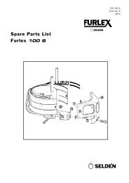
5121. Forestay/eye terminal2. Top guard3. Halyard swivel4. Snap shackle5. Luff extrusion6. Distance tube7. Joining sleeve8. Long joining sleeve9. Sail feeder10. Sail feeder connector11. Lower bearing assembly12. Tack ring13. Adjustment screw (fork)14. Line drum half15. Line guard housing16. Line guard17. Line guard bracket18. Line guide fitting19. Locking block20. Through-deck fitting21. Adapter tube and adapter22. Bush374610985211615122217142011184131419
6ASSEMBLY2 Checklist2.1 <strong>Furlex</strong> box:Forestay wire with top bearing.Eye terminal with toggleHalyard swivel with snap shackleLower bearing assembly with snap shackleThrough-deck fitting with screws andcutout template for deck hole.Adapter tube with adapter and luff sectionscrewsTwo line drum halvesLine guide fitting
7Line guard housingLocking blockFurling line2 halyard leads 508-128 with insulatorsheets incl. 6 screwsDrill bit Ø 5.3 mm (7/32")6 stanchion blocks 538-210-01PrefeederLocking adhesiveLubricating greaseTop guard incl. 4 screws<strong>Manual</strong>sSpare parts listCertificate of guarantee
82.2 Foil packOne 660mm (26") luff extrusion with longjoining sleeveOne 1700 mm (67") luff extrusion withdistance tube.2<strong>400</strong> mm (94 ½") luff extrusions withdistance tube+ joining sleeve (number dependent onlength ordered.)Sail feeder (sail feeder + sail feederconnector.)One short connecting plate for each 2<strong>400</strong>mm (94 ½")luff extrusionOne long connecting plate (for sail feeder)One locking pin for 660 mm (26") luffextrusion2.3 ToolsTools needed for assembly:Hacksaw2 adjustable spannersPair of pliers ("Polygrip")Adhesive tapeFileMarker pen (water-proof)Set of Torx keysSet of Allen keys (metric)Steel measuring tape (20 m) (67’)KnifeFor halyard leads:Heavy-duty Philips screwdriverDrillDrill bit Ø 5.3 mm (included in package)2.4 Tools needed for making the hole in the deck for the<strong>Furlex</strong>:Hole saw Ø 152 (6") or jig sawDrill bit Ø 9 (11/32")
93 ASSEMBLY PREPARATIONS3.1 Forestay attachment - guiding principleThe guiding principle is that the forestay connections should allow sufficient articulationin all directions. In most cases a toggle should be fitted between the <strong>Furlex</strong> stay andthe forestay attachments.3.2 Mast attachmentSome Seldén forestay attachment options are shown below, illustrating the rules and exceptions. ForH dimensions, see table 3.3.3.Fig. 3.2.a Fig. 3.2.bHFLFLForestay attachment on masthead rigs: alwaysconnect the stay with a toggle to give fullarticulation.Forestay attachment on fractional rigs, Seldéntype: connect to existing toggle.3.2.1 Dimensions of top eye terminal<strong>Furlex</strong> Series Wire Dim. TED 1) TET 2)TETTEDØ 12 20 (25/32") 15 (19/32")<strong>400</strong> <strong>TD</strong>Ø 14 23 (29/32") 17 (43/64")Fig. 3.2.e1) Terminal Eye Diameter2) Terminal Eye Thickness
103.2.2 Dimensions for toggles and extension links(toggles available from your <strong>Furlex</strong> dealer)Toggle typeForestay dimensionsØ 12 Ø 14Eye/fork toggle Article no. 174-125 174-125D1D2Length (H) 95 (3 ¾") 95 (3 ¾")Ø Eye (D1) 20 (25/32") 20 (25/32")HØ Clevis pin (D2) 19 (3/4") 19 (3/4")Fig. 3.3.eW2Fork width (W2) 22 (7/8") 22 (7/8")Fork/fork toggle Article no. 517-052-02 517-053-02D1HFig. 3.3.fW1D2W2Stemball / eye toggle withfork/fork toggleLength (H) 65 (2 9/16") 80 (3 5/32")Ø Riggnit (D1) 19 (3/4") 22 (7/8")Fork width (W1) 20.5 (13/16") 20.5 (13/16")Ø Clevis pin (D2) 19 (3/4") 22 (7/8")Fork width (W2) 21 (13/16") 23 (29/32")Article no. 517-069-01 -Length (H) 226 (8 7/8") -D1RØ Stemball (D1) 34 (1 11/32") -HBHD2Height (HB) 8.5 (11/32") -Radius (R) 15 (19/32") -Ø Clevis pin (D2) 19 (3/4") -Fig. 3.3.gW2Fork width (W2) 21 (13/16") -Eye/fork extension link Article no. 517-075-01 517-076W1D2Length (H) 190 (7 ½") 190 (7 ½")HD1W2Ø Clevis pin (D1) 19 (3/4") 22 (7/8")Fork width (W1) 20.5 (13/16") 20.5 (13/16")Ø Eye (D2) 20 (25/32") 22.5 (7/8")Fig. 3.3.hGauge (W2) 12 (15/32") 16 (5/8")
113.3 Hull attachmentThe lower bearing assembly of the <strong>Furlex</strong> <strong>TD</strong> system is to be regarded as an extension of the forestayfitting inside the hull. As it is locked horizontally at deck level, there is a toggle fitted between thelower bearing assembly and the forestay/luff section. This toggle, together with the universal jointfunction of the adapter tube, will create the required articulation as per the guiding principle item 3.1.Check that the through-deck fitting does not interfere with the pulpit, navigation lights, bow anchor orother deck fittings.Check that the anchor well drains freely.Make sure that the forestay fitting in the anchor well is designed and constructed to take the full forestayload.
123.4 Fitting below deck3.4.1 Lower bearing assemblyMake sure that there is enough space betweenthe forestay fitting and deck for thelower bearing assembly before the hole ismade. (See fig 3.4.a and table 3.4.2 for dimensionsof the lower bearing assembly.)Fig. 3.4.a3.4.2 Dimensions for installationAmmBmmCmmDmmEmmFmmGmm<strong>400</strong> <strong>TD</strong>440-630(17 1/3" ~24 13/16)210(8 17/64")255(10")22(7/8")19(3/4")26(1")193(7 19/64")The dimension F is nominal. In this area the thickness of the deck should not exceed 20 mm (25/32")If the deck is thicker than 20 mm, it should be possible to reduce this with a cavity. This will allowthe clearance for the top forward drum edge. If the deck is of sandwich construction, ensure that watercannot enter the core material and cause structural damage.<strong>Furlex</strong> <strong>TD</strong> incorporates an integral screw for fine adjustment of the under deck dimension "A", Thissimplifies adjustment between different boats. Extra extension links and toggles are available. (Fordimensions see table 3.2.2).For larger gaps: use a custom-made stainless steel bar or rod stay. Short wire pendants are not recommendedas the forestay load may not be distributed evenly and wire will not resist the torque whichmay be produced.Regarding "Routing of the furling line", see chapter 6.3 for further instructions.
133.5 Location of the through-deck holeThe bearing of the through-deck fitting has aspherical surface which compensates for smallerangle discrepancies between forestay andthrough-deck fitting. However, it is important tominimize the discrepancies to achieve maximumfurling performance. The angle between theforestay and deck must be between 72° and 74°.If the angle exceeds these limits, spacers mustbe added between the through-deck fitting andthe deck, so that the conditions are fulfilled. (Seefig. 3.5.a).73±1ºFig.3.5.a3.5.1 How to decide the intersection point of the forestay on the deckThe best method of determining the locationof the through-deck fitting is to stay the mastusing a forestay which extends though a smallerhole in the deck (See fig. 3.5.b). Two differentmethods for deciding the intersection point areshown below. For both methods, it is assumedthat the deck is of uniform thickness.Fig.3.5.b
143.5.2 Mast is not stepped 3.5.3 Mast is stepped using an existingforestay on deck (where <strong>Furlex</strong><strong>TD</strong> system is to be fitted in the samelocation)1.2.3.Establish the forestay angle (FA). Use anaccurate drawing, which shows details ofthe area of the deck where the <strong>Furlex</strong> will beattached, to be able to determine the preciseforestay angle (see fig 3.5.c).Transfer this angle to a cardboard jig.Press the jig against the underside of the deckand move it longitudinally until the edgerepresenting the forestay line intersects thehole in the forestay fitting in the anchor well.Mark the intersection point on the undersideof the deck and drill a 6.5 (1/4") mm holethrough the deck.Fig. 3.5.cFor further fitting work see chapter 4.1.1.2.3.4.5.6.7.8.Make a jig which represents the forestayangle (FA) above deck (See fig 3.5c)Using this jig, mark the angle CSA betweenthe forestay fitting in the anchor well and thedeck fitting intersection pointIf these angles are equal, the existing forestayfitting is correctly located.If the angles are not equal, the forestay angleFA must be used also below deck to decidethe intersection point.Press the jig against the underside of the deckand move it longitudinally until the edgerepresenting the forestay line intersects thehole in the forestay fitting in the anchor well.Mark the intersection point in the fore-and-aftdirection accurately.Remove the forestay. The recommendedprocedure is to first slacken the backstay.Then pull the masthead forward using thegenoa halyard. Secure the halyard using a"D" shackle or tie to a strong deck fitting. Forsafety reasons do not use the halyard snapshackle.NOTE. If the forestay is to be used to decidethe forestay length FLD (see fig. 3.7.a), thesetting of any rigging screw must not bechangedMeasure the height CH (see fig 3.7.a) on theforestay fitting and enter the figure in table3.6.1.Remove the forestay fitting from the deck.Mark the intersection point on the undersideof the deck by drawing a line along thelongitudinal centreline of the boat and usingearlier marking as per item 3.Drill a 6.5 mm hole at the intersection point.Always use a strong "D" shackle or tie the halyard!
153.6 Calculating the length of the forestay wire(The following is valid for a yacht with the mast stepped.)1. Determine the rake of the mast with the fore-/backstay tensioned.2. Slacken the backstay as much as possible, but make sure that any rigging screw is not unscrewedso far that the threads are no longer visible "on the inside". The forestay setting should not beadjusted. If the forestay rigging screw must be adjusted, first mark its thread with adhesive tape.3. Pull the masthead forward using the genoa halyard. Secure the halyard using a "D" shackle or tie itto a strong deck fitting. For safety reasons, do not use the halyard snap shackle.Always use a strong "D" shackle or tie the halyard!4. Take down the forestay. If the rigging screw was adjusted, return it to its original setting.5. Measure the forestay length (FL) with just enough tension to keep it straight.6. Enter the measurement in Table 1 below, under the heading "Your forestay", in the row marked FL.7. Calculate the new wire length WL in Table 1. Refer to the column marked "example" and fig. 3.7.ato see how this is done.3.6.1 Table 1: Calculation of forestay wire lengthFLCHFLDExisting forestay length FL including rigging screw, no tension.(See fig. 3.5.a)Add the distance between the hole in the chain plate and deck level.The measurement to be taken along the forestay line. (See fig. 3.5.c)FL + CH = FLD. = FL also corresponds to any measurement taken fromthe rig drawing of the boat.Yourforestay+ +Example(<strong>400</strong> <strong>TD</strong>/Ø12)21.50010021.600<strong>TD</strong>HDeduction for the level of <strong>Furlex</strong> <strong>TD</strong> above deck<strong>TD</strong>-deductionØ 12 mm wire: 250 mm (9 27/32")Ø 14 mm wire: 250 mm (9 27/32")NFL New forestay length =Deduction for wire terminal + toggle- -25021.350TWL<strong>TD</strong>-deductionØ 12 mm wire: 110 mm (4 1/3")Ø 14 mm wire: 135 mm (5 5/16")Cutting measurement. The new forestay wire is to be marked atthis point.- -= =11021.240240
163.7 Calculating the length of the luff extrusion1. Insert the length of the new forestay wire (WL) as calculated in "Table 1" into "Table 2", in the rowmarked WL under the heading "Your extrusion".2. Calculate the number of full length extrusions and the length of the top extrusion.3.7.1 Table 2: Calculation of luff extrusion lengthWL Length of new forestay wire (as per Table 1)YourextrusionExample(<strong>400</strong> <strong>TD</strong>/Ø12)21.242440A + BFixed deduction (A+B):C+DCA+B deductionØ 12 mm wire: -950 mm (37 13/32")Ø 14 mm wire: -940 mm (37")C+D=Max. number of 2<strong>400</strong> mm (94 ½") extrusions which together are shorterthan C+D: (............ex x 2<strong>400</strong> = C ) C=D Length of top extrusion =The top extrusion is normally cut from the 1700 mm (67") extrusion.Round the edges of the cut end using a file.- -95020.290(8 extrusions)19.2001.090If the top extrusion is shorter than 700 mm (27 9/16"), the jointwill be too near the top. In this case replace the uppermost fulllength2<strong>400</strong> mm extrusion with the 1700 mm (67") extrusion. Inthis way the joint is moved 700mm down the stay. Adjust the C andD measurements as follows:Deduct 700 mm (27 9/16")from the C measurement.Add 700 mm (27 9/16") to the D measurement.EE deductionØ 12 mm wire: -510 mm (20")Ø 14 mm wire: -560 mm (22")Deduction:Length of distance tube E=-=-=510580
ECB17A DFL = Existing forestay lengthFLDNFLWL T<strong>TD</strong>HFig. 3.7.aCH
184 Assembly of the <strong>Furlex</strong> system4.1 Making deck hole and fitting of through-deck fittingThe best way to decide the location of the through-deck fitting is to step the mast with a forestay,which passes through a smaller hole in the deck. If using this procedure follow the instructions belowstarting at item 1. If making the hole for the through-deck fitting is the first step, start at item 5.1. Using the 6.5mm (1/4") hole at the intersection point (see fig. 3.5.3) as its centre, cut a Ø 50 mm(2") hole in the deck.2.Fig. 4.1.aStep the mast and use a genoa halyard (the one intended for the<strong>Furlex</strong>) as forestay. Lead the halyard through the hole in the deckand attach it to the hole in the forestay fitting Attach the halyard witha D-shackle fitted to the halyard with a knot or talurit. If the halyardis fitted with a snap shackle this should not be used for safety reasons.NOTE! Always use a strong "D" shackle or tie the halyard!3.Fig. 4.1.bMark the position of the halyard on the edge of the 50mm (2")hole longitudinally as well as laterally.4. Take the tension off the genoa halyard, using another halyard. Disconnect the first genoa halyard.5.Fit a piece of plywood or similar, using 3 screws asper fig. 4.1.c. Locate the screws close to the hole edge toprovide clearance for the jigsaw/hole saw. Note: To make themarkings more precise, the 50 mm (2") hole in a deck of morethan 5 mm (3/16") should be filled with a piece of wood and"quick curing " filler.6.Fig. 4.1.cFig. 4.1.dPut the enclosed hole jig on top of the hole: Check that the jigreference lines coincide with the deck markings. Secure the jigwith adhesive tape.
216. Tighten the screw lightly.Fig. 4.3.f37.==Adjust the line guide vertically so that it ismidway between the line drum flanges. If thecasing or line guard come into contact with theline drum flanges, unnecessary friction will becaused.Fig. 4.3.g8.Adjust the alignment of the line guide towardsthe lead block and tighten the screw. (See alsochapter 6.3, "Furling line arrangement".)Fig. 4.3.hAt this stage the furling line arrangement should be fitted. See "Routing of the furling line",chapter 6.3 for instructions. After the line is fitted, the line guard should be carefully re-aligned and thelocking screw permanently tightened.
224.4 Assembly of the luff sectionAssembly should be carried out on a horizontal surface. Connect the luff extrusions one by one asfollows:1.Fig. 4.4.aThe long joining sleeve must be in the 660 mm (26") luff extrusion when commencing assembly.2.Fig. 4.4.bFit the long connecting plate at the same time as the sail feeder as shown in the diagram. Push thejoining sleeve up so that it is flush with the top edge of the sail feeder.3.Fig. 4.4.cRemove the 300 mm (11 ¾") joining sleeve from a 2<strong>400</strong> mm (94 ½") extrusion (this joining sleeveis to be used later for the top extrusion). Connect the 2<strong>400</strong> mm (94 ½") extrusion to the 660 mm(26") extrusion. Push the long joining sleeve of the 660 mm (26") extrusion into the 2<strong>400</strong> mm (94½") extrusion until it lies flush with the lower edge of the 660 mm (26") extrusion.4.Fig. 4.4.dPlace the collar of the adapter tube onto the extrusion. Insert the locking pin together with thelocking adhesive. Secure the pin with a piece of adhesive tape. (The tape is removed when theadapter tube/adapter is slid on.)Note: Do not allow locking adhesive to come into contact with the skin!
235.JFig. 4.4.eFit a joining sleeve into the next 2<strong>400</strong> mm (94 ½") extrusion together with a connecting plate.Connect this to the lower extrusions. Using a spare joining sleeve, push in the distance tube fromthe top until the lower joining sleeve touches the distance tube below the join. Check that thedistance (J) between the end of the distance tube and the end of the extrusion is approximately halfthe length of a joining sleeve.6.Fig. 4.4.fConnect the remaining extrusions according to "Table 2" (chapter 3.7.1).7.Fig. 4.4.gFit the halyard swivel over the top end of the extrusion, slide it down as far as the sail feeder andsecure it in this position with adhesive tape. Fit the top guard and secure it with the two pre-fittedscrews. Tighten the screws until they bottom, but do not over-tighten.8.Fig. 4.4.hSlide on the stainless steel adapter tube. Protect the tube exterior surface from scratches. Also becareful that the adapter tube does not scratch the luff section.
244.5 Fitting the wire1. Stretch the <strong>Furlex</strong> wire out by hand on a flat surface. Be careful when you open the wire coil as itmay uncoil quickly.NOTE! Be careful when you open the wire coil!2. Measure the wire from the centre of the hole in the terminal end fitting. Mark the measurementWL carefully on the wire using a marker pen. (The WL measurement was calculated in "Table 1",chapter 3.6.1.)3. The wire is annealed and tapered, making it easier to fit into the extrusion. Do not cut the wireyet.4. Feed the wire through the luff extrusions from the top until the eye of the end fitting stops againstthe top guard. Secure it in this position with adhesive tape. If the wire catches inside the extrusion,turn it counter-clockwise until it passes the obstruction.5. Put adhesive tape around the wire on both sides of the cutting mark to assist cutting. Check that themeasurement between the cutting mark and the bottom edge of the 660 mm (26") extrusion is asshown in the following table 4.5.1.4.5.1 Wire should protrude:<strong>400</strong> <strong>TD</strong>Ø 12 mm wire: approx 170 mm (6 3/4")Ø 14 mm wire: approx 145 mm (5 3/4")6. Cut the wire. Round the end of the wire using a file.7.Terminal part Former Wedge SocketFig. 4.5.aUnscrew the socket, wedge and former from the terminal part.8.Fig. 4.5.bThread the socket onto the wire.
259.2 mmFig. 4.5.cSlide the wedge over the core of the wire. The core of the wire should protrude approx. 2 mm(5/64") from the wedge.10.Space the outer strands of the wire evenly aroundthe wedge and bring down the socket so that thestrands are held in place. Hold an adjustable spannerbetween the extrusion and the socket. Tappingthe core of the wire, locate it firmly in the socket.Check that the core of the wire protrudes approx. 2mm (5/64") from the wedge. See fig. 4.2.c.Fig. 4.5.dNOTE! Check that no strand slipped into the slot of the wedge.11.Bend the outer strands inwards a little using a pair of pliers,or tap the strands with a small hammer. In the latter case,rest the socket’s thread on a soft surface (wood or similar) toprevent damage.12.Insert the former into the threaded hole of the terminal part.Lubricate the socket’s thread with a long bead of lockingadhesive. Screw the terminal part onto the socket and tightencarefully, forcing the wire further into the terminal.13.Unscrew and check that the outer strands areevenly distributed around the wedge. If somestrands are crossed, correct their positions.Fig. 4.5.eFig. 4.5.f.fFig. 4.5.gNOTE! Check that no strand has slipped into the slot of the wedge!14. If assembly is unsuccessful and needs to be repeated, refer to the relevant sections of chapter17, "Dismantling the <strong>Furlex</strong>".15.Apply another 2 or 3 drops of the locking adhesiveto the thread and screw the terminal together,tightening it firmly. The terminal is nowpermanently locked.Fig. 4.h.g
2616. Check length NFL of the stay is according to "Table 1" (chapter 3.6.1) & fig. 7.a.1779 mmMark the 660 mm (26") extrusion with apermanent marker as shown. This will assist finalalignment with adapter + adapter tube.18.Fig. 4.5.iThe luff section unit is now ready to fit to the boat.See "Rigging", chapter 16.
275 Halyard routingHalyard routing is one of the most important things to attend to for correct assembly.The angle between the halyard and the forestay must be 5–10°, see fig: 5.4.e. If this angle is less,the halyard may wrap around the luff section when the sail is being furled, possibly damaging thehalyard and the luff extrusion. Failure to observe what is happening in this situation may even resultin damage to the forestay wire.Incorrect halyard routing can promote "halyard wrap" which may cause severedamage to the forestay, and put the entire rig at risk. If the sail is furled with the aid ofa winch, take great care. It can be difficult to control the tension on the furling line.May lead toFig. 5.a Fig. 5.b5.1 Halyard leadsTo avoid halyard wrap, 2 halyard leads are included in the <strong>Furlex</strong> kit. These are easy to fit and aresuitable for all makes of mast.When sailing, movement occurs between the wire halyard and the halyard lead. To prevent halyardwear, the halyard lead is made of bronze. This is "softer" than a wire halyard, so the halyard lead willwear before the wire. Halyard leads should therefore be inspected once a year and any sharp edgessmoothed with a file. The halyard lead should be replaced when wear reaches 50%. The halyard leadsare not covered by the 5-year <strong>Furlex</strong> warranty.
285.2 Halyard sheave boxA sheave box can also be fitted to the mast to meet the5–10° requirement. The sheave box will not damagethe halyard, nor is it worn by the wire. Installation ismore complicated but the box will eliminate the needto replace the halyard leads in future.Newly manufactured Seldén masts on which <strong>Furlex</strong>is to be fitted are always fitted with a sheave box.Sheave box kits with assembly instructions areobtainable from all <strong>Furlex</strong> dealers.Fig. 5.2.a5.2.1 Wire halyardØ 7(9/32")Ø 8(5/16")Rope Halyard dimension Ø 14 (1/2") Ø 16 (5/8")Sheave box AL-90 Ø 130Article no. 505-012-10 505-038-01Sheave width 16 mm (5/8") 20 mm (25/32")Fig. 5.2.b5.3 Spinnaker halyardIf the boat is equipped with a spinnaker halyard, this must be kept clear of the <strong>Furlex</strong> system to avoidhalyard wrap. An effective solution is to lead the halyard around the upper shroud and then down aftthe spreaders.Stowing a spinnaker halyard parallel to the <strong>Furlex</strong> stay is not recommended!5.4 Fitting the halyard leadThe <strong>Furlex</strong> kit contains 2 halyard leads. If the mastis equipped with two genoa halyards they shouldeach run through a halyard lead. The halyard leadscan be fitted side by side or moved round the sideof the mast if there is a lack of spaceFig. 5.4.aEach lead is supplied with a self-adhesive insulator sheet. It is important to fit this between the leadand the mast. The lead, which is made of bronze, can otherwise cause corrosion damage on thealuminium mast surface.Figs. 5.4.c–5.4.e give the fitting measurements for Seldén masts. These measurements can also beused for other makes of mast, but the angle must be checked carefully. Too great an angle may resultin unnecessary wear to the halyard lead.
29For the halyard routing to work properly, the halyard swivel must be in the correctposition to achieve the required angle of 5–10°.If the sail does not have the required luff length, this needs to be adjusted. (See Sail,7.1.)0 - 5°10° Halyard angle. No lead is needed.10°Fig. 5.4.bFig. 5.4.cMastheadwith halyard leads.<strong>400</strong> <strong>TD</strong>: 300 mm (11 13/16")5–10°Fig. 5.4.dTriple combi (fractional rig) with halyard leads.<strong>400</strong> <strong>TD</strong>: 300 mm (11 13/16")5–10°Fig. 5.4.eFitting instruction:1. Measure the position of the leads. Mark theposition with the self-adhesive insulator sheets.2. Drill the holes with the enclosed Ø 5.3 mm (7/32")drill bit, using the fitting as a jig. It is easiest to drillthe holes before the <strong>Furlex</strong> stay is fitted.3. Fit the halyard leads "over" the respective halyardas the halyard shackles are too big to be fed throughthe eye.4. Lubricate the screws with grease and mount thehalyard leads. The screws are self-tapping M6screws which can be screwed directly into the Ø 5.3mm (7/32") hole. The grease makes fitting easierand prevents corrosion.Fig. 5.4.f
306 Furling line arrangement6.1 Functional descriptionAs the sail unfurls, the furling line is wound onto the line drum. It is centred on the line drum throughthe hole in the line guide fitting, which has a stainless steel bush to reduce friction and wear on theline. The furling line is distributed evenly on the line drum by the light pressure exerted on it by theflexible line guard, which has low friction aluminium edge protectors.6.2 Winding the line onto the drumTurning the luff extrusion by hand, wind approx. 40 turns of the furling line onto the line drum.If the sail’s ultraviolet (UV) protection is fitted on the starboard side, the furling line shall exit onthe port side of the line drum. Turn the luff extrusion clockwise.If the UV protection is fitted on the port side, turn the extrusion counter-clockwise. The line willthen exit on the starboard side.Secure the line in the tack snap shackle. Accidental unfurling is then prevented.Fig. 6.2.aTo prevent accidental unfurling the line can be secured as shown in fig. 6.2.a.
316.3 Routing the furling lineThe illustration below shows a model arrangement of the furling line routing inside an anchor well toachieve maximum furling performance. The turning block inside the anchor well and the sheave boxrequired to lead the line through the deck are not included in the <strong>Furlex</strong> package as these parts mustoften be individually adapted for each boat.The furling line must enter the line drum perpendicular tothe forestay. There must be at least 300 mm from the drumto the first turning point of the line to make the line furlevenly on the drumBlocks with large sheaves on roller bearings are recommendedto minimize friction losses. (Avoid leading the linethrough tubes incorporated in the deck as this increases therisk of friction on the furling line.)Strength requirement: to cope with the loads for which the<strong>Furlex</strong> system is designed, the turning block below deckand through-deck passage sheave house must have a safeworking load of not less than:Wire Ø12: 12 000 NWire Ø14: 18 000 NWhen the line is fitted the line guide is finally aligned andthe locking screw is permanently tightened.( See "Assemblyof line drum and line guide" chapter 4.3)Fig. 6.3.aFig. 6.3.b300 mmThe line should be led aft to the cockpit via the lead blocks included in the <strong>Furlex</strong> package. The leadblocks are mounted on stanchions and the pulpit. See fig: 6.4.a (next page) for installation instructions.The final turning block by the cockpit is not included in the<strong>Furlex</strong> kit.This needs to be matched individually to each boatdepending on the attachment points, the line arrangementchosen and possibly also the type of other blocks on theboat.We recommend a swivel block which is free to self-align.The maximum working load of the block should not be lessthan:Wire Ø 12: 17 000 N (3820Lbs)Wire Ø 14: 25 000 N (5620Lbs)Fig. 6.3.cIt must be possible to belay the furling line securely. A block with a Cam-cleat workswell when securing a reef, but is unreliable if the boat is left unattended.The line should then be secured on a normal cleat for safety reasons. We recommend asingle turning block in combination with a cleat.If the furling line is accidentally released, the sail may unfurl and flap unchecked instrong winds. It could be damaged irreparably!
326.4 <strong>400</strong> <strong>TD</strong>: Fitting the lead blocksThe <strong>Furlex</strong> kit contains 1 articulated block to befitted preferably on a Ø 25 mm (63/64") pulpit and4 fixed stanchion blocks for fitting on a Ø 25 mm(63/64") stanchion. The fixed blocks can also befitted on Ø 30 mm (1 3/16") stanchions, but thestandard screws must be replaced by M6-25 mmscrews.Assembly:The blocks are fitted on the stanchions as shownin fig. 6.5.a. The screw heads should be turned intowards the boat.Fig. 6.4.a
337 The Sail7.1 Adapting the sail to the <strong>Furlex</strong> systemTo fit the <strong>Furlex</strong> system, an existing sail may need to be modified. The maximum luff length iscalculated as shown in table 7.1.1 and fig: 7.1.b. FLD - (F+E) (existing forestay length FLD asper table 3.6.1 – less head and tack deduction).It is most important that the halyard swivel is located so that the halyard satisfiesthe 5–10° angle requirement. If the sail prevents the swivel from reaching the correctposition, the luff length needs to be adjusted.IF THE SAIL IS TOO LONG: Shorten the sail, e.g. in conjunction with changing to aluff tape compatible with <strong>Furlex</strong>.IF THE SAIL IS TOO SHORT: Lengthen the sail by means of a wire pendant fitted tothe head of the sail. Attach the pendant directly to the sail by a talurit splice to preventunintentional removal, loss or exchange. All the boat’s foresails should be adjustedto the correct luff length (see chapter 7.3). There must be a minimum distance of 80mm between the top of the halyard swivel and the top guard when the sail is fullytensioned. "Cutback" for tack see table 7.1.1.The luff tape must be compatible with the <strong>Furlex</strong> luff extrusion. See luff extrusion measurementsin table 7.1.1.If the sail is to be fitted with UV protection, this is best placed on the starboard side. The tack ofthe sail will then be in line with the luff grooves of the luff section when unrolled (see chapter 12,"Reefing"). If the sail already has UV protection on the port side, the tack will be turned slightlyto starboard. The free turn of the tack ring will function equally well.Use webbing loops at the sail head and tack instead of eyes (cringles). The sail will then formtightly round the luff extrusion when furling, and achieve a better shape when reefed.
FE347.1.1 Table of sail measurements<strong>Furlex</strong> type<strong>400</strong> <strong>TD</strong>Head deduction F 620 (24 7/16")Tack deduction E(any additional toggle or link must be added to E)210 (8 ¼")Cutback95 (3 ¾")Internal diameter of luff groove DLG Ø 8 (5/16")Width of luff groove WLG 3.0 (1/8")WLGDLGOverall extrusion dimensions 48.5x34 (1 29/23" x 1 11/32")Fig. 7.1.aMax sailspaceFLD -(F+E)FLD1100 mmCBFig. 7.1.b7.2 Sail shapeThe design of a sail can vary depending on its intended use and the desired performance.The clew of the sail can be high or low.In most cases a genoa has a low clew, with the foot sweeping as close to the deck as possible. Toachieve the optimal trim of a reefed sail you must be prepared to adjust the sheeting point.
35Smaller foresails such a cruising jib will have a higher clew, giving better visibility under the sail,easier passage over the guard rail and less exposure to waves breaking over the foredeck in heavyweather. This type of sail often requires less adjustment of the sheeting position when reefed (Seechapter 12, "Reefing").A furling genoa is usually a compromise between optimum performance and a more practical sail.The sail is designed for both light and strong winds, and is cut with less draft, giving it a flatter shapewhen reefed.Several methods have been developed to improve the shape of a reefed sail. Many sailmakers use"foam" as a filling material along the luff of the sail. The foam is tailored to match the sail cut, andincreases the diameter of the sail roll when reefing. A larger diameter of the sail roll gathers in moresailcloth per turn and the draft is reduced by varying amounts along the luff extrusion.Together with the "free turn" (See chapter 12, "Reefing") this can give the best reefed sail shape.7.3 Determining the length of the pendantTo hoist the sail see the description in chapter 11.1.1. Attach the head of the sail directly to the halyard swivel.2. Tack the sail at deck level with a piece of rope between the sail tack and the tack snap shackle onthe lower bearing assembly.3. Hoist the sail (See chapter 11.1, "To hoist the sail"). Adjust the rope length at the tack so that thehalyard swivel attains its top position, i.e. the 5–10° requirement is satisfied, when the halyard isfully tensioned.4. There should never be less than 80 mm (3 5/32") clearance between the top of the halyard swiveland the top guard when the sail is fully tensioned.5.6.min. 80 mmFig. 7.3.aMeasure the length of the rope while thehalyard is still tensioned.Fig. 7.3.bAttach a wire pendant corresponding to thelength of the rope directly to the head of thesail by a talurit splice. This cannot then beremoved unintentionally, lost or exchanged.7. All the boat’s foresails must be adjusted to the correct luff length.For the halyard routing to work properly, the halyard swivel must be in the correctposition to achieve the required angle of 5-10°.
36OPERATING MANUALTo derive the maximum benefit and enjoyment from your <strong>Furlex</strong> system, we recommend that youstudy this operating manual carefully.All safety-related information is indicated by the following symbol.This information must be followed to avoid damage to the system and the risk ofpersonal injury. The 5-year guarantee on the <strong>Furlex</strong> system is only valid if the systemis operated correctly according to the manual.Unless you are fitting the <strong>Furlex</strong> system yourself, you do not need to read the entire assembly manual.However, there are references in the operating manual to certain sections of the assembly manual. It isvery important to read and note these cross references.Any additional fittings recommended in the manual are obtainable from your nearest <strong>Furlex</strong> dealer.Seldén’s home page: www.seldenmast.com
3710 Halyard routing10.1 SummaryIMPORTANT POINTS!Routing the halyard is one of the most important aspects of system assembly for safe, trouble¬freesailing using the jib furling and reefing system.The angle between the halyard and the forestay must be 5–10°. See fig: 5.4.b. If the angle isless, the halyard may wrap around the luff section when the sail is being furled, possibly damagingthe halyard and the luff extrusion. Failure to observe what is happening in this situation mayeven result in damage to the forestay wire."Halyard wrap" may cause severe damage to the forestay and put the entire rig at risk. If the sailis furled with the aid of a winch, take great care. It can be difficult to control the tension in thefurling line.If the 5–10° requirement is not satisfied, halyard leads or a sheave box must be fitted to avoidhalyard wrap.2 halyard leads are enclosed in the <strong>Furlex</strong> kit. Check if these are fitted.See also under "Halyard routing", chapter 5.May lead toFig. 10.1.aFig. 10.1.bWhen sailing, movement occurs between the wire halyard and the halyard lead.To prevent halyard wear, the halyard lead is made of bronze. This is a softer materialthan a wire halyard, so the halyard lead will wear before the wire.Halyard leads should be inspected once a year and any sharp edges smoothed with afile. The halyard lead should be replaced when wear reaches 50%.The halyard leads are not covered by the 5-year <strong>Furlex</strong> warranty.
3810.2 Halyard sheave boxA sheave box can also be fitted to the mast to meet the 5–10° requirement. The sheave box will notdamage the halyard, nor is it worn by the wire. Installation is more complicated but the box willeliminate the need to replace the halyard leads in future as above.Newly manufactured Seldén masts on which <strong>Furlex</strong> is to be fitted are always fitted with a sheave box.Sheave box kits (with assembly instructions) are obtainable from all <strong>Furlex</strong> dealers.See table 5.2.1 and fig: 5.2.a for further information.10.3 Spinnaker halyardIf the boat is equipped with a spinnaker halyard, this must be kept clear of the <strong>Furlex</strong> system to avoidhalyard wrap. An effective solution is to lead the halyard around the upper shroud and then aft of thespreaders.Stowing a spinnaker halyard parallel to the <strong>Furlex</strong> stay is not recommended!
3911 Sailing with <strong>Furlex</strong>11.1 To hoist the sailThe forestay must be properly tensioned each time the sail is hoisted. You shouldtherefore tension the backstay and any running backstays before hoisting the sail.1. Tension the forestay for hard close-reach sailing before the sail is hoisted. If the sail is hoisted andfirmly tensioned before the forestay, this may put excess strain on the halyard, halyard swivel andsail when the forestay is tensioned afterwards.2. Lay out the sail on deck. It should be carefully flaked down with the tack turned forward.3. Turn the tack ring counter-clockwise if the furling line exits on the port side of the drum, orclockwise if it exits on the starboard side.Fig. 11.1.a4. Attach the tack of the sail to the tack snap shackle.5. Tie the line of the prefeeder to the hole below the tack snap shackle or to the shackle itself.6. Tie the sheets to clew. Feed the sheets through the sheet blocks and on to the cockpit. Make afigure of eight knot at each end.7. Attach the halyard to the upper eye of the halyard swivel.
408. Feed the luff tape through the sail feeder into the luff groove. If the furling line exits on theport side of the line drum, the sail should be hoisted in the starboard groove. If the line exits onthe starboard side, use the port groove. Hoisting the sail in the "right" groove reduces initialresistance when furling the sail, which then has less of a "fold" along the forestay than if theother groove is used.9. Hoist the sail. The pre-feeder assists luff tape feed by steering the sail in towards the luffextrusion and sail feeder at a small angle. Tension the halyard until a vertical crease appears inthe luff of the sail, then slacken off until the crease disappears. Belay the halyard.10. Remove the prefeeder from the tack ring.11. Furl the sail on the <strong>Furlex</strong> luff section by pulling on the furling line. Let the windward sheet runfreely. Keep some tension in the leeward sheet, for example by placing a turn around a winch.It is important to furl the sail tightly and evenly, as a sail which is furled too loosely may blowout a little in strong winds. If the boat is left unattended, the sail may flap until it tears. A veryloosely furled sail may also cause unnecessary wear, as the sail roll will swing back and forth inthe wind.12. Check the number of turns of the furling line remaining on the line drum. When the largest sail isfurled tightly, there should be 3–5 turns left. To adjust the number of turns, detach the sheet andturn the <strong>Furlex</strong> luff extrusion by hand until the correct number of turns is on the drum. Whenfurling in strong winds, the sail will roll more tightly, requiring more turns on the line drum andmeaning that more line will be needed. Make sure you always have sufficient turns of line on thedrum.13. Check that the halyard swivel is at least 80 mm (3 5/32") from the top guard and that thehalyard angle satisfies the 5–10° requirement.14. Once all these points have been checked, mark the halyard as shown inthe diagram to prevent overtensioning by a winch or when the forestay/backstay is adjusted. Mark the maximum tension position of the backstayadjuster.Fig. 11.1.b15. The forestay tension can now be adjusted without putting too much strain on the halyard.Warning! Never tension the halyard when the sail is reefed or furled.11.2 Unfurling the sail(Partial unfurling: See chapter 12, "Reefing")1. Release the furling line and the windward genoa sheet. Allow these to run freely while the sail isbeing unfurled.2. For a controlled unfurling manoeuvre, it is best to place a turn of the furling line around a winchor a half-turn around a cleat. This introduces some drag, which is particularly useful in strongerwinds.3. Place a turn of the leeward genoa sheet around a winch and unfurl the sail by pulling in the sheet.Once the wind catches the sail it will unfurl more easily. The best point of sail for unfurling isbetween close reach and beam reach, as the wind will then fill the sail quickly.4. Place a few more turns of the sheet around the winch and sheet the sail in to the desired trim.
4111.3 Furling the sail1. Release the windward sheet and ensure that it can run freely.2. Furl the sail by pulling the furling line. Release the leeward sheet but keep a little tension on it, forexample by placing a turn around a winch. It is important to furl the sail tightly and evenly, as asail which is furled too loosely can blow out a little in strong winds. If the boat is left unattended,the sail may flap until it tears. A very loosely furled sail may also cause unnecessary wear, as thesail roll will swing back and forth in the wind.3. Belay the furling line carefully. If the boat is left unattended, the furling line should be belayed ona cleat for safety.If the furling line is accidentally released, the sail may unfurl and flap unchecked instrong winds. If left for any length of time, it could be damaged irreparably!If the boat is left for a relatively long period, it is a good idea to take down the sail and stow it belowdeck. It is then protected from UV radiation and dirt. Alternatively, a sail cover ("furling tube") can beused to protect the sail.
4212 ReefingThe size of the working sail area is infinitely variable with a jib furling and reefing system. Even if thesail is designed as a furling sail incorporating foam etc. and the <strong>Furlex</strong> system is equipped with a "freeturn" (see below), a reefed sail can never achieve the same efficiency as an unreefed sail of equal size.If the boat is equipped with more than one furling sail, these can be changed to suit the different windconditions.12.1 Free turn<strong>Furlex</strong> is equipped with a tack swivel, meaning that furling of the tack is delayed by one revolutionin relation to the luff extrusion. This causes the sail to be flattened out a little before the tack and thefoot are furled. Since the tack is reinforced by several layers of sail cloth, this will increase the sailroll more with each revolution than the rest of the luff , thereby impairing the shape of the reefed sail.<strong>Furlex</strong> compensates for this by means of the tack ring delay.We refer to this function as the "Free turn".12.2 Reefing under sailIn strong winds it may be necessary to reef the sail. It is important then to furl the sail tightly, asthis both preserves the sail and gives it a better shape.The best point of sail for reefing is on a close reach to beam reach. The wind will then partly fillthe sail and help to improve its shape when reefed.If using a winch for the furling line, first check that there is no obstruction which may interruptthe furling operation and possibly cause damage.1. Slacken off the leeward sheet until the sail just begins to flap along the luff.2. Pull in the furling line so that the sail is furled and flattened out. Belay the furling line.3. Repeat the procedure as required to obtain the desired sail area.If using a winch for the furling line, first check that there is no obstruction which mayinterrupt the furling operation and possibly cause damage.12.3 Setting a reefed sail from the furled positionYou will achieve the best sail shape by first unfurling the sail completely and then reefing downto the appropriate size. Pull in the furling line and keep the sheet well tensioned. The sail will thenform a tight roll and its shape will be improved.If the wind is too strong, or there are other reasons for not wanting to unfurl the sail completely,it can be reefed from the furled position. The sail should then be furled relatively tightly. Thesail cannot be expected to have as good a shape when using this method. Wear on the sail is alsoincreased.
4312.4 Adjusting the sheeting positionWhen the sail is reefed, it may be necessary to adjust the sheeting position. For a sail with a low clew,the sheeting position has to be adjusted even when the sail is slightly reefed, a sail with a high clewrequires less adjustment. See fig. 12.4.a. As a rule, however, you must be prepared to adjust thesheeting position as necessary to give the best sail trim.Sail with a low clewSail with a high clewFig. 12.4.aThe angular variation of the sheet relative to the deck is less for a high-clewed sail. The comparison isbased on the same number of furling revolutions.Adjustment of the sheeting position is made considerably easier if a floating sheet point arrangementis used.. The traveller position is adjusted along the track by means of a line running through ablock in the front of the track. The line is best routed to the cockpit where it is secured. The travellerposition can also be adjusted under load with the aid of a winch.Fig. 12.4.bMany furling foresails have markings in the foot for different reefing positions. After you have testedcombinations of sail area and sheeting position to see which function satisfactorily, you can use thesemarkings as a reference and mark suitable sheet points on the track.
4413 <strong>Furlex</strong> for racingMany racing yachtsmen have exploited the advantages of the jib furling and reefing system with greatsuccess. The sail can be partly furled before the start, giving good visibility and easy manoeuvringof the boat. Just before starting, the sail is unfurled and the boat crosses the line under full sail. If theboat has a small crew, the advantages are obvious.The <strong>Furlex</strong> system can be reconfigured from a furling system to a twin-groove racing headfoil ifthe halyard swivel is lowered below the sail feeder. To remove the sail feeder see chapter 17.2,"Dismantling". Lower the halyard swivel and refit the sail feeder. The twin grooves now makes swiftsail changes possible.Fig. 13.4.a.
4514 Adjusting the forestay length<strong>Furlex</strong> <strong>400</strong> <strong>TD</strong> is only supplied without a rigging screw.14.1 To lengthen the forestayThe forestay can be lengthened by fitting extra toggles, see table 3.3.3. Several toggles are usuallyrequired to change the mast rake noticeably. These can only be fitted at the upper end of the system.On a <strong>Furlex</strong> with an Ø12 mm forestay of the normal length (20000 mm), the masthead is moved 220mm aft if the forestay is lengthened using a standard toggle (H=65mm).14.2 To shorten the forestayTo shorten the <strong>Furlex</strong> system the forestay wire as well as the luff section have to be shortened. See"Dismantling", chapter 17 and "Assembly of the <strong>Furlex</strong> system", chapter 4.NB: The system must never be shortened by removing the lower <strong>Furlex</strong> toggle betweenthe forestay and the lower bearing assembly. (See "Forestay attachment-guidingprinciple", chapter 3.1 and "Hull attachment", chapter 3.3)
4615 Maintenance of the <strong>Furlex</strong> systemTo ensure that the system rotates easily and functions reliably year after year, regular maintenanceshould be carried out. This should be done once a year, or perhaps when the boat is unrigged at theend of each season. Maintenance is simple, even when the <strong>Furlex</strong> is rigged on the boat. Halyard leadsshould be inspected once a year and any sharp edges smoothed with a file. The halyard leads shouldbe replaced when wear reaches 50%15.1 Lubricating the lower bearing assemblyFirst remove the line guide and the drum halves (seechapter 17). For best results, rinse the system withfresh water and let it dry. Lubricate all ball bearingsas described below using the grease enclosed with the<strong>Furlex</strong> kit. Lubricating holes Aand Care for the mostimportant bearings to be greased, as the <strong>Furlex</strong> system Drotates around these. Lubricating holes Band Darefor tack ring bearings. Unscrew theadjustment screw at the bottom of the lowerbearing part approx 20mm. If the stroke doesnot permit this, the stay must be disconnectedfrom the boat.Note. Secure the mast with a halyard beforethe stay is disconnected (see chapter3.5.3). The bearings of the through-deckfitting Eand Fhave Torlon® balls and donot need lubrication. However, they should be rinsedwith fresh water.BAFig. 15.1.aTools: 1 set of Torx keys1 set of Allen keys (metric)1 adjustable spanner1 pair of long-nosed pliers if the stay has to be disconnectedA, Band CPress grease into the holes A , Band C.FHEGDUnscrew the adjustment screw or disconnect the forestay as per instructions above. Press grease intothe hole D .Reset the adjustment screw to its original position. There should be a gap between the lower edge ofthe tack ring and the through-deck fitting of 4-5mm (3/16") when forestay is tensioned. Refit the lineguide and drum halves.15.2 Lubricating the halyard swivel1. Lower the halyard swivel down to the sail feeder.2. Press grease into the upper bearing through the recess Gand into the lower bearing throughopening Hin the plastic cover.
4715.3 Cleaning the <strong>Furlex</strong>Wash and rinse the entire <strong>Furlex</strong> system with fresh water and a mild detergent to remove dirt and saltcrystals.Note! Some detergents contain substances which can cause aluminium to corrode, so it is important torinse all detergent off thoroughly.When the parts have dried, the anodized surfaces of the luff extrusions can be treated with a siliconfreeboat polish or wax. This offers good protection and prevents particles of dirt from adhering andthen soiling the sail. The stainless steel components can be treated with a suitable polish.15.4 StorageThe <strong>Furlex</strong> system is preferably stored with the mast during the winter.Never wrap a damp or unwashed <strong>Furlex</strong> in plastic or other impervious material.In areas where frost can occur, the <strong>Furlex</strong> should be stored in a dry place or with its centre sectionsraised. This is to avoid ice damage to luff sections in sub-zero temperatures.Fig. 15.4.aFig. 15.4.bThe lower bearing assembly can be left in the boat during winter storage. In this case ensure that theanchor well is dry and well ventilated.The lower bearing assembly can equally well be dismantled and removed from the boat for storage ina clean and dry location. To remove the line guide and line drum see "Dismantling", chapter 17.3 &17.4. Once disconnected from the forestay fitting, the lower bearing assembly can be lifted out of thethrough-deck fitting.
4816 RiggingThe <strong>Furlex</strong> system is best transported and rigged together with the mast.16.1 Fitting the <strong>Furlex</strong> on a stepped mast1. Slacken the backstay as much as possible, but make sure that any rigging screw is not unscrewedso far that the threads are no longer visible "on the inside".2. Pull the masthead forward using the genoa halyard. Secure the halyard using a "D" shackle or tie itto a strong deck fitting. Do not use the halyard snap shackle for safety reasons.Always use a strong "D" shackle or tie the halyard.3. Tie a strong, flexible line around the luffextrusion. Make two clove hitches, the upperapprox.1 m from the top, taping over the knots sothat they cannot slide.4. Hoist the stay using a spare halyard.5. "Go aloft" and attach the top end of the <strong>Furlex</strong>system to the forestay attachment. Always use aproper bosun’s chair. If there are no free headsailhalyards use the main halyard. For furtherinformation, see "Working aloft" in Seldén MastAB’s "Hints and Advice" or contact your <strong>Furlex</strong>dealer.Fig.16.1.a6. Attach the stay to the headbox and then to the lower bearing assembly. Thesplit pin for the clevis pin should be opened by ~ 20°. It will then retain itsshape on dismantling, enabling it to be used again.Fig.16.1.b7. Lower the adapter tube and fit it to the cardan ringof the lower bearing assembly. Fit the bushes acc. tofig. 16.1c. Tighten the screws firmly. Tighten thelocking screws . Use locking adhesive.8. Adjust the luff extrusion so that the marking (see page26) is at the same level as the adapter at A . Tightenthe extrusion screws firmly.9. Tension the forestay to 20% of the wire’s breakingload. As the tension on the forestay cannot bemeasured easily when it is encased in the luffextrusion, this can be done using the backstay. Owingto the difference in the angle of these stays relativeto the mast, this is equivalent to approx. 15% of thebackstay’s breaking load on a masthead rig, assumingthat it is the same diameter as the forestay. (Forestaytension = approx. 1.25 x backstay tension.)A firmly tensioned stay offers the least furling resistance.12AFig.16.1.c3For further information, see Seldén Mast AB’s "Hints and Advice" or contact your <strong>Furlex</strong> dealer.
4916.2 Stepping the mast with <strong>Furlex</strong> fitted1.2.3.4.5.Lay the mast with the front uppermost.Connect the top end of the <strong>Furlex</strong> system to the forestay attachment.Lift the mast with the <strong>Furlex</strong> system lying on the leading edge ofthe mast.Have one person watching the <strong>Furlex</strong> system to ensurethat it does not get caught when lifting the mast.Keep the end of the stay outside the deck area in order to avoiddamage.Attach the stay to the boat as described in chapter 16.1 section6–8.17 DismantlingFig. 16.2.aNOTE! Do not dismantle the halyard swivel or lower bearing assembly.You will find it difficult to re-assemble them correctly(the ball-bearings are loose and difficult to refit!).Contact your <strong>Furlex</strong> dealer if service is required.17.1 Halyard swivelThe halyard swivel can be removed from the system by removing the top guard and sliding it over theend of the forestay wire. The stay also has to be detached from the mast.Alternatively, it can also be pulled downwards in conjunction with dismantling the sail feeder andremoving the lower bearing assembly.17.2 Sail feederRemoving the sail feeder:1. 2. 3.Fig. 17.2.bFig. 17.2 aSecure the stainless steel sail feederwith adhesive tape to prevent it fromfalling overboard during disassembly.Insert two small screwdrivers into thesmall slots as per the diagram. Forcethe screwdrivers apart so that the sidesof the sailfeeder connector are pressedout and its concealed clips are released.Fig. 17.2.cContinue the movement of the screwdriversand the sail feeder is "lifted out"of its seat.
150Reinstalling the sail feeder:4. 5.Fig. 17.2.dFig. 17.2.ePress on the sail feeder connector from the front of the luffextrusion.Clip the sailfeeder into th connector’s top recess, then pressthe sail feeder’s lower edge until it snaps into place.17.3 Line guide1. Unwind all the line from the line drum. Note the number of turns of line (for reassembly).2. 3.232Fig. 17.3.bFig. 17.3.aLoosen screws and slacken screw off afew turns.Lower the line guide fitting and remove it.4. Remove the line guard housing from the line drum.
5117.4 Line drum1. Dismantle the line drum halves by loosening the 2 screws.Fig. 17.4.a
5217.5 Wire terminal1.2.3.4.5.6.7.8.9.Remove the terminal part from the socket. See fig. 17.5.b and fig. 4.5.a.Remove the former at the bottom of the terminal part thread.Replace the terminal part, then loosen it ~2 turns.Tap the terminal part so that the socket is pushed up the wire. If necessary, secure the wire in avice. There should be at least 10 mm (25/64") of free wire between the top of the socket and thejaws of the vice.Unscrew the terminal part again.Cut all wire strands protruding outside the wedge at the bend (5 mm in on wire) (3/16"). See fig.17.6.a.Prise the wedge apart slightly by inserting a smallscrewdriver into the slot and turning. Tap on thescrewdriver so that the wedge slides off the wire.Twist the wire strands into the correct positionsaround the core (counter-clockwise when seenfrom underneath) and remove the socket.The wire can now be pulled out of the luff extrusion.Prior to reassembly of the forestay:Check that the shape of the wedge was not damaged on dismantling. If so, replace it.Cut the wire core flush with the outer strands. Remove any burrs with a file.Fig. 17.6.aNOTE! If the luff extrusions are to be disassembled prior to e.g. replacing a luff extrusion– do not pull out the wire. Go to chapter 17.6.The decrease in forestay length which results has very little effect on the mast rake. A decrease of 5mm in forestay length causes the masthead to move forward 35 mm (1 1/3") on a 20000 mm (65 ½’ )forestay.The decrease in length can also be compensated for by an increase in stay tension of 5% of the wire’sbreaking load compared with before. (However, permanent tension must not exceed 20% of thebreaking load of the wire.) If this reduction in wire length is unacceptable, the total decrease can bemade equal to a toggle length. The reduced measurement is compensated for by fitting an eye/forktoggle (see table 3.3.2).The luff extrusion and possibly the sail also should be shortened accordingly.17.6 Luff extrusion systemFor a better understanding of the following instructions, we recommend that you first read the sectionon assembly in chapter 4.1.1. Make sure that the luff extrusions are straight and placed on a flat surface.2. Slide the wedge over the core of the wire again.3. Push out the locking pin at the lower end of the 660 mm (26") luff extrusion.4. Hold the luff extrusion firmly and pull the wire’s eye terminal. This will bring the forestay, joiningsleeves and distance tubes out together, enabling the extrusions to be separated.If due to contamination or damage this method fails, the connection parts protruding can bedrilled out. Use a Ø 8 mm (1/3") drill bit.
55Problem Probable cause Action18.3 "The system ‘wobbles’ whenfurling and unfurling"18.4 "The sail unfurls after reefingor furling"• The forestay is too loose.• The sail is not furled tightly enough.• The furling line is not belayed.18.5 "The sail is hard to hoist" • The luff tape is too thick.• The sail is caught on something or isnot sufficiently loose on the foredeck.• Fault in halyard routing.• Dirt and salt in the luff groove.18.6 "The luff cannot be tensioned" • The halyard swivel comes into contactwith the top guard.• The angle between the forestay andthe halyard is too great.18.7 "The sail cannot be takendown"18.8 "The sail’s UV protection is onthe inside of the furled sail"18.9 "The sail is wrinkled at thetack"18.10 "The leach flogs despitesheeting hard"18.11 "The leach closes (bendsinwards)"• The halyard is wrapped around the topof the luff extrusion.• The halyard wraps around the luffextrusion as the sail is coming down.• The halyard is stuck.• The furling line is wound on the drumin the wrong direction.• The tack ring was twisted in thewrong direction before tacking thesail.• The sail is old or incorrectly cut.• Incorrect sheeting point.• Incorrectly tensioned leach line.• The sail is old or incorrectly cut.• Incorrect sheeting point.• The sail is old or incorrectly cut.• Tension the forestay.• Furl with some drag on the line.• Furl and belay the furling line.• Return the sail to the sailmaker andrefer to <strong>Furlex</strong> manual, chapter 7.1.1"Table of sail measurements".• Arrange the sail better on theforedeck.• Check the sheaves, winch etc.• Clean the luff groove.• The luff of the sail is too long. Havethe sail shortened by the sailmaker.• Shorten the sail or move the halyardlead up.• Ease the halyard off and try to reversethe system. Refer to the Assemblyand Operating <strong>Manual</strong>, chapter 5 &10 "Halyard routing".• Tension the halyard manuallykeeping a slight drag on it whiletaking the sail down.• Check the halyard routing (sheaves,stoppers etc)• Remove the sheet from the sail andgather the sail around the <strong>Furlex</strong>system with a rope. Pull on the lineuntil the drum is empty. Wind acouple of turns on the drum by handin the right direction. Unfurl the sail.Furl again, checking the number ofturns of furling line on the drum.• Unfurl the sail and ease off thehalyard. Undo the tack snap shackle.Rotate the tack ring "around thesystem" and retack the sail. Furlslowly and check that the furling ofthe tack is retarded by one revolutionin relation to the luff extrusion.• Consult your sailmaker.• Move the sheeting point forward.• Adjust the leach line (Consult yoursailmaker).• Consult your sailmaker.• Move the sheeting point backwards.• Consult your sailmaker.
5619 ChecklistGo through the checklist below and make sure that all the important instructions have been carriedout. This will ensure that the <strong>Furlex</strong> system functions safely and reliably under all conditions.19.1 Points to check before sailingSeechapterCheck that the angle between the halyard and forestay is 5–10° when thesail is hoisted.Check that the clearance between the halyard swivel and the top guard isnot less than 50 mm.Do all the sails used have the maximum luff length or an extension pendant?Check that no halyard can get caught in the halyard swivel or wrappedaround the luff extrusion.Check that the line guide eye does not deflect the furling line too much,as this can cause extra friction and wear.Check that the free turn is functioning, i.e. the tack swivel is turned in theright direction. A certain load on the sheet should cause the luff section torotate one revolution before the tack rotates.Check that the tack ring does not touch the through-deck fitting and causeextra friction.Check that the line guide fitting does not contact the line drum and flanges.Check that the <strong>Furlex</strong> stay articulates freely at the upper and lower attachment.Check that all the split pins are secured.57.17.15.36.312.14.24.33.13.3We are sure that your <strong>Furlex</strong> will give youmany years of enjoyment and wish youand your crew happy sailing.www.seldenmast.com595-240-E Printed in SwedenSweden: Seldén Mast AB, Tel +46 (0)31 69 69 00, e-mail info@seldenmast.com UK: Seldén Mast Ltd., Tel +44 (0)1329 50 40 00,e-mail info@seldenmast.co.uk USA: Seldén Mast Inc., Tel +1 843-760-6278, e-mail info@seldenus.com Denmark: Seldén Mast A/S,Tel +45 39 18 44 00, e-mail info@seldenmast.dk the Nether lands: Seldén Mid Europe B.V., Tel +31 (0)111- 698 120, e-mail info@seldenmast.nlFrance: Seldén Mast SAS, Tel 33 (0) 251 362 110, e-mail info@seldenmast.fr