MLR-352 MLR-352HSeries - Panasonic Biomedical
MLR-352 MLR-352HSeries - Panasonic Biomedical
MLR-352 MLR-352HSeries - Panasonic Biomedical
- No tags were found...

Create successful ePaper yourself
Turn your PDF publications into a flip-book with our unique Google optimized e-Paper software.
Operating InstructionsVersatile Environmental Test Chamber<strong>MLR</strong>-<strong>352</strong><strong>MLR</strong>-<strong>352</strong>H<strong>MLR</strong>-<strong>352</strong><strong>MLR</strong>-<strong>352</strong>H SeriesPlease read these instructions carefully before using this product, and save this operating instructionsfor future use.See page 63 for all model numbers.
CONTENTSINTRODUCTION P. 3PRECAUTIONS FOR SAFE OPERATION P. 4ENVIRONMENTAL CONDITIONS P. 7CHAMBER COMPONENTS P. 8Switch box P. 11Control panel P. 12Remote record terminal P. 13Remote alarm terminal P. 14INSTALLATION SITE P. 15Caution for installation environment P. 16INSTALLATION P. 17BEFORE COMMENCING OPERATIONInstalling inner attachments P. 19PREVENTING CONTAMINATION P. 20TOP SCREEN P. 21FUNCTIONS THROUGH CONTROL PANEL P. 22STANBY OPERATION (MENU/Std-by) P. 23SETTING OF KEY LOCK (MENU/Std-by)Setting of Key Lock (Key Lock) P. 24Setting of Key Unlock (Key Unlock) P. 25HIGH LIMIT/LOW LIMIT ALARM (MENU/Std-by) P. 26PROGRAMMING (MENU/Edit) P. 27EDIT OF SAVED PROGRAM (MENU/Edit) P. 33START OF PROGRAM (MENU/Run) P. 34JOIN FUNCTION P. 36SKIP OF STEP (MENU/Skip) P. 37STOP OF PROGRAM (MENU/Stop) P. 38AUTOMATIC DEFROST (MENU/Tools/Date Time) P. 39MANUAL DEFROST (MENU/M.def) P. 40VARIOUS SETTING (MENU/Tools) P. 41Display of log (Tools/Log) P. 41Setting of date, time, log (Tools/Date Time) P. 43Alarm setting (Tools/Alarm Setting) P. 44Key lock password setting (Tools/Key Lock PW Setting) P. 45Default setting (Tools/Default Setting) P. 46Delete of program (Tools/Delete User Data) P. 47LIGHT STEP (ILLUMINANCE SETTING) P. 49HUMIDITY CONTROL (<strong>MLR</strong>-<strong>352</strong>H ONLY) P. 501
CONTENTSROUTINE MAINTENANCE P. 51Cleaning of unit P. 51Replacement of fluorescent lamp P. 51Cleaning of evaporating tray P. 52Cleaning of filter P. 52ALARMS & SAFETY FUNCTIONSAutomatic set temperature alarm P. 53Automatic set humidity alarm (<strong>MLR</strong>-<strong>352</strong>H only) P. 53Safety functions P. 53Operation after power failure P. 53TROUBLESHOOTING P. 56DISPOSAL OF UNIT P. 57PERFORMANCE DATA (<strong>MLR</strong>-<strong>352</strong>H) P. 62SPECIFICATIONS P. 63PERFORMANCE P. 64SAFETY CHECKSHEET P. 652
INTRODUCTION■ Read this operating instructions carefully before using the Product and follow the instructions for safetyoperation.■ Our company disavows any responsibility for safety if the Product is used for other than the intendeduse or used with any procedures other than those given in this operating instructions.■ Keep this operating instructions in a suitable place so that it can be referred to as necessary.■ The contents of this operating instructions are subject to change without notice for improvement ofperformance or functions.■ Contact our sales representative or agent if any page of the operating instructions is lost or the pageorder is incorrect.■ Contact our sales representative or agent if any point in this operating instructions is unclear or if thereare any inaccuracies.■ No part of this operating instructions may be reproduced in any form without the expressed writtenpermission of our company.CAUTIONOur company guarantees the product under certain warranty conditions. Our company in noway shall be responsible for any loss of content or damage of content.Microsoft, Windows, Windows 7, Windows Vista, Windows XP and Windows 2000 are registeredtrademarks in the United States of Microsoft Corporation and various other countries.3
PRECAUTIONS FOR SAFE OPERATIONIt is imperative that the user complies with this operating instructionsas it contains important safety advice.Items and procedures are described so that you can use this unit correctly and safely.If the precautions advised are followed, this will prevent possible injury to the user andany other person.Precautions are illustrated in the following way:WARNINGFailure to observe WARNING signs could result in a hazard to personnelpossibly resulting in serious injury or death.CAUTIONFailure to observe CAUTION signs could result in injury to personnel anddamage to the unit and associated property.Symbol shows;this symbol means caution.this symbol means an action is prohibited.this symbol means an instruction must be followed.Be sure to keep this operating instructions in a place accessible to users of this unit.< Label on the unit >This mark is labeled on the cover in which the electrical components of high voltageare enclosed to prevent the electric shock.The cover should be removed by a qualified engineer or a service personnel only.4
PRECAUTIONS FOR SAFE OPERATIONWARNINGEnsure you do not inhale or consume medication or aerosols from around the unit at the time ofmaintenance. These may be harmful to your health.Never splash water directly onto the unit as this may cause electric shock or short circuit.Never put containers with liquid on the unit as this may cause electric shock or short circuit whenthe liquid is spilled.Never bind, process, or step on the power supply cord, or never damage or break the powersupply plug. A broken supply cord or plug may cause fire or electric shock.Do not use the supply cord if its plug is loose. Such supply cord may cause fire or electric shock.Never disassemble, repair, or modify the unit yourself. Any such work carried out by anunauthorized person may result in fire, or electric shock or injury due to a malfunction.Disconnect the power supply plug if there is something wrong with the unit. Continuedabnormal operation may cause electric shock or fire.When removing the plug from the power supply outlet, grip the power supply plug, not the cord.Pulling the cord may result in electric shock or fire by short circuit.Disconnect the power supply plug before moving the unit. Take care not to damage the powercord. A damaged cord may cause electric shock or fire.Disconnect the power plug when the unit is not used for long periods. Keeping the connectionmay cause electric shock, current leakage, or fire due to the deterioration of insulation.If the unit is to be stored unused in an unsupervised area for an extended period, ensure thatchildren do not have access and that doors cannot be closed completely.The disposal of the unit should be accomplished by appropriate personnel. Remove doors toprevent accidents such as suffocation.Do not put the packing plastic bag within reach of children as suffocation may result.6
CAUTIONThis unit must be plugged into a dedicated circuit protected by branch circuit breaker.Use a dedicated power source as indicated on the rating label attached to the unit. A multiple-tapmay cause fire resulting from abnormal heating.Never store corrosive substances such as acid or alkali in this unit if the container cannot besealed. These may cause corrosion of inner components or electric parts.Check the setting when starting up of operation after power failure or turning off of powerswitch. The stored items may be damaged due to the change of setting.Be careful not to tip over the unit during movement to prevent damage or injury.Prepare a safety check sheet (copy the last page) when you request any repair or maintenance forthe safety of service personnel.Need to put a safety device to the heat load side by a user when any apparatus is used in thechamber of this unit.ENVIRONMENTAL CONDITIONSThis equipment is designed to be safe at least under the following conditions (based on the IEC 61010-1):■ Indoor use;■ Altitude up to 2000 m;■ Ambient temperature 5 o C to 40 o C■ Maximum relative humidity 80 % for temperature up to 31 o C decreasing linearly to 50 % relativehumidity at 40 o C;■ Mains supply voltage fluctuations not to exceed ±10 % of the nominal voltage;■ Other supply voltage fluctuations as stated by the manufacturer;■ Transient overvoltages according to Installation Categories (Overvoltage Categories) II; For mainssupply the minimum and normal category is II;■ Pollution degree 2 in accordance with IEC 60664.7
CHAMBER COMPONENTS12431. Control panel:The control panel is used for setting temperature, humidity (<strong>MLR</strong>-<strong>352</strong>H only), light program and alarm.For the details, see page 12.2. Door:5 fluorescent lamps and 5 glow starters are attached inside the door. When the door is closed, it will beattached firmly to the body by a magnetic gasket.WARNINGThese fluorescent lamps are incorporated inside the door and side doors directly without cover. Do notdamage the fluorescent lamps when open or close the doors and replace the fluorescent lamps.3. Leveling foot:To secure the unit, turn the leveling feet beside the casters counterclockwise until they rest securely onthe floor.4. Caster:The 4 casters are used to move the unit. When installing the unit, suspend the front two casters using aleveling foot.8
Air intake vent5678910, 1116121514Air exhaust vent13Frost check window9
CHAMBER COMPONENTS5. Side door:5 fluorescent lamps and 5 glow starters are mounted inside of the side doors (right and left). Open thedoor to replace fluorescent lamps or glow starters.6. Switch box: Refer to page 11.7. Door switch: When the door is opened, the air circulation fan stops to minimize the leakage of cool air.8. Remote alarm terminal (Back side of the unit): Refer to page 14.9. Upper shelves (4 pcs): The 4 shelves other than the fifth one at the bottom. The shelf position canbe adjusted vertically. Refer to page 19.10. Bottom Shelf (1 piece): The fifth shelf at the bottom.Make sure to attach the air exhaust vent cover to the bottomshelf before using. Refer to page 19.11. Air exhaust vent cover: Refer to page 19.12. Inner door:This glass inner door minimizes the leakage of cool air whenthe cabinet door is opened. The loss of cool air may causefluctuation of chamber temperature.Note: Be careful not to break glass.15 Fig. 1(<strong>MLR</strong>-<strong>352</strong>)13. Humidifying duct (<strong>MLR</strong>-<strong>352</strong>H only): Refer to page 191714. Filter: Refer to page 52.15. Evaporating tray:The evaporating tray collects drain water and allows it to beevaporated. Before start to use the unit, set the evaporatingtray on the rail, which extends from the left side of the frame atthe bottom. (Fig. 1)Note: Improper setting may result in spillage of water. Inthat case, wipe off water.16. Power switch with circuit breaker:This switch is for all electric sources. When the operation ofthe unit is stopped by this breaker, contact our salesrepresentative or agent after disconnecting the power supplyplug.18(<strong>MLR</strong>-<strong>352</strong>H)Fig. 217. Cap (<strong>MLR</strong>-<strong>352</strong> only): Always keep this cap on (Fig. 2).18. Water supply inlet (<strong>MLR</strong>-<strong>352</strong>H only): Refer to page 18.19. Water supply tank (<strong>MLR</strong>-<strong>352</strong>H only): Refer to page 18.1019Fig. 3
Switch boxInside the switch box, there are the access port and the remote record terminal.121. Access portWhen an instrument that requires a measuring cable and power cord is placed inside the cabinet, thecable and cord can be led through this access port. When a cord is led through, use the cap to preventair from coming in or out.CAUTIONAlways plug the access port with the cap. Failure to plug the port may disturb the refrigeratingperformance or cause condensation outside the port.2. Remote record terminalRefer to “Remote record terminal” on page 13 for usage.11
CHAMBER COMPONENTSControl panel1 2 3 489105 6 71. LCD panel2. High limit temperature alarm volume (HIGH LIMIT)To set the temperature of high limit temperature alarm.3. Low limit temperature alarm volume (LOW LIMIT)To set the temperature of low limit temperature alarm.4. Menu button (MENU)To open the menu window.5. LCD contrast adjusting knobTo adjust the contrast of graphic LCD.6. Alarm buzzer stop key (BUZZER)To silence the alarm buzzer temporarily.7. Clear key (CE)To clear the input value during editing of program.8. Shift key (Upward, downward, rightward, leftward)To move the cursor on the LCD panel.9. Enter key (ENTER)To determine the selection of menu. In program editing, pressing this key causes moving to a nextarticle.10. Character input key12
Remote record terminalThe terminal output of remote recorder is temperature( o C) 0 mV~100 mV, light step(LS) 0 mV~100 mV,relative humidity(%R.H.) 0 mV~100 mV. Please refer below for each control element.TerminalNo.1No.2No.3No.4Common(-)Temperature( o C)(+)Light step(LS)(+)Relative humidity(%R.H.)(+)Range OutputTemperature 0 o C~50 o C 2 mV/ o CLight step 0LS~5LS 20 mV/LSRelative humidity 0 %~100 % 1 mV/%R.H.(Example)Output of temperature 37 o C:37 o C x 2 mV/ o C = 74 mVOutput of light step :3LS x 20 mV/LS = 60 mVOutput of relative humidity 80 %R.H.:80 %R.H. x 1 mV/%R.H. = 80 mVCOMMONGROUNDTemperature0 o C : 0 mV50 o C : 100 mV2 mV/ o CLight step0LS : 0 mV5LS : 100 mV20 mV/LSRelative humidity0%R.H. : 0mV100%R.H. : 100mV1 mV/%R.H.13
CHAMBER COMPONENTSRemote alarm terminalThe terminal for the remote alarm is located in the data input/output port at the rear top of the frame(Refer to the figure below). To access the terminal, remove four screws on the rear frame by a screwdriver and take out a cover.The remote alarm terminal is a contact output. Contact capacity is or 2 A (DC 30 V).1) Output: Normal open, abnormal close; connect to C and N.O.2) Output: Normal close, abnormal open; connect to C and N.C.Power failure: C and N.O. terminal are closed.14
INSTALLATION SITETo operate this unit properly and to obtain maximum performance, install the unit in a location with thefollowing conditions:■ A location not subjected to direct sunlightDo not install the unit under direct sunlight. Installation in a location subjected to direct sunlight cannotobtain the intended performance.■ A location with adequate ventilationLeave at least 10 cm around the unit for ventilation. Poor ventilation will result in a reduction of theperformance and consequently the failure.■ A location away from heat generating sourcesAvoid installing the unit near heat-emitting appliances such as a heater or a boiler etc. Heat candecrease the intended performance of the unit.■ A location with little temperature changeInstall the unit under stable ambient temperature. The allowable ambient temperature is between 5 o Cand 35 o C.■ A location with a sturdy and level floorAlways install the unit on a sturdy and level floor. The uneven floor or tilted installation may cause failureor injury. Install the unit in stable condition to avoid the vibration or noise. Unstable condition maycause vibration or noise.WARNINGInstall the unit on a sturdy floor. If the floor is not strong enough or the installation site is notadequate, this may result in injury from the unit falling or tipping over.Select a level and sturdy floor for installation. This precaution will prevent the unit from tipping.Improper installation may result in water spillage or injury from the unit tipping over.■ A location not prone to high humidityInstall the unit in the ambient of 80% R.H. or less humidity. Installation under high humidity may causecurrent leakage or electric shock.WARNINGDo not use the unit outdoors. Current leakage or electric shock may result if the unit is exposed torain water.Never install the unit in a humid place or a place where it is likely to be splashed by water.Deterioration of the insulation may result which could cause current leakage or electric shock.■ A location without flammable or corrosive gasNever install the unit in a flammable or volatile location. This may cause explosion or fire or may resultin the current leakage or electric shock by the corrosion of the electrical components.■ A location without the possibility of anything fallAvoid installing the unit in the location where anything can fall down onto the unit. This may cause thebreakdown or failure of the unit.15
INSTALLATION SITECaution for installation environment■ Suitable temperature rangeThe acceptable ambient temperature range for this chamber is 5 o C to 35 o C. Avoid operating thechamber with an ambient temperature lower than 5 o C. This may cause failure by freezing.■ Location convenient for the water supply/drain (<strong>MLR</strong>-<strong>352</strong>H only)<strong>MLR</strong>-<strong>352</strong>H needs water supply and drain. Select the location for easy access to supply/drain provision.■ Caution for frost (In the case of pattern 1 for the automatic defrost.)Operating the chamber with chamber temperature of lower than 10 o C (15 o C; for <strong>MLR</strong>-<strong>352</strong>H),accumulates frost on the evaporator. The cooling capacity is degraded and the chamber temperaturerises when the evaporator is clogged by frost. Start the manual defrost when a lot of frost betweencooling fins is found through the frost check window. For the manual defrost, see page 40. The frost isformed in short time when the article including much moisture is stored.16
INSTALLATION1. Removing the packaging materials and tapesRemove all transportation packaging materials and tapes. Open the doors and ventilate the unit. If theoutside panels are dirty, clean them with a diluted neutral dishwashing detergent. (Undiluted detergentcan damage the plastic components. For the dilution, refer to the instruction of the detergent.) Afterthe cleaning with the diluted detergent, always wipe it off with a wet cloth. Then wipe off the panels witha dry cloth.Note:Remove the cable tie banding the power supply cord. Prolonged banding may cause the corrosion ofthe cord coating.2. Adjusting the leveling footExtend the leveling feet by turning them counterclockwiseto contact with the floor. Ensure the unit is level. SeeFig. 1.3. Fixing the unitTwo fixtures are attached to the rear of the frame. SeeFig. 2. Fix the frame to the wall with these fixtures andrope or chain.4. Ground (earth)The ground (earth) is for preventing the electric shock inthe case of the electrical insulation is somehow degraded.Always ground the unit at the time of installation.Leveling footFig. 1FixtureFig. 2WARNINGUse a power supply outlet with ground (earth) to prevent electric shock. If the power supply outlet isnot grounded, it is necessary to install a ground by qualified engineers.Never ground the unit through a gas pipe, water main, telephone line or lightning rod. Suchgrounding may cause electric shock in the case of an incomplete circuit.WARNINGIn case of being oblige to install the unit near a watery or humid location, consult sales or representativeor agents so that need to set a earth leakage breaker. Earth leakage may cause electric shock. (Use aspecified earth leakage breaker.)WARNINGDo not put the packing plastic bag within reach of children as suffocation may result.17
INSTALLATION5. Remove tapes for preventing dropout of door and bothends of side fluorescent lamps.Water supply tank6. Set the evaporating tray enclosed in the chamber underthe unit from the left side of the unit. (See Fig. 1 on page10)7. Preparation of water supply (<strong>MLR</strong>-<strong>352</strong>H only)■ Fill the water supply tank with either ion exchangeprocessed water or distilled water. The tank should beinstalled at a height of 50 cm or higher from the floor.■ Connect the water supply hose with one-touch jointbetween the tank outlet and water supply inlet on the unit.■ Open the tank cock.Water supply inletOne-touch joint(<strong>MLR</strong>-<strong>352</strong>H)Fig. 18. Drain treatmentArrange the drain hose (See Fig. 2 and 3) so that the watercan be drained properly in the hose. Use a container fordrained water if there is no suitable site for drainagearound the unit. In this case, be sure to set the containerinlet at lower position than the drain hose outlet.Drain hoses(<strong>MLR</strong>-<strong>352</strong>)Fig. 2Note:The drain hose for cleaning is used only when cleaning thechamber. After cleaning the chamber with water, drainthe water with this hose.Drain hoseFig. 39. Connect the power supply cord to the appropriate power source, open the left side door and turn on thepower switch.Note: Open the inner door to ventilate the chamber before starting operation.CAUTION<strong>MLR</strong>-<strong>352</strong>H requires a water supply. The enclosed water supply tank supplies water by gravity, andshould be installed at height of 50 cm or more. Never place the water supply tank on top of this unit.The water supply tank should be filled with either ion exchange processed water or distilled water.Never connect the water main to the unit directly. The water level can be checked from the side of thewater supply tank. Ensure the water supply tank doesn't become empty during the operation withhumidity. (Only <strong>MLR</strong>-<strong>352</strong>H)18
BEFORE COMMENCING OPERATIONInstalling inner attachments1. Shelves settingThe 4 upper shelves (except the fifth one at the bottom) can be adjusted to desired height. To adjust theheight, insert self-support clips (4 per shelf) into the slots at the desired height (Fig. 1). However theself-support clips for the bottom shelf should be inserted into the 4th and the 5th long hole counting fromthe lowest one, and their position should not be changed (Fig. 2).1. Inserta projectionSelf-support clipBottom shelfFix the self-support clipusing the 4th and 5th longhole counting from thelowest one.The mark ofattachment:2. Insert a nailFig. 1Make the upper surfaceof a self-support clip intothe same height as thejoint line of chamber.Fig. 22. Air exhaust vent cover settingCover the bottom shelf with the air exhaust vent cover. Make sure the air exhaust vent cover ishorizontally placed by matching the cuts on the cover with the ledge on the bottom shelf. (Fig. 3).Note:■Make sure to attach the air exhaust vent cover to the bottom shelf. Operation without the air exhaustvent cover will worsen the temperature distribution in the chamber.■ (<strong>MLR</strong>-<strong>352</strong>H only) Set the humidifying duct to the stopper of bottom shelf in order to uniform the insidetemperature (Fig. 4).Air exhaust vent coverCutsPosition of humidifying duct(<strong>MLR</strong>-<strong>352</strong>H only)(View from the arrow in Fig. 3)BottomshelfViewof Fig. 4Humidifying duct (<strong>MLR</strong>-<strong>352</strong>H only)Match the cuts on theair exhaust ventcover with the ledgeon the bottom shelf.StopperHumidifyingductAdjust the angle of the humidifying ductto be set inward from the stopper.Fig. 3 Fig. 419
BEFORE COMMENCING OPERATIONCAUTIONThe chamber temperature is controlled by the forced air circulation. Do not block the air intake vent andair exhaust vent with the stored items or equipment. Blocking of these vents may cause unstablechamber temperature.CAUTIONNever store acid, alkali or corrosive gas in this unit if the container cannot be sealed. These may causebreakdown due to discoloration or corrosion.Never store volatile or inflammability chemicals such as ether, benzene, alcohol, propane gas, adhesive.These may cause explosion or fire.CAUTIONWhen the unit is not used, remove the moisture in the chamber completely. Check the chamber iscompletely dry before closing the doors. Remained moisture may cause condensation resulting in thefailure of the unit.PREVENTING CONTAMINATIONTo prevent contamination of the chamber, select an appropriate location for installation as well as thecomplete disinfection of the chamber components.■ Avoid hot and humid locationAvoid location with high temperature and/or humidity as the presence of bacteria in the air is greater thanin normal environment.■ Avoid drafty location and location with many passers-byAvoid locations near doors, air conditioners, fans, etc., where slight breezes can facilitate the entry ofbacteria into the chamber.■ Installation in a sterile roomTo get the cultivation more efficiently, install the unit in a sterile room.■ Use clean containersThe contamination is mainly caused by the containers such as Petri dishes or bottles stored in thechamber. Always keep the containers clean.20
TOP SCREENThe top screen below is displayed when turning on the power switch. The default is; temp. 25.0 o C,Light 0 LS, and 60 %R.H. (<strong>MLR</strong>-<strong>352</strong>H only). The date and time are preset at the factory. Refer to page43 when more accurate setting is needed.1 2 3456781. Display of running statusThe current running status is displayed. At the power-on, “stand-by” is displayed and the operation withstandby operation setting is started (page 23). “Running” is displayed alternately in normal charactersand reverse video at the time of programmed running. “Defrosting” is displayed alternately in normalcharacters and reverse video at the time of defrosting.2. Display of program nameA program name under operation is displayed. “Top Screen” is displayed during standby operation.3. Status display fieldVarious status or alarms are displayed.・”Alarm” is displayed alternately in normal characters and reverse video; When the chamber temperatureis out of the set value ±2.5 o C (±1.0 o C ~±10.0 o C changeable) and while alarm delay time.・”Warning” is displayed alternately in normal characters and reverse video; After alarm delay time while“Alarm” status. When the sensor, the inner fan motor or the condensing fan motor breaks down.・“Filter” is displayed in reverse video; When the filter is got clogged.4. Display of door status“Door” is highlighted when the door is open. After door alarm delay time, “Door” is displayed alternatelyin normal characters and reverse video.5. Display of settingSet values of temperature, light, and relative humidity (<strong>MLR</strong>-<strong>352</strong>H only) are displayed. For <strong>MLR</strong>-<strong>352</strong>,the location for the relative humidity is blank.6. Display of current valueCurrent values of temperature, light, and relative humidity (<strong>MLR</strong>-<strong>352</strong>H only) are displayed. For <strong>MLR</strong>-<strong>352</strong>,the location for the relative humidity is blank.7. Message display fieldA message is displayed when fault occurs. The message is displayed alternately in normal charactersand reverse video. Refer to page 54, 55 for alarm details. Nothing is displayed during normal operation.21
TOP SCREEN8. Display of date and timeThe current date (YYYY/MM/DD) and time is displayed.CAUTIONThe relative humidity (RH) is settable between 55 %R.H. and 90 %R.H. (<strong>MLR</strong>-<strong>352</strong>H only). <strong>MLR</strong>-<strong>352</strong> hasno humidity control. For <strong>MLR</strong>-<strong>352</strong>, the display location of relative humidity (setting and current value) isalways blank.FUNCTIONS THROUGH CONTROL PANELThe following functions are available through control panel:■ Setting of standby operation: To set a running condition at the start-up or completion ofprogrammed running (page 23).■ Setting of key lock: To set the key lock/unlock (page 24, 25) and the key lock password (page 45).■ Programming and edit: To set a new program (page 27), or to edit (page 33), or delete (page 47) auser program.■ Programmed running: To start (page 34), skip (page 37) or stop (page 38) a programmed running.■ Setting of defrost: To set the automatic defrost (page 39) and to start the manual defrost (page 40).■ Setting of log cycle and sending to PC: To set a log cycle of running data (page 43) and to send arunning log to PC (page 42).■ Setting of date and time: To set the date and time shown on the top screen (page 43)■ Setting of alarm: To set the automatic set temperature alarm (page 44), the automatic set humidityalarm (<strong>MLR</strong>-<strong>352</strong>H only; page 44), and the high limit (or low limit) temperature alarm (page 26)■ Default setting: To set the default for LCD panel and communication (DAQ) speed etc (page 46).22
STANDBY OPERATION (MENU/Std-by)This product automatically operates with standby operation setting (temperature, light step, humidity(<strong>MLR</strong>-<strong>352</strong>H only)), when power ON and programmed running is finished. The setting can be changedas necessary.1. When the top screen displayed, press the menu button (MENU) to show the menu window. Select“Std-by”, and press the enter key (ENTER).2. Stand-by Setting screen is displayed. Set each parameter. Press the menu button (MENU) aftercomplete parameter setting. The menu window is shown. Select “OK” and press the enter key(ENTER). The parameter is memorized.The settable range of each parameter:■ Temperature:0 o C~50 o C ■ Light step:0 LS~5 LS■ Humidity:OFF or 55 %R.H.~90 %R.H. (<strong>MLR</strong>-<strong>352</strong>H only)Note:■ The menu screen will automatically turns off when there is no key action for 1 minute.■ Set the humidity to 0 (OFF) when the humidity control is not necessary with <strong>MLR</strong>-<strong>352</strong>H.23
SETTING OF KEY LOCK (MENU/Std-by)Setting of Key Lock(Key Lock)1. When setting of key lock, change the value of the key lock line from “0” to “1” in the stand-by settingscreen(Stand-by Setting).2. Press the menu button (MENU) and select “OK”, and press the enter key (ENTER). The key islocked. In this status, any other setting except key lock is not available. The other settings except keylock cannot be changed.24
Setting of Key Unlock(Key Unlock)1. When setting of key unlock, change the value of the key lock line from “1” to “0” in the stand-bysetting screen (Stand-by Setting) and press the enter key (ENTER).2. Input password of 4 digits to the password field (Password) where the cursor is moved to, and pressthe enter key (ENTER). “Key Lock” disappears in the stand-by setting screen (Stand-by Setting).3. Press the menu button (MENU) to show the menu window, and select “OK” and press the enter key(ENTER). The key is unlocked.Caution:The buzzer rings for a long time when a wrong password is input. Input a correct password. Thepassword for key unlock must be shared and administered by all users on this product. The default UserPassword when shipped from the factory is “0000”. Refer to page 45 for changing the password.25
HIGH LIMIT/LOW LIMIT ALARM (MENU/Std-by)A high limit temperature alarm and low limit temperature alarm are provided with this product. The alarmtemperature can be changed as follows:1. With the top screen displayed, press the menu button (MENU) to show the menu window. Select“Std-by”, and press the enter key (ENTER).2. Stand-by Setting screen is displayed.3. Set the desired high limit temperature alarm by turning the high limit temperature alarm volume (HIGHLIMIT) at the center of the control panel by using a small screw driver. The settable alarm temperatureis between 15.0 o C and 55.0 o C.Note:Set the high limit temperature alarm (High Limit) 5 o C higher than the maximum temperature in aprogram.4. Set the desired low limit temperature alarm by turning the low limit temperature alarm volume (LOWLIMIT) at the center of the control panel by using a small screw driver. The settable alarm temperatureis between -10.0 o C and 25.0 o C.Note:Set the low limit temperature alarm (Low Limit) 5 o C lower than the minimum temperature in a program.5. Press the menu button (MENU) at the completion of setting. The menu window is shown. Select“OK” and press the enter key (ENTER). The alarm temperature is memorized.Refer to alarms and safety functions of page 54, 55 for details.Note:These high limit temperature alarm (High Limit) and low limit temperature alarm (Low Limit) are effectiveduring a programmed running as well.26
PROGRAMMING (MENU/Edit)This product has two modes, which are clock mode and timer mode. The clock mode is used to set achange time to the next step in a day time (24 hours). The timer mode is used to set a time for eachstep directly and the remained time is displayed.The selection of either mode is available on the running mode selection screen at the starting of theprogram.Example 1:Following shows the procedure to create a new program “Oze” of which cycle is 31 with clock mode.The details of “Oze” is as follows:STARTING TIME 6:00 9:00 11:00 13:00 14:00 15:00 17:00 19:00 22:00 23:00 6:00Temperature ( o C) 12 15 20 25 20 18 15 15 12 10Humidity (%R.H.) 80 80 60 60 60 70 75 80 80 80Light step (LS) 1 2 3 5 4 3 1 0 0 0Humidity setting is for <strong>MLR</strong>-<strong>352</strong>H only.1. With the top screen displayed, press the menu button (MENU) to show the menu window.2. Select “Edit”, and push the enter key (ENTER).3. The Program Name Stored screen is opened. Press the menu button (MENU) and select “New”, andpress the enter key (ENTER). The program names are displayed when some programs have alreadybeen saved.Program Name StoredMENUOKNewCance l27
PROGRAMMING (MENU/Edit)4. A model program is displayed. The screen is scrolled to the next page by using the rightward shiftkey.The step number (Stp :step) and cycle number (Cyc :repeat number) can be changed on the top leftcorner (8 Stp 1 Cyc) of the screen. Highlight the numerical value by shift key, and input 10 Stp 31 Cycby character input key. The step number and cycle number are changed.MENUS a v eC a n c e lMENUS a v eI n s e r tDe l e t eCance lThe step number (Stp) can also be changed by “Insert” or “Delete” on the menu window. Press themenu button (MENU), to open the menu window. The menu window for a first section has no “Insert” or“Delete”. Therefore, neither insert nor delete is effective for the first section. The maximum stepnumber is 12. The cycle number is 1 when the step number is 1. The settable cycle number is up to 98.The cycle number 99 means limitless repeat.28
5. Highlight the numerical value of each time section (Time) by shift key, and input as below by characterinput key.Note:The time setting value differs between clock mode and timer mode. In the case of clock mode, thesetting range is between 00:00 and 23:59. Set the value from the earlier one.Note:Since the setting range for clock mode is from 00:00 to 23:59, programs set for over 24:00 will not run(e.g. 23:00~25:00). In this case, the previous program will be continuously repeated.6. Shift a cursor downward by the downward shift key. Set the temperature as follows. The settingrange is between 0.0 o C and 50.0 o C.During temperature setting, “ o C” is displayed at upper left.CAUTIONThe settable temperature is between 0.0 o C and 50.0 o C, but the temperature control range for <strong>MLR</strong>-<strong>352</strong>His between 5 o C and 50.0 o C. The temperature control range is between 10 o C and 50.0 o C when thelight is ON (for <strong>MLR</strong>-<strong>352</strong> and <strong>MLR</strong>-<strong>352</strong>H).29
PROGRAMMING (MENU/Edit)7. Shifting a cursor downward by downward shift key moves to the next edit “Light” (light step).Set a light step as below. The setting range is between 0 and 5.During light step setting, “LS” is displayed at upper left.8. For <strong>MLR</strong>-<strong>352</strong>H, shifting a cursor downward further by the downward shift key moves to the next edit“RH” (relative humidity). For <strong>MLR</strong>-<strong>352</strong>, shifting moves to the edit “Temp”.Set a relative humidity as below. The setting range is between 55 %R.H. and 90 %R.H..During relative humidity setting, “% “ is displayed at upper left.Note:The edit item is shifted with the following order by pressing the downward shift key:<strong>MLR</strong>-<strong>352</strong>: Temperature (Temp), light step (LS), temperature (Temp)<strong>MLR</strong>-<strong>352</strong>H: Temperature (Temp), light step (LS), relative humidity (RH), temperature (Temp)30
9. At the completion of all input, press the menu button (MENU) to show the menu window. Select“Save”, and press the enter key (ENTER). Save Program screen is opened.SavePr ogr amPr ogr am10. Input a program name (Oze), and press the menu button (MENU) to show the menu window. Select“Save As”, and press the enter key (ENTER). The program is entered. The maximum numbers ofcharacter for program name is 16. Refer to edit function of characters described below. Up to 10programs are created and saved.Save Pr ogr amProgram Oz eMENUSaveAsCance lEdit function of charactersShift key・Upward shift key:Space insertion ・Downward shift key:backspace・Leftward shift key:Move a cursor left ・Rightward shift key:Move a cursor rightCharacter input key1 key:space,-,”,#,@,1 2 key:A,B,C,a,b,c,2 3 key:D,E,F,d,e,f,34 key:G,H,I,g,h,I,4 5 key:J,K,L,j,k,l,5 6 key:M,N,O,m,n,o,67 key:P,Q,R,S,p,q,r,s,7 8 key:T,U,V,t,u,v,8 9 key:W,X,Y,Z,w,x,y,z,9 0 key:&,/,(,),.,031
PROGRAMMING (MENU/Edit)Example 2:To create the following program with timermode and name “NIKKO”. The cycle is 99,that is limitless repeat.STEP TIME 48 36Temperature ( o C) 20 30Humidity (%R.H.) 80 60Light step (LS) 3 51. Display a model program as shown on page 27.Change the step number and cycle number to 2Stp and 99Cyc by character input key. Only one page isdisplayed and 99 is changed into ∞. Display of ∞ changes to 99 when placing a cursor.2. Set a time, temperature and relative humidity (<strong>MLR</strong>-<strong>352</strong>H only) as same as Example.1.Note: The time setting value differs between clock mode and timer mode. In the case of timer mode,setting range is between 00:01 and 99:59. The setting of “99:99” means limitless repeat.3. Input a program name (NIKKO), press the menu button (MENU) to show the menu window. Select“Save As”, and press the enter key (ENTER) to save the program as same as Example.1.32
EDIT OF SAVED PROGRAM (MENU/Edit)1. With the top screen displayed, press the menu button (MENU) to show the menu window. Select“Edit”, and press the enter key (ENTER).2. The saved programs are shown. Select a program (for example : Oze) to be edited and press themenu button (MENU). The menu window is opened. Select “OK”, and press the enter key (ENTER).3. The program “Oze” is displayed. After changing the setting, press the menu button (MENU) to showthe menu window. Select “Save”, and press the enter key (ENTER).℃10Stp31CycMENUSaveI n s e r tDe l e t eCance lTime 6: 00 9: 00 11: 00 13: 00 15: 00 17: 00Temp 12. 0 15. 0 20. 0 25. 0 20. 0 18. 04. Save Program screen is opened. Input program name, and press the menu button (MENU) to showthe menu window. Select “Save” when saving by overwriting, or select “SaveAs” when saving withanother program name. Press the enter key (ENTER). The edited program is entered. Do not select“SaveAs” with same program name as another program.SavePr ogr amProgram Oz e Sp r i ngMENUSaveSaveAsCance l33
START OF PROGRAM (MENU/Run)1. With the top screen displayed, press the menu button (MENU) to show the menu window. Select“Run”, and press the enter key (ENTER).2. Program Name Stored screen is opened. Select “Oze” and press the menu button (MENU) whenstarting “Oze” program. Select “OK” on the menu window, and press the enter key (ENTER).3. Start Options screen is opened. On this screen, setting of Timer (selection of Clock mode or Timermode), Join (Joining some programs), and start date is available. As the “Oze” is for clock mode, select1 (Clock) for Timer. For join, select 2 (No : not join) since the Oze does not have joined program. Inputthe start date (11/12/20) and time (06:00:00), and press the menu button (MENU) to show the menuwindow. Select “OK”, and press the enter key (ENTER).■ Timer (selection of Clock mode or Timer mode)1. Clock (Clock mode): Displays start time of each steps.2. Dec (Timer mode): Displays the remaining time up to a next step.■ Join (Joining some programs)Join 1.Yes: The joined programs are operated when a selected program is set as a joinprogram. Refer to page 36 for details.■ Start at (desired start date)First, date and time when the window is opened is displayed. Input the desired start date and time.34
4. The selected program is displayed. Check the program and press the menu button (MENU) to showthe menu window. Select “Start”, and press the enter key (ENTER).Oz e Cyc 1 / 31 Cl ock℃Time 6: 00 9: 00 11: 00 13: 00 15: 00 17: 00Temp 12. 0 15. 0 20. 0 25. 0 20. 0 18. 05. The program is started at desired date and time. During the programmed running, the graphic screenas below is displayed. To change the graphic screen to the top screen, press the menu button (MENU)to show the menu window. Select “Top” and press the enter key (ENTER). To change to the graphicscreen, press the menu button (MENU) to show the menu window. Select “Graph” and press the enterkey (ENTER).Oz e Cyc 1 / 31 Cl ock℃12. 1Time 6:00 9: 00 11: 00 13: 00 15: 00 17: 00Temp 12. 0 15. 0 20. 0 25. 0 20. 0 18. 035
JOIN FUNCTIONThe unit has join function to run several programs continuously. The maximum program to be joined is 9.The setting of join function is as follows:1. When joining three programs Spring, Summer and Autumn, input the same character string, # , andone digit figure (joined order) before the each program name. Each program operates as a specialprogram for join function. Any character or figure is permitted for a string on the top. The programcannot be joined when the character string is not same.Note: The characters after one digit figure have no effect on the join function.Ex.1: When joining the program Spring, Summer and Autumn with this order and top character string is“Oze” the input for the join function is as follows:Oze#1 Spring Oze#2 Summer Oze#3 AutumnEx.2: When joining in the order of Autumn, Spring and Summer and input “NIKKO” as the same characterstring, the input for the join function is as follows:NIKKO#2 Spring NIKKO#3 Summer NIKKO#1 Autumn2. When running the joined program in Ex.1, select the program Oze#1 Spring on the Program NameStored screen in MENU/Run (Refer to page 34).Note: The program Oze#2 Summer is selected, the program Oze#2 Summer and Oze#3 Autumn areperformed. Oze#1 Spring is not joined.3. Select 1.Yes for the join function on the Start Options screen. Press the menu button (MENU) toshow the menu window. Select “OK” and press the enter key (ENTER).Note: The joined function is not effective if select 2. No on the Start Options screen.4. Press the menu button (MENU) to show the menu window. Select “Start” and press the enter key(ENTER). The joined program is started.5. Running resultRun in the order of Oze#1 → Oze#2 → Oze#3. During the running of joined program, “Join” is displayedat the upper right on the screen.Oz e# 1 Sp r i ng Cyc 1 / 30 Cl ock Joi n℃15. 3Time 0:00 3:00 6: 00 9: 00 12: 00 15: 00Temp 17 . 0 15. 0 17. 0 25. 0 28. 0 25. 036
SKIP OF STEP (MENU/Skip)During the programmed running, the skip function is effective to skip a current step in the program.1. Press the menu button (MENU) to show the menu window and select “Graph” when the top screen isdisplayed. Then press the enter key (ENTER).2. Press the menu button (MENU) under program running and the menu window is opened. Select“Skip”, and press the enter key (ENTER).Oz e Cyc 1 / 31 Cl ock℃MENU15. 2TopSk i pS t o pTime 6:00 9:00 11: 00 13: 00 15: 00 17: 00Temp 12 . 0 15. 0 20. 0 25. 0 20. 0 18. 03. The Confirmation screen is displayed. Press the menu button (MENU). Selecting “Next” causes theskip to the next step. Selecting “Back” causes the skip to the previous step. After selecting “Next” or“Back”, press the enter key (ENTER).Con f i rma t i onAr e you sur e t o sk i p?MENUNex tBackCance lNote: It cannot go back prior to the current time by the skip function when the program is running inclock mode.37
STOP OF PROGRAM (MENU/Stop)During the programmed running, it is possible to stop the running at any step.1. Press the menu button (MENU) to show the menu window and select “Graph” when the top screen isdisplayed. Then press the enter key (ENTER).2. Press the menu button (MENU) under program running and the menu window is opened. Select“Stop”, and press the enter key (ENTER).Oz e Cyc 1 / 31 Cl ock℃MENU15. 2TopSk i pS t o pTime 6:00 9:00 11: 00 13: 00 15: 00 17: 00Temp 12 . 0 15. 0 20. 0 25. 0 20. 0 18. 03. The Confirmation screen is displayed. Press the menu button (MENU). Selecting “OK” and pressthe enter key (ENTER) to stop the program.Con f i rma t i onAr e you sur e t o s t op?MENUOKCance l4. After stopping the program, the unit continues to run with the setting of standby operation.38
AUTOMATIC DEFROST (MENU/Tools/Date Time)This product has a main evaporator to control the chamber temperature low, and a sub evaporator(<strong>MLR</strong>-<strong>352</strong>H only) to control the chamber humidity low. Automatic defrost function defrosts the frost onthe main and sub evaporators automatically at 3:00 a.m. and 3:00 p.m. in a day. Following 3 defrostpatterns are selectable. The default setting is pattern 2 (recommendation). In case the settingtemperature is lower than 10 o C, select pattern 2 or 3.Warning: During defrosting, the chamber humidity is unstable (<strong>MLR</strong>-<strong>352</strong>H only). For <strong>MLR</strong>-<strong>352</strong>, theautomatic defrost operates when the setting is either pattern 2 or 3 only.<strong>MLR</strong>-<strong>352</strong><strong>MLR</strong>-<strong>352</strong>HAM 3:00 PM 3:00 AM 3:00 PM 3:001 Automatic defrost is canceled 1 Sub evaporator Sub evaporator2 Main evaporator ----- 23 Main evaporator Main evaporator 3Main evaporator+ Sub evaporatorMain evaporator+ Sub evaporatorSub evaporatorMain evaporator+ Sub evaporator1. Press the menu button (MENU) to show the menu window and select “Tools” when the top screen isdisplayed. Then press the enter key (ENTER).2. Select “Date Time” on the Select Tools screen, and press the menu button (MENU) to show the menuwindow. Select “OK” and press the enter key (ENTER).3. The Date Time screen is displayed. Input the defrost timer pattern (1, 2, or 3).CAUTIONA sub evaporator of <strong>MLR</strong>-<strong>352</strong>H tends to get much frost than a main evaporator. Therefore, theautomatic defrost is applied to the sub evaporator twice a day.The manual defrost for the main evaporator is needed when the automatic defrost is not sufficient toremove the frost. For the manual defrost, refer to next page.39
MANUAL DEFROST (MENU/M.def)The manual defrost function is for defrosting the frost on the main evaporator at any time when you need.The manual defrost can be started during programmed running, standby operation, or automaticdefrosting. The manual defrost function is applied to the sub evaporator too.When a lot of frost on the main evaporator is found through the frost check window, start the manualdefrost.1. Press the menu button (MENU) to show the menu window. Select “M.Def” and press the enter key(ENTER).2. The Confirmation screen is displayed. Press the menu button (MENU) to show the menu window.Select “OK”, and press the enter key (ENTER).Con f i rma t i onAr e you sur e t o def rost ?MENUOKCance l3. The manual defrost is started. During defrosting, “Defrosting” is displayed at the upper left on the topscreen.4. The manual defrost is finished automatically. The defrosting time depends on the amount of frost onthe evaporator.40
VARIOUS SETTING (MENU/Tools)The log can be displayed and various setting can be changed by using “Tools” menu.1. Press the menu button (MENU) with the top screen displayed to show the menu window. Select“Tools, and press the enter key (ENTER).2. The Select Tools screen is as follows.Display of log (Tools/Log)1. Select “Log” in the Select Tools screen. Press the menu button (MENU) to show the menu window.Select “OK”, and press the enter key (ENTER).2. The log is presented with dot. By pressing the upward shift key or downward shift key, the log to bedisplayed is changed; temperature, light step, and humidity (<strong>MLR</strong>-<strong>352</strong>H only). The displayed date isscrolled by pressing the leftward or rightward shift key. (leftward shift key; older date, rightward shift key;newer date.)41
VARIOUS SETTING (MENU/Tools)Data transmissionThe procedure to transmit the log data to a PC is as follows.1. Press the menu button (MENU) to show the menu window. Select “PC 1D”, and press the enter key(ENTER) when the log for one day is necessary. Select “PC All”, and press the enter key (ENTER)when all data recorded is necessary.2. The Progress screen is displayed. Specify a transfer, capture of text and retention file by operation ofhyper terminal on PC. Apply “txt” or “csv” as an extension of retention file. Press the menu button(MENU) to show the menu window. Select “Start”, and press the enter key (ENTER).The transmission is started. “Finished” display means the end of transmission.ProgressSend l og da t a t o PC.MENUS t a r tCance lLog Dat e 05/ 03/ 01Finished.Setting in PC side for transmission of log data (For Windows 2000, and Windows XP)1. From start button, start the hyper terminal (start button → program → accessory → communication-hyper terminal).(when not registered in the start menu, C:¥Program Files¥Windows NT¥hypertrm.exe)2. Through the hyper terminal display, set a new connection, a name (for example: Matsushita), aconnection, a connecting method, COM1, property of COM1, and a port.bit/sec; 9600, data bit; 8, parity; no, stop bit; 1, flow control; Xon/Xoff.(Communicating condition of <strong>MLR</strong>-<strong>352</strong> side is set as above automatically when the Progress screen isdisplayed.)Note:For the data transmission, an optional communication terminal MTR-480 and a 9 pin cable of Dsub crosstype for RS232C are needed.42
Setting of date, time, log (Tools/Date Time)1. Select “Date Time” in the Select Tools screen. Press the menu button (MENU) to show the menuwindow. Select “OK”, and press the enter key (ENTER).2. The Date Time screen is displayed. Set date, time, or log cycle.■ Date input (Ex: October 21, 2011)Input 111021 in the date cell.■ Time input (Ex: 14:15)Input 141500 in the time cell.■ Log cycle input (Ex: 10 minutes)Input 10 in log Interval cell. The acceptable range is between 2 minutes and 30 minutes. The default is6 minutes.■ Relation between the log interval and spans that can be memorized1: Log interval 2 min About 5 days2: Log interval 6 min About 14 days3: Log interval 30 min About 70 daysAfter passing the memory limit, the older data is deleted and newer data is memorized.43
VARIOUS SETTING (MENU/Tools)Alarm setting (Tools/Alarm Setting)1. Select “Alarm Setting” in the Select Tools screen. Press the menu button (MENU) to show the menuwindow. Select “OK”, and press the enter key (ENTER).2. The Alarm Setting screen is displayed. On this screen, the automatic set temperature alarm (TempAlarm), the automatic set humidity alarm (RH Alarm) (For <strong>MLR</strong>-<strong>352</strong>, it is not possible to set), theautomatic set temperature alarm delay time (Alarm Delay), alarm resume time (Ring Back), the dooralarm delay time (Door Alarm Delay) and door alarm resume time (Door Ring Back) can be set.This is the time from when the chamber temperature deviates from the setting range of automatic settemperature alarm and till the buzzer goes off.The alarm buzzer is silenced by pressing the alarm buzzer stop key (BUZZER) during alarm condition.The buzzer will be activated again after certain suspension if the alarm condition continues. Thesuspension time (ring back) can be set. The ring back is applicable to the automatic set temperaturealarm and automatic set humidity alarm (<strong>MLR</strong>-<strong>352</strong>H only).The time from when the door is opened till the buzzer goes off.Door alarm resumes after the specific period.The settable range:■ Automatic set temperature alarm (Temp Alarm): ±1.0 o C~±10.0 o C.■ Automatic set humidity alarm (RH Alarm): ±3 %R.H.~±15 %R.H..■ Automatic set temperature alarm delay time (Alarm Delay): 0 minute~15 minutes.■ Alarm resume time (Ring Back): 1 minute~99 minutes, or OFF.■ Door alarm delay time (Door Alarm Delay): 0 minute~15 minutes.■ Door alarm resume time (Door Ring Back): 1 minute~99 minutes, or OFF.44
Key lock password setting (Tools/Key Lock PW Setting)1. Select “Key Lock PW Setting” in the Select Tools screen. Press the menu button (MENU) to show themenu window. Select “OK” and press the enter key (ENTER).2. Input the Current User Password (4 digits). Select “OK” and press the enter key (ENTER). Thedefault User Password when shipped from the factory is “0000”.3. Input New User Password (4 digits). Select “OK” and press the enter key (ENTER).4. Input User Password (4 digits) again. Select “OK” and press the enter key (ENTER).45
VARIOUS SETTING (MENU/Tools)Default setting (Tools/Default Setting)1. Select “Default Setting” in the Select Tools screen. Press the menu button (MENU) to show the menuwindow. Select “OK”, and press the enter key (ENTER).2. The Default Setting screen is displayed. Set the default for each parameter as necessary.De f au l tSe t t i ngLCD Back Co l o r 1 (1.Blue 2.Wh i te)DAQ Speed 0 (0.24 2.96 3.350)DAQ ID 0 (0.OFF 1-250)DAQ Mode 0 (0.Local 1.Remote)Buz z e r : F i n i shed 2 ( 1 . Ye s 2 . No )LCD Back Color: Setting of background color (1. Blue 2. White)DAQ Speed: Setting of DAQ speed. Select 0. 24 (2400) that is a normal command mode. 3. 350 is aspecial command mode for old model <strong>MLR</strong>-350.DAQ ID: Set a no repeating ID number between 1 and 250 when an optional communication terminal.DAQ Mode: When selecting 0.Local, the set value can be changed through Stan-by Setting and can notbe changed from PC side. When selecting 1.Remote, set value can be changed from PC side and cannot be changed though Stand-by Setting. DAQ mode is valid when DAQ speed is 0. 24 or 2. 96.Buzzer: Finished: Select of buzzer activation (1: Yes) or no activation (2: No) at the time of completionof a programmed running. (The buzzer activates 6 times when a program is finished.)Note:DAQ is an external monitoring system of chamber status. Refer to DAQ operating instructions fordetails.46
Delete of program (Tools/Delete User Data)1. Select “Delete User Data” in the Select Tools screen. Press the menu button (MENU) to show themenu window. Select “OK”, and press the enter key (ENTER).2. The Delete User Data screen is displayed. To select a program to be deleted, select “Delete a UserProgram” and press the menu button (MENU) to show the menu window. Select “OK” and press theenter key (ENTER).De l e t e Use r Da t aDe l e t e a Use r Pr og r amDe l e t e Al l Use r Pr og r amsMENUOKCance l3. A list of saved programs is displayed. Select a program (Ex: Oze#1 Spring) to delete, press the menubutton (MENU) to show the menu window. Select “Delete” and press the enter key (ENTER).Program Name StoredHatuga 05/ 04/ 01 15: 45: 00Oze#1 Spr i ng 05/ 05/ 01 16: 45: MENU 00Oze#2 Summer 05/ 07/ 01 20: 45: De00l e t eOze#3 Autumn 05/ 10/ 01 21: 45: Cance 00 l4. The Confirmation screen is displayed. Press the menu button (MENU) to show the menu window.Select “OK”, and press the enter key (ENTER). The program (Oze#1 Spring) is now deleted.Con f i rma t i onAr e you sur e t o De l e t e?Pr ogr am name Oze#1 Spr i ngMENUOKCance l47
VARIOUS SETTING (MENU/Tools)5. To deleting all programs, select “Delete All User Programs” in Delete User Data screen and press themenu button (MENU) to show the menu window. Select “OK” and press the enter key (ENTER).De l e t e Use r Da t aDe l e t e a Use r Pr og r amDe l e t e Al l Use r Pr og r amsMENUOKCance l6. The Confirmation screen is displayed. Press the menu button (MENU) to show the menu window.Select “OK”, and press the enter key (ENTER). All of the programs are now deleted.Con f i rma t i onAr e you sur e t o de l et eAl l User Programs?MENUOKCance l48
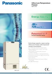
LIGHT STEP (ILLUMINANCE SETTING)The light step is for maintaining a constant illuminance within the chamber.The relationship between the light step (LS) and a number of fluorescent lamps to be lit is as follows:Light Step (LS) 0 1 2 3 4 5Fluorescent lamps to turn on 0 1 2 3 9 15The graph below shows the relationship between the light step setting, illuminance, and photosyntheticphoton flux density (PPFD) characteristics.Illuminance[Lx]30,000Fluorescent lamp: FL40SSENW37300PPFD[μmol・m -2 ・s -1 ]25,000(For EU)25020,00020015,000PPFDIlluminance15010,0001005,000External temperature: 20 o CInternal temperature: 25 o C50Measuring point: centerLight Step 0 1 2 3 4 5Illuminance[Lx]25,000Fluorescent lamp: FL40SS・W/37250PPFD[μmol・m -2 ・s -1 ]20,000(For the other areas)20015,00015010,000IlluminancePPFD1005,000External temperature: 20 o CInternal temperature: 25 o C50Measuring point: centerLight Step 01 2 3 4 5Caution:Type of the fluorescent lamp should be FL40SSENW37 (EU) or FL40SS・W/37 (the other areas). Othertype of lamp will affect on the power consumption and/or brightness.49
HUMIDITY CONTROL (<strong>MLR</strong>-<strong>352</strong>H ONLY)The chamber humidity can be set to any value within the range of 55 %R.H. to 90 %R.H.. RH though thekeys on the control panel. Input of any value outside of this range is invalid.The humidity control operates when the temperature setting is between the range 15 o C and 45 o C. Thedesired humidity may not be obtained if the temperature setting is outside of this range. Refer to thehumidity control range below. To disable the humidity control, enter a value of 00 %R.H. as the humiditysetting.The humidity control rangeAll fluorescent lamps OFF (LS 0)10090Humidity (%R.H.)80Controllable range70605040302010100908070605040302010All fluorescent lamps ON (LS 5)Controllable range010 20 30 40 50Set temperature ( o C)010 20 30 40 50Set temperature ( o C)CAUTIONThe humidity control is effective after the chamber temperature is stabilized between -1.5 o C and +2.5 o Cof the temperature setting. The humidity display shows a value greater than the humidity setting if thechamber temperature is outside of the range. This is not a malfunction.It takes much to reach the desired humidity if the chamber is wet or a large amount of load includinghumidity is placed in the chamber during low humidity operation.50
ROUTINE MAINTENANCEWARNINGAlways disconnect the power supply to the unit prior to any repair or maintenance of the unit inorder to prevent electric shock or injury.Ensure you do not inhale or consume medication or aerosols from around the unit at the time ofmaintenance. These may be harmful to your health.Cleaning of unit■ Clean the unit once a month. Regular cleaning keeps the unit looking new.■ Use a dry cloth to wipe off small amounts of dirt on the outside and inside of the unit and all accessories.After cleaning, wipe away the cleaner completely with a cloth washed in clean water.■ Put the removed all shelves back to the original position after cleaning. Make sure the air exhaustvent cover is set, too.■ Never splash water directly onto the unit. Deterioration of the insulation may result which could causefailure.■ The compressor and other mechanical part are completely sealed. This unit requires absolutely nolubrication.Replacement of fluorescent lampTotal 15 fluorescent lamps and glow starters are providedwith this unit. The glow starter is located beside theeach fluorescent lamp.Type of the fluorescent lamp is FL40SSENW37 (EU) orFL40SS・W/37 (the other areas). Another type of lampwill affect on the power consumption and/or brightness.1. Turn off the power switch, and disconnect the powersupply.FluorescentlampGlow starter2. Open the doors (front and side), take off blown lamp orglow starter.Note:■ Take care not to injure the fingers as the bulb can behot!■ Take care not to break the fluorescent lamp whendetaching it.■ Dispose a fluorescent lamp and a grow starter in accordance with the rule or the regulation of eachfacility or region.3. Set a fluorescent lamp or a glow starter.4. Connect the power supply, and turn on the power switch.51
ROUTINE MAINTENANCECleaning of evaporating trayThis tray catches defrosted water from evaporator and evaporates the water. Clean the tray with watertwice or 3 times a year. Refer to page 10 for taking out or replacing of the tray.Cleaning of filterThis product is provided with a condenser filter in the lower front. Clean the filter once a month since aclogged filter may cause shorter compressor life as well as the poor cooling.1. The filter is located in the left back of the front panel asshown in Fig. 1.Front panelFilterFig. 12. Takeout the filter. (Fig. 2)Fig. 23. Clean the filter by a vacuum cleaner and replace to the original position.Caution:Take care to set the filter all the way seated.52
ALARMS & SAFETY FUNCTIONSAutomatic set temperature alarmThe temperature alarm functions incorporated in this unit include automatic set temperature alarm otherthan high/low limit temperature alarm. This function operates when the chamber temperature deviatesfrom the set value by more than the alarm temperature (±1.0 o C ~ ±10.0 o C changeable). Thistemperature alarm activates as follows during the programmed running as well. For the details, seepage 54.Automatic set humidity alarm (<strong>MLR</strong>-<strong>352</strong>H only)For <strong>MLR</strong>-<strong>352</strong>H, the humidity alarm is operated when chamber humidity deviates from the set value bymore than the alarm humidify (±3 %R.H.~±15 %R.H. changeable). For the details, see page 54.Safety functionsThe unit has not only some alarm functions but also safety functions to keep the desired chambercondition. The details of the safety functions, see page 54, 55.Operation after power failureThe set value is memorized by nonvolatile memory. Accordingly, the chamber resumes the operationwith setting before power failure. During the power failure, the clock function is operating.■ In the clock mode, the operation resumes from the step (date and time) when power is recovered.Accordingly, the running step may be shorter than program.■ In the timer mode, the operation resumes with remained time before power failure. The time duringpower failure is not counted.53
ALARMS & SAFETY FUNCTIONSThis unit has the alarms and safety functions shown below, and also self diagnostic functions.Alarms & safety Situation Indication Buzzer Safety operationAutomatic settemperature alarmAutomatic sethumidity alarm(<strong>MLR</strong>-<strong>352</strong>H only)High limittemperature alarmLow limittemperature alarmPower failurealarmThe chamber temp. is out ofthe set value ± 2.5 o C.(±1.0 o C ~±10.0 o C changeable)Chamber temp. exceeds 20 o Cin during defrostingThe chamber humidity is out ofthe set value ±10 %R.H..(±3 %R.H.~±15 %R.H.changeable)The chamber temp. exceedsthe high limit temp. alarm setvalue (15 o C ~55 o C changeable).The chamber temp. exceedsthe low limit alarm temp. setvalue.(-10 o C ~25 o C changeable).When the power to the unit isdisconnected or power switchis turned OFF.The currentchamber temp.in the top screenblinks.The currentchamber humidityin the top screenblinksIntermittent tonewith the alarmdelay time delay----- Continuous tone----- Continuous toneRemote alarm withalarm delay timedelay.High alarm;heater OFFLow alarm;Compressor andcondensing fanmotor OFF----- -----Heater andfluorescent lamp OFFRemote alarmCompressor andcondensing fan motorOFFRemote alarm----- ----- Remote alarm.Thermal fuse Chamber temp. exceeds 70 o C ----- -----Thermal sensorabnormalityHumidity sensorabnormality(<strong>MLR</strong>-<strong>352</strong>H only)Filter alarmDefrost sensor(main evaporator)abnormalityInput voltage is lower thansuitability of -50 o CInput voltage is higher thansuitability of 70 o CInput voltage is lower thansuitability of 5 %R.H..Input voltage is higher thansuitability of 120 %R.H..The suction temp. of the filter ishigher than 50 o C or less.The sensor resistancecorresponds to -50 o C or less.The sensor resistancecorresponds to 70 o C or more.“Error 01: Tempsensor is opened.”is displayed in thetop screen.“Error 02: Tempsensor is shorted”is displayed in thetop screen.“Error 03: RHsensor level is low.”is displayed in thetop screen.“Error 04: RHsensor level is over”is displayed in thetop screen.“Filter” is displayedin the top screen.“Error 05: Defsensor is opened”is displayed in thetop screen.“Error 06: Defsensor is shorted”is displayed in thetop screen.Intermittent toneIntermittent toneFusingHeater OFFHeater,Fluorescent lamp,condensing fan motorand compressor OFFRemote alarmHumidity control OFFRemote alarm----- -----Intermittent toneMain heater OFF(when the chambertemp. reaches 16 o C)Remote alarm54
Alarms & safety Situation Indication Buzzer Safety operationDefrost sensor(sub evaporator)Abnormality(<strong>MLR</strong>-<strong>352</strong>H only)Filter sensorabnormalityDoor alarmRunning programback-upClock functionback-upInner fan motoralarmCondensing fanmotor alarmThe sensor resistancecorresponds to -50 o C or less.The sensor resistancecorresponds to 70 o C or more.The sensor resistancecorresponds to -50 o C or less.The sensor resistancecorresponds to 70 o C or more.The door is open during morethan door delay time.(default: 2 minutes)“Error 07: Def.Ssensor is opened”is displayed in the topscreen.“Error 08: Def.Ssensor is shorted”is displayed in the topscreen.“Error 11: Filtersensor is opened”is displayed in the topscreen.“Error 12: Filtersensor is shorted”is displayed in the topscreen.When door is opened;“Door” is highlighted.After door alarm delaytime;“Door” is displayedalternately in normalcharacters andreverse videoin the top screen.Intermittent toneIntermittent toneIntermittent toneDuring power failure ----- -----During power failure ----- -----The inner fan motorbreaks down.The condensing fan motorbreaks down.“Error 09: Cooling fanmotor trouble”is displayed in the topscreen.“Error 10: Condensingfan motor trouble”is displayed in the topscreen.Intermittent toneIntermittent toneSub evaporatorheater OFFDefrost OFFRemote alarmRemote alarmWhen the door isopened;Inner fan OFFNonvolatile memoryResumes runningafter power recoveryContinuous runningby a battery (CR2032)Heater,fluorescent lamp,condensing fan motorand compressor OFFRemote alarmHeater,fluorescent lamp andcompressor OFFRemote alarmNote:■ The buzzer of alarms other than the high limit temperature alarm and the low limit temperature alarmcan be silenced by pressing the alarm buzzer stop key (BUZZER).■ The buzzer will be activated again after the certain suspension if the alarm condition is continued aftersilencing the buzzer. The suspension time after silencing the buzzer and before resuming the buzzercan be set by "Ring Back". Refer to page 44.■ The buzzer will be activated again after the certain suspension if the door is kept opened, after silencingthe buzzer. The suspension time after silencing the buzzer and before resuming the buzzer can be setby "Door ring Back". Refer to page 44.■ To stop the buzzer of the high limit temperature alarm and the low limit temperature alarm, change thesetting temperature of each alarm to avoid the current operating temperature. Need to be set thembeyond ±5 o C of operating temperature range.55
TROUBLESHOOTINGIf the unit malfunctions, check out the following before calling for service.MalfunctionCheck/RemedyNothing operates even ■ The unit is not connected to the power supply or capacity of powerwhen switched onsource is not enough.■ There is a power failure, the fuse is blown, or the circuit breaker isactivated.Alarm is activated■ Chamber temperature exceeds high limit/low limit temperature alarmtemperature.In this case, check the chamber temperature setting, and high/low limittemperature alarm. When the chamber temperature is not set betweenhigh and low limit temperature alarm, it is necessary to reset either highor low limit alarm temperature.■ A lot of heat load is placed in the chamber at once.In this case, the alarm is eliminated when the chamber temperaturegoes down.■ There is a excessive heat source in the chamber.Refer to next page for the acceptable limits for heat load in the chamber.■ Is the unit operating beside the appliance that generates theelectromagnetic wave?The temperature is not ■ The programmed temperature variation is over the pull up/pull downchanged according to a performance of the unit.programThe performance of the unit is shown on next page. It takes much timeto pull up/pull down when some items are placed in the chamber. Set aprogram taking the performance into consideration.■ The setting of high/low limit temperature alarm is not correct.■ Is the unit operating beside the appliance that generates theelectromagnetic wave?Note:If the malfunction is not eliminated after checking the above items, or the malfunction is not shown in theabove table, contact our sales representative or agent.Keep an electric product which emits an electromagnetic wave away from this product. A noise from anelectromagnetic wave may cause malfunction of the product.56
DISPOSAL OF UNITWARNINGIf the unit is to be stored unused in an unsupervised area for an extended period ensure that childrendo not have access and doors cannot be closed completely.The disposal of the unit should be accomplished by appropriate personnel. Always removedoors to prevent accidents such as suffocation.57
DISPOSAL OF UNITNote:This symbol mark and recycle system are applied only to EU countriesand not applied to the countries in the other area of the world.Waste Electrical and Electronic Equipment (WEEE) Directive-2002/96/EC(English)Your <strong>Panasonic</strong> product is designed and manufactured with high quality materials and components whichcan be recycled and reused.This symbol means that electrical and electronic equipment, at their end-of-life, should be disposed ofseparately from your household waste.Please dispose of this equipment at your local community waste collection/recycling centre.In the European Union there are separate collection systems for used electrical and electronic products.Please help us to conserve the environment we live in!(German)Ihr <strong>Panasonic</strong> Produkt wurde entworfen und hergestellt mit qualitativ hochwertigen Materialien undKomponenten, die recycelt und wiederverwendet werden können.Dieses Symbol bedeutet, daß elektrische und elektronische Geräte am Ende ihrer Nutzungsdauer vonHausmüll getrennt entsorgt werden sollen.Bitte entsorgen Sie dieses Gerät bei Ihrer örtlichen kommunalen Sammelstelle oder im Recycling Centre.In der Europäischen Union gibt es unterschiedliche Sammelsysteme für Elektrik- und Elektronikgeräte.Helfen Sie uns bitte, die Umwelt zu erhalten, in der wir leben!58
(French)Votre produit <strong>Panasonic</strong> est conçu et fabriqué avec des matèriels et des composants de qualité supérieurequi peuvent être recyclés et réutilisés.Ce symbole signifie que les équipements électriques et électroniques en fin de vie doivent être éliminésséparément des ordures ménagères.Nous vous prions donc de confier cet équipement à votre centre local de collecte/recyclage.Dans l’Union Européenne, il existe des systèmes sélectifs de collecte pour les produits électriques etélectroniques usagés.Aidez-nous à conserver l’environnement dans lequel nous vivons !Les machines ou appareils électriques et électroniques contiennent fréquemment des matières qui, si ellessont traitées ou éliminées de manière inappropriée, peuvent s’avérer potentiellement dangereuses pour lasanté humaine et pour l’environnement.Cependant, ces matières sont nécessaires au bon fonctionnement de votre appareil ou de votre machine.Pour cette raison, il vous est demandé de ne pas vous débarrasser de votre appareil ou machine usagéavec vos ordures ménagères.(Spanish)Los productos <strong>Panasonic</strong> están diseñados y fabricados con materiales y componentes de alta calidad,que pueden ser reciclados y reutilizados.Este símbolo significa que el equipo eléctrico y electrónico, al final de su ciclo de vida, no se debedesechar con el resto de residuos domésticos.Por favor, deposite su viejo “televisor” en el punto de recogida de residuos o contacte con suadministración local.En la Unión Europea existen sistemas de recogida específicos para residuos de aparatos eléctricos yelectrónicos.Por favor, ayúdenos a conservar el medio ambiente!59
DISPOSAL OF UNIT(Portuguese)O seu produto <strong>Panasonic</strong> foi concebido e produzido com materiais e componentes de alta qualidade quepodem ser reciclados e reutilizados.Este símbolo significa que o equipamento eléctrico e electrónico no final da sua vida útil deverá serdescartado separadamente do seu lixo doméstico.Por favor, entregue este equipamento no seu ponto local de recolha/reciclagem.Na União Europeia existem sistemas de recolha separados para produtos eléctricos e electrónicosusados.Por favor, ajude-nos a conservar o ambiente em que vivemos!(Italian)Il vostro prodotto <strong>Panasonic</strong> è stato costruito da materiali e componenti di alta qualità, che sonoriutilizzabili o riciclabili.Prodotti elettrici ed elettronici portando questo simbolo alla fine dell’uso devono essere smaltitiseparatamente dai rifiuti casalinghi.Vi preghiamo di smaltire questo apparecchio al deposito comunale.Nell’Unione Europea esistono sistemi di raccolta differenziata per prodotti elettrici ed elettronici.Aiutateci a conservare l’ambiente in cui viviamo!60
(Dutch)<strong>Panasonic</strong> producten zijn ontwikkeld en gefabriceerd uit eerste kwaliteit materialen, de onderdelen kunnenworden gerecycled en weer worden gebruikt.Het symbool betekent dat de elektrische en elektronische onderdelen wanneer deze vernietigd gaanworden , dit separaat gebeurt van het normale huisafval.Zorg ervoor dat het verwijderen van de apparatuur bij de lokaal erkende instanties gaat gebeuren.In de Europese Unie wordt de gebruikte elektrische en elektronische apparatuur bij de daarvoor wettelijkeinstanties aangeboden.Alstublieft help allen mee om het milieu te beschermen.(Swedish)Din <strong>Panasonic</strong> produkt är designad och tillverkad av material och komponenter med hög kvalitet som kanåtervinnas och återanvändas.Denna symbol betyder att elektriska och elektroniska produkter, efter slutanvändande, skall sorteras ochlämnas separat från Ditt hushållsavfall.Vänligen, lämna denna produkt hos Din lokala mottagningstation för avfall/återvinningsstation.Inom den Europeiska Unionen finns det separata återvinningssystem för begagnade elektriska ochelektroniska produkter.Vänligen, hjälp oss att bevara miljön vi lever i!61
PERFORMANCE DATA (<strong>MLR</strong>-<strong>352</strong>H)1. Pull down, pull up performance (The chamber temperature of center)Ambient temperature: 20 o CPOWER: 50 HzFluorescent lampOFF15 fluorescentlamps turn on2. Acceptable heat load inside a chamberThe maximum heat load being possible to maintain the setting temperature varies depending on theambient temperature and the number of fluorescent lamp lighting. Refer to the following graph andobserve the heat load permitted within the chamber.*1: When the setting temperature is higher than 5 o C or more. If not, the chamber temperature may notreach the setting temperature.*2: When the setting temperature is higher than 10 o C or more. If not, the chamber temperature may notreach the setting temperature.62
SPECIFICATIONSProduct nameExternal dimensionsInternal dimensionsEffective capacityExteriorInteriorDoorInner doorInsulationShelfAccess portHeating and cooling methodCompressorEvaporatorCondenserRefrigerantDefrostingVersatile Environmental Test Chamber<strong>MLR</strong>-<strong>352</strong>W760 mm x D700 mm x H1835 mmW520 mm x D490 mm x H1135 mm294 LPainted steelVersatile Environmental Test Chamber<strong>MLR</strong>-<strong>352</strong>HStainless steel, Paired glass window on right and left side (370 mm x 1110 mm)Painted steel, front, left, and right sidePaired glassRigid polyurethane foamed-in placeHard steel wire on polyester coating, 4 pcs.Inner dimension; W465 mm x D450 mm, Maximum load; 25 kg/shelfHard steel wire on polyester coating with stainless cover, 1 pc. (bottom)Inner dimension; W355 mm x D395 mm, Maximum load; 25 kg/shelfInner diameter; 40 mm, Top left sideForced air circulationHermetic type, Output; 250 WFin and tube typeFin and tube typeR-404AAutomatic defrost (3 patterns), Manual defrostHeater 334 W 381 WTemperature controllerTemperature displayElectric heat apparatus: PID control, Compressor: ON-OFF controlDigital displayHumidity controller ---Electronic expansion valve: PID controlHumidifier: PI controlHumidity display --- Digital displayAlarms and safety functionsRemote alarm contactProgram functionOvercurrent protectorAccessoriesAutomatic set temperature alarm, High/Low limit temperature alarm,Filter alarm, Temperature/Filter/Defrost (main evaporator) sensor alarm,Inner/Condensing fan motor alarm, Door alarm, Thermal fuse,Memory back-upAutomatic set humidity alarm,---Humidity sensor alarmDefrost (sub evaporator) sensor alarmDC 30 V, 2 ATemperature, illuminanceTemperature, illuminance, humidity12 steps (10 patterns), 98 cycle or limitlessClock mode: 00:00~23:59Timer mode: 00:01~99:594 upper shelves, 1 bottom shelf,1 air exhaust vent coverRated current: 25 A4 upper shelves, 1 bottom shelf,1 air exhaust vent cover,1 water supply tank, 1 supply hoseWeight 226 kg 235 kgData acquisition system (MTR-5000)OptionInterface board (MTR-L03), Interface board (MTR-480)Note: Refer to the updated catalog when ordering an optional component.Designs and specifications are subject to change without notice.63
PERFORMANCEProduct nameVersatile Environmental Test Chamber <strong>MLR</strong>-<strong>352</strong>Model No. <strong>MLR</strong>-<strong>352</strong>-PK <strong>MLR</strong>-<strong>352</strong>-PB <strong>MLR</strong>-<strong>352</strong>-PETemperature setting rangeTemperature control range0 o C to +50 o C+10 o C to +50 o C (light ON), 0 o C to +50 o C (light OFF)Temperature distribution±3.5 o C (light ON), ±1.5 o C (light OFF)(Ambient temperature: 20 o C, no load)±2.5 o C (light ON), ±1.0 o C (light OFF)(Set temperature: 25 o C, ambient temperature: 20 o C, no load)Temperature fluctuation±0.3 o C (Set temperature: 25 o C, ambient temperature: 20 o C, no load)Fluorescent light40 W x 15 (FL40SS・W/37)Glow starter x 15 (FG-4P)40 W x 15 (FL40SSENW37)Glow starter x 15 (FG-4P)Brightness control range0~20000 Lx(Photosynthetic photon flux density:150 μmol・m -2 ・s -1 )6 steps changeable0~20000 Lx(Photosynthetic photon flux density:250 μmol・m -2 ・s -1 )6 steps changeableUsable ambient temperature+5 o C to +35 o C, Less than 80 %R.H.Noise level47 dB (light ON) / 45 dB (light OFF) (A scale)Maximum pressure2950 kPaRated voltage AC 220 V AC 230 V/240 VRated frequency 60 Hz 50 HzPower consumption 1440 W 1300 W 1400 W/1500 WProduct nameVersatile Environmental Test Chamber <strong>MLR</strong>-<strong>352</strong>HModel No. <strong>MLR</strong>-<strong>352</strong>H-PA <strong>MLR</strong>-<strong>352</strong>-PK <strong>MLR</strong>-<strong>352</strong>H-PB <strong>MLR</strong>-<strong>352</strong>H-PETemperature setting rangeTemperature control rangeTemperature distributionTemperature fluctuationFluorescent lightBrightness control rangeHumidity setting range0 o C to +50 o C+10 o C to +50 o C (light ON), +5 o C to +50 o C (light OFF)±3.5 o C (light ON), ±1.5 o C (light OFF)(Ambient temperature: 20 o C, no load)±2.5 o C (light ON), ±1.0 o C (light OFF)(Set temperature: 25 o C, ambient temperature: 20 o C, no load)±0.3 o C (Set temperature: 25 o C, ambient temperature: 20 o C, no load)40 W x 15 (FL40SS・W/37)Glow starter x 15 (FG-4P)40 W x 15 (FL40SSENW37)Glow starter x 15 (FG-4P)0~20000 Lx0~20000 Lx(Photosynthetic photon flux density: (Photosynthetic photon flux150 μmol・m -2 ・s -1 )density: 250 μmol・m -2 ・s -1 )6 steps changeable6 steps changeable55 %R.H. to 90 %R.H. or OFFHumidity control range 60 %R.H. to 90 %R.H. (at LS: 0 and Temperature: +15 o C to +45 o C)55 %R.H. to 85 %R.H. (at LS: 5 and Temperature: +15 o C to +45 o C)Usable ambient temperature+5 o C to +35 o C, Less than 80 %R.H.Noise level47 dB (light ON) / 45 dB (light OFF) (A scale)Maximum pressure2950 kPaRated voltage AC 115 V AC 220 V AC 230 V/240 VRated frequency 60 Hz 50 HzPower consumption 1450 W 1450 W 1310 W 1500 W/1550 WNote: Design or specification will be subject to change without notice.The unit with CE mark complies with EC directives.64
CAUTIONPlease fill in this form before servicing.Hand over this form to the service engineer to keep for his and your safety.Safety check sheet1. Chamber contents :Risk of infection:Risk of toxicity:Risk from radioactive sources:□Yes□Yes□Yes□No□No□No(List all potentially hazardous materials that have been stored in this unit.)Notes :2. Contamination of the unitUnit interiorNo contaminationDecontaminatedContaminatedOthers:□Yes□Yes□Yes□No□No□No3. Instructions for safe repair/maintenance of the unita) The unit is safe to work onb) There is some danger (see below)□Yes□Yes□No□NoProcedure to be adhered to in order to reduce safety risk indicated in b) below.Date :Signature :Address, Division :Telephone :Product name:Versatile EnvironmentalTest ChamberModel No.<strong>MLR</strong>-Serial number:Date of installation:Please decontaminate the unit yourself before calling the service engineer.65
1-1-1 Sakata, Oizumi-Machi, Ora-Gun, Gunma 370-0596, Japan© <strong>Panasonic</strong> Healthcare Co., Ltd. 2012Printed in Japan7FB6P151616002S0512-20812