Sonos Voice Sounder - Klaxon Signals Ltd.
Sonos Voice Sounder - Klaxon Signals Ltd.
Sonos Voice Sounder - Klaxon Signals Ltd.

Create successful ePaper yourself
Turn your PDF publications into a flip-book with our unique Google optimized e-Paper software.
<strong>Sonos</strong> and Nexus <strong>Voice</strong> <strong>Sounder</strong>sUser Guide1
Table of Contents<strong>Sonos</strong> <strong>Voice</strong> <strong>Sounder</strong> (<strong>Sounder</strong> Only Operation) ------------------------------------ 3Nexus DC <strong>Voice</strong> <strong>Sounder</strong> (<strong>Sounder</strong> Only Operation) ------------------------------- 4Nexus AC <strong>Voice</strong> <strong>Sounder</strong> (<strong>Sounder</strong> Only Operation) -------------------------------- 6<strong>Sonos</strong> <strong>Voice</strong> <strong>Sounder</strong> (with Interface Control Unit) ---------------------------------- 8Nexus 2-Wire <strong>Voice</strong> <strong>Sounder</strong> Beacon (with Interface Control Unit) --------------- 10Fire Alarm Interface Control Unit ------------------------------------------------------ 12Gas Eextinguishing Interface Control Unit --------------------------------------------- 15Industrial Interface Control Unit ------------------------------------------------------- 182
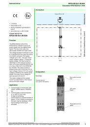
<strong>Sonos</strong> <strong>Voice</strong> <strong>Sounder</strong> (<strong>Sounder</strong> Only Operation)Technical SpecificationSupply Voltage Range17-32V DCCurrent30mAPeak Sound Level: 94-106 dBA at 1m*Number of Tones: 32Number of Messages 3Frequency Range400-2850 Hz*Operating Temperature:- 25°C to +70°CCasing:High Impact PolycarbonateIP Rating:IP65 (with deep base)SynchronisationAutomatic with <strong>Klaxon</strong> <strong>Sonos</strong> and Nexus <strong>Voice</strong>-Enhanced <strong>Sounder</strong>s*depends on selected tone and input voltage. See tone table for details.InstallationIf required, the mechanism for locking the sounder to the base can be activated by removing the thin section ofplastic shown in Fig. 1 with side cutters or a similar tool. To open a locked head, remove the small white bungfrom the hole on the side of the sounder, insert a tool into the hole and depress the clip whilst twisting the head.The O-ring and bung must be re-fitted to maintain the weatherproofing.Fig.1 Remove tabto lock sounderWiringSignal Positive Supply Negative Supply1 st Stage Message (3) IN+ (2) or COM -2 nd Stage Message (3) IN+ (1) ♫/3 rd Stage Message (3) IN+ (1) ♫/ AND (2) or COM A separate earth terminal is provided on the deep base for connecting the screen or functional earth. On theshallow base, terminal 5 can be used for this purpose.Alerting Tone Selection and Volume Controla. The alerting tone sounds for 4 seconds before the speech message plays and is selected using the 5 waydipswitch on the bottom of the sounder head. Refer to the table overleaf for details of the available tones andthe switch settings required to select them.b. The sound output of the unit can be reduced by adjusting the potentiometer on the bottom of the sounder.3
_+_+Nexus DC <strong>Voice</strong> <strong>Sounder</strong> (<strong>Sounder</strong> Only Operation)Technical SpecificationSupply Voltage Range:17-28V DCCurrent – <strong>Sounder</strong>:30mACurrent – Beacon (where fitted): Xenon - 250mA Average, 700mA Peak*,LED - 18mA (Flashing) or 65mA (Static)*Peak Sound Level: 104-116 dBA at 1m* (Typ. 110dBA @ 24V, Tone 1)Frequency Range:400-2900 Hz*Operating Temperature: - 25°C to +70°CVolume Control20dBA typicalRemote Message Switching Provision for up to 7 messages (Negative voltage activation)Casing:High Impact Polycarbonate/ABSIP Rating:IP66SynchronisationAutomatic with <strong>Klaxon</strong> Nexus and <strong>Sonos</strong> <strong>Voice</strong>-Enhanced <strong>Sounder</strong>s*depends on selected tone and supply voltageInstallationa. The sounder is installed by first mounting the base unit and making the external wring connections to thebase. The head unit then automatically connects when it is attached to the base.]b. The sounder head is separated from the base by unlocking the four ¼-turn fasteners in the corners of thesounder.c. Note that the head only fits onto the base one way around. If a beacon is fitted, care should be taken whenmounting the base to ensure that the beacon will be positioned in the desired orientation after the sounder isattached.WiringFrom controllerTo next unitBeacon+-<strong>Sounder</strong>+-1. Stage2. Stage3. StageS3S2_+_+S3S2_+_+1. Unit 2. UnitThe siren has seven selectable stages. These stages are selected by connecting the negative of yourpower supply (0V) to any combination of the , or terminal block connectionsThe positive lead of the power supply (24V) always wires to the terminal block connection.4
The sounder and beacon have separate wiring terminals. Each terminal is duplicated to enable simple ‘daisychain’connection of multiple units.Line<strong>Sounder</strong> Positive Supply (17 to 28V DC)<strong>Sounder</strong> Negative Supply (0V)<strong>Sounder</strong> Negative Supply (0V)<strong>Sounder</strong> Negative Supply (0V)Beacon Positive Supply (17 to 28V DC)Beacon Negative Supply (0V)Terminal MarkingSelection of the message the sounder plays is controlled by the combination of three negative supply connectionsas follows:Connections to Supply NegativeMessageNo. Typical UseOpen Open Open 0 OffOpen Open Closed 1 AlertOpen Closed Open 2 EvacuateOpen Closed Closed 3 TestClosed Open Open 4 All ClearClosed Open Closed 5 (Free)Closed Closed Open 6 (Free)Closed Closed Closed 7 (Free)Configuration and Controla. MessagesThe sounder is supplied pre-programmed with up to seven voice messsages. The stored messages can bere-programmed via the USB interface using a Windows PC. Refer to the separate programming guide fordetails.jb. Alerting ToneThe accompanying tone for each message can be selected via the programming software. The alertingtone sounds for 3 seconds before the speech message plays. If required, alternative tones can be selectedusing a PC and the USB interface.c. Volume ControlThe sound output of the unit can be reduced by adjusting the potentiometer.d. Beacon Flash Controls (If fitted)The flash mode of the beacon can be altered using the 2-way dipswitch markedXENON BEACONLED BEACONSwitch Off On Off On1 60 flashes per minute 30 flashes perminuteSingle Flash DoubleFlash2 Single Flash Double Flash Flashing Static5
Nexus AC <strong>Voice</strong> <strong>Sounder</strong> (<strong>Sounder</strong> Only Operation)Technical SpecificationSupply Voltage Range:110 or 230V AC 50/60Hz CCurrent<strong>Sounder</strong> - 30mA maxBeacon (Where fitted) - 70mAPeak Sound Level: 103-115 dBA at 1m*Frequency Range:400-2900 Hz*Operating Temperature:- 25°C to +55°CVolume Control20dBA typicalRemote Message Switching Provision for 4 volt-free contact activated alarm stagesCasing:High Impact Polycarbonate/ABSIP Rating:IP66SynchronisationAutomatic with <strong>Klaxon</strong> Nexus and <strong>Sonos</strong> <strong>Voice</strong>-Enhanced<strong>Sounder</strong>s*depends on selected tone and supply voltageInstallationIMPORTANTa. The unit should be fitted with a fused spur incorporating an all pole disconnection deviceproviding 3mm contact separation in all poles. Ensure fuse, cable size and gland type arerated sufficiently for the total load on the sounder circuit.b. Isolate the unit from the electricity supply before removing the cover. Only suitably qualifiedpersonnel should gain access to the unit to perform adjustments to the tone or volume.WARNING: no user serviceable parts contained within the unit.c. The sounder is installed by first mounting the base unit and making the external wringconnections to the base. The head unit then automatically connects when it is attached to thebase.d. The sounder head is separated from the base by unlocking the four ¼-turn fasteners in thecorners of the sounder. (Recommended screwdriver: Philips No. 2, min 100mm long).e. Note that the head only fits onto the base one way around. If a beacon is fitted, care should betaken when mounting the base to ensure that the beacon will be positioned in the desiredorientation after the sounder is attached.6
-+-+WiringFrom controllerBeacon L<strong>Sounder</strong> LCommon NTo next unit2. Stage3. StageS3 S2 0N110V~230V~230V~110V~S3 S2 0N110V~230V~230V~110V~1. Unit 2. Unita. Power: Note that the sounder and beacon have separate power terminals, marked as follows:Device Common (Neutral) 110V AC 230V AC<strong>Sounder</strong>Beacon (Where fitted)b. Remote Message Switching (If required): Externally link control terminals (S2 and S3) tocommon terminal (marked ) as shown below.Connection to TerminalMessageNo. Typical UseOpen Open 1 AlertOpen Closed 2 EvacuateClosed Open 3 All ClearClosed Closed 4 TestConfiguration and Controla. MessagesThe sounder is supplied pre-programmed with up to four voice messsages. The storedmessages can be re-programmed via the USB interface using a Windows PC. Refer to theseparate programming guide for details.jb. Alerting ToneThe accompanying tone for each message can be selected via the programming software. Thealerting tone sounds for 3 seconds before the speech message plays. If required, alternativetones can be selected using a PC and the USB interface.c. Volume ControlThe sound output of the unit can be reduced by adjusting the potentiometer.7
<strong>Sonos</strong> <strong>Voice</strong> <strong>Sounder</strong> (with Interface Control Unit)Technical SpecificationSupply Voltage Range 17-28V DCCurrent30mAPeak Sound Level: 94-106 dBA at 1m*Number of MessagesProvision for up to 7 messagesFrequency Range400-2850 Hz*Operating Temperature: - 25°C to +70°CCasing:High Impact PolycarbonateIP Rating:IP65 (with deep base)SynchronisationAutomatic with <strong>Klaxon</strong> <strong>Sonos</strong> and Nexus <strong>Voice</strong>-Enhanced <strong>Sounder</strong>s*depends on selected tone and input voltage. See tone table for details.InstallationIf required, the mechanism for locking the sounder to the base can be activated byremoving the thin section of plastic shown in Fig. 1 with side cutters or a similar tool. Toopen a locked head, remove the small white bung from the hole on the side of the sounder,insert a tool into the hole and depress the clip whilst twisting the head. The O-ring and bungmust be re-fitted to maintain the weatherproofing.Fig.1 Remove tabto lock sounderWiringLineTerminal Marking<strong>Sounder</strong> Positive Supply (17 to 28V DC)(3) IN+<strong>Sounder</strong> Negative Supply (0V) (2) or COM -A separate earth terminal is provided on the deep base for connecting the screen orfunctional earth. On the shallow base, terminal 5 can be used for this purpose.(Selection of the message the sounder plays is controlled by the <strong>Klaxon</strong> MessageInterface Unit.)8
Alerting Tone Selection and Volume Controla. The alerting tone sounds for 3 seconds before the speech message plays. It canbe changed using the 5 way dipswitch on the bottom of the sounder head.Switches 1 and 2 alter the Alert/1 st Stage tone. Switches 3 and 4 alter all othertones.b. The sound output of the unit can be reduced by adjusting the potentiometer onthe bottom of the sounder.c. Beacon Flash Controls:If switch 5 is ON then the beacon will not flash after Alert/1 st Stage is over.9
Nexus 2-Wire <strong>Voice</strong> <strong>Sounder</strong> Beacon (with Interface ControlUnit)Technical Specification:Supply Voltage Range: 17-28V DCCurrent – <strong>Sounder</strong>:50mAPeak Sound Level: 104-116 dBA at 1m* (Typ. 110dBA @ 24V,Tone 1)Frequency Range:400-2900 Hz*Operating Temperature: - 25°C to +70°CVolume Control20dBA typicalRemote Message Switching Provision for up to 7 messagesCasing:High Impact Polycarbonate/ABSIP Rating:IP66SynchronisationAutomatic with <strong>Klaxon</strong> Nexus and <strong>Sonos</strong> <strong>Voice</strong>-Enhanced <strong>Sounder</strong>s*depends on selected tone and supply voltageInstallationa. The sounder is installed by first mounting the base unit and making the externalwring connections to the base. The head unit then automatically connects when itis attached to the base.b. The sounder head is separated from the base by unlocking the four ¼-turnfasteners in the corners of the sounder.c. Note that the head only fits onto the base one way around. If a beacon is fitted,care should be taken when mounting the base to ensure that the beacon will bepositioned in the desired orientation after the sounder is attached.WiringEach terminal is duplicated to enable simple ‘daisy-chain’ connection of multiple units.Line<strong>Sounder</strong> Positive Supply (17 to 28V DC)<strong>Sounder</strong> Negative Supply (0V)Terminal MarkingSelection of the message the sounder plays is controlled by the <strong>Klaxon</strong> Message InterfaceUnit.Configuration and Controla. MessagesThe sounder is supplied pre-programmed with up to seven voice messsages. Thestored messages and tones can be re-programmed via the USB interface using a10
Windows PC. Refer to the separate programming guide for details.jb. Alerting ToneThe alerting tone sounds for 3 seconds before the speech message plays. It can bechanged using the 5 way dipswitch on the bottom of the sounder head. Switches 1 and2 alter the Alert/1 st Stage tone. Switches 3 and 4 alter all other tones.c. Volume ControlThe sound output of the unit can be reduced by adjusting the potentiometer.d. Beacon Flash ControlsIf switch 5 is ON then the beacon will not flash after Alert/1 st Stage is over. The flashmode of the beacon can be altered using the PC Software (supplied on CD).11
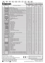
Fire Alarm Interface Control UnitTechnical SpecificationSupply Voltage Range:Current:Remote Tone Switching:Operating Temperature:Casing:17-28V DC45mA (active alarm), 16mA (quiescent)Provision for 4 alarm stages (plus a default warningstage)- 25°C to +70°CPolycarbonateInstallationa. The interface connects a fire alarm panel to <strong>Klaxon</strong>’s <strong>Voice</strong>-Enhanced Nexus/<strong>Sonos</strong>sounders.b. The interface takes its supply (‘+AUX-’) from the 24V Auxiliary Output from the panel.c. The <strong>Sounder</strong> 1 (1 st Stage <strong>Sounder</strong>) Output of the fire alarm panel should be connectedto the ‘+SND1-’ input terminals of the interface.d. The <strong>Sounder</strong> 2 (2 nd Stage <strong>Sounder</strong>) Output from the fire alarm panel should beconnected to the ‘+SND2-’ input terminals of the interface.e. The <strong>Voice</strong>-Enhanced sounders are then connected to the ‘+O/P1-’ and/or ‘+O/P2-’terminals of the controller. Each chain of sounders should be terminated with the endof-lineresistor specified for the fire alarm panel being used.WiringNote: If using only one Panel <strong>Sounder</strong> Output then make sure that you wire into SND2. If theinterface develops a fault or loses power a safety relay switches a 1KΩ resistor onto OP212
In none-alarm condition the SND1 and SND2 inputs are connected to the OP1 and OP2outputs. The Panel uses reverse monitoring when looking at the EOL Resistors.An Alarm condition switches two relays to disconnect OP1 and OP2 from the SND inputs andconnects the panel to the Stg1 and Stg2 dummy EOL resistors.Messages• If there is a Loss of Power or an interface fault a default message of your choice isplayed.• When AL1 (or AL2) receive a pulsed voltage (Dependant on Panel functionality) theinterface takes control of the sounders from the Panel and initiates an ‘Alert’message.• When AL1 (or AL2) receive a static or constant voltage (in normal alarm condition)the interface then initiates the ‘Evacuate’ message• If the Key-switch on the interface unit is switched to the Test position and an alarmcondition is detected the ‘Test’ message is played.• If the Key-switch is turned to the Normal position the ‘Alarm Test Over’ message isplayed.ControlsFire Panel SelectionmThe interface controller will work with all common types of fire panel. There is a 5-waydipswitch inside the interface that is used to describe the fire panel being connected to.N.B. These switches must be set before power is applied to the ‘+AUX-’ inputs of the <strong>Klaxon</strong>controller; the controller will not acknowledge switch changes after power has been applied.DIP 5 ONDIP 3 OFF &Alert: 0.5s ON/ 0.5s OFFDIP 4 OFF:DIP 3 OFF &Alert: 1s ON/ 1s OFFDIP 4 ON:DIP 3 ON &Alert: 2s ON/ 2s OFFDIP 4 OFF:DIP 1 and DIP 2 have no effect (please leave OFF)Standard Fire ModeIn FIRE mode (DIP 5 ON) only the ‘+SND2-’ input is read by the interface unit. If you only wantto use one sounder circuit then ‘+SND2-’ and ‘+O/P2-’ should be used (‘+SND1-’ can be leftdisconnected).Fault IndicationShould a fault occur (e.g. damage, loss of power, etc.) the interface unit places a 1kΩ resistoracross the ‘+SND2-’/‘+O/P2-’ terminals. This will induce a sounder circuit ‘overload’ or ‘shortcircuit’fault at the fire alarm panel.13
End-of-Line ResistanceUnder quiescent conditions the ‘+SND2-’ terminals are connected directly to the ‘+O/P2-’terminals. Similarly, the ‘+SND1-’ terminals are connected directly to the ‘+O/P1-’ terminals.This allows the fire alarm panel to monitor the sounder circuits as normal. Each sounder circuitshould be terminated with the end-of-line resistor specified in the panel installation manual.In an alarm condition (e.g. ‘alert’, ‘evacuate’, etc.) the interface unit breaks the connectionsbetween the ‘+SND-’ input terminals and the ‘+O/P-’ output terminals. The interface unit thenhas its own connection to the sounder circuit(s).N.B. During this time the fire alarm panel will no longer be able to ‘see’ the actual end-of-lineresistors.You should place ‘dummy’ end-of-line resistors in the terminals marked ‘STG2 EOL’ and ‘STG1EOL’. The values of these resistors will be the same as the end-of-line resistors used at the end ofthe sounder circuit(s).14
Gas Eextinguishing Interface Control UnitTechnical SpecificationSupply Voltage Range:Current:Remote Tone Switching:Operating Temperature:Casing:17-28V DC45mA (active alarm), 16mA (quiescent)Provision for 4 alarm stages (plus a default warningstage)- 25°C to +70°CPolycarbonateInstallationa. The interface connects a gas extinguishing control panel to <strong>Klaxon</strong>’s <strong>Voice</strong>-EnhancedNexus/<strong>Sonos</strong> sounders.b. The interface takes its supply (‘+AUX-’) from the 24V Auxiliary Output from thepanel.c. The <strong>Sounder</strong> 1 (1 st Stage <strong>Sounder</strong>) Output of the gas panel should be connected to the‘+SND1-’ input terminals of the interface.d. The <strong>Sounder</strong> 2 (2 nd Stage <strong>Sounder</strong>) Output from the gas panel should be connected tothe ‘+SND2-’ input terminals of the interface.e. The <strong>Voice</strong>-Enhanced sounders are then connected to the ‘+O/P1-’ and/or ‘+O/P2-’terminals of the controller. Each chain of sounders should be terminated with the endof-lineresistor specified for the gas panel being used.WiringIn none-alarm condition the SND1 and SND2 inputs are connected to the OP1 and OP2 outputs.The Panel uses reverse monitoring when looking at the EOL Resistors.15
An Alarm condition switches two relays to disconnect OP1 and OP2 from the SND inputs andconnects the panel to the Stg1 and Stg2 dummy EOL resistors.Messagesa. If there is a Loss of Power or an interface fault a default message is played.b. When a pulsed signal is transmitted on Stage1 input the interface takes control of thesounders from the Panel and initiates the Stage1 or ‘Alert’ message.c. When a pulsed signal is transmitted on Stage2 input the Stage2 ‘Gas Releaseimminent’ message is played.d. When there is a constant voltage applied to Stage1 the ‘Hold Off’ message is playede. When there is a constant voltage applied to Stage2 the ‘Gas released’ message isplayed.ControlsGas Extinguihing Panel SelectionmThe interface controller will work with all common types of Gas Extiguishing panel. There is a 5-way dipswitch inside the interface that is used to describe the gas panel being connected to.N.B. These switches must be set before power is applied to the ‘+AUX-’ inputs of the <strong>Klaxon</strong>controller; the controller will not acknowledge switch changes after power has been applied.DIP 1 ON:DIP 1 OFF:DIP 2 ON:DIP 5 OFFAlert (Stage 1): Continuous (SND1)Alert (Stage 1): 1s ON/1s OFF (SND1)Gas Hold: 1s ON/2s OFF (SND2)DIP 2 OFF: Gas Hold: 1s ON/3s OFF (SND1)DIP 3 ON:Gas Hold: Panel reverts back to Alert (afterEvacuate)DIP 3 OFF: Gas Hold: See DIP 2DIP 4 ON:Gas Hold: ‘Quick Hold’ - doesn't wait for 3safter initial '1' (see DIP 2 OFF)Dipswitch Settings for Common Gas PanelsManufacturer 1-2-3-4-5Advanced Electronics 1-1-0-0-0Kentec 1-0-1-0-0Kidde 0-0-0-0-0or 0-0-0-1-0(1 = ‘ON’)Gas ModeIn GAS mode (DIP 5 OFF) both the ‘+SND2-’ and ‘+SND1-’ inputs are read by the interfaceunit. If you only want to use one sounder circuit then ‘+O/P2-’ should be used.16
Fault IndicationShould a fault occur (e.g. damage, loss of power, etc.) the interface unit places a 1kΩ resistoracross the ‘+SND2-’/‘+O/P2-’ terminals. This will induce a sounder circuit ‘overload’ or ‘shortcircuit’fault at the fire alarm panel.End-of-Line Resistance:Under quiescent conditions the ‘+SND2-’ terminals are connected directly to the ‘+O/P2-’terminals. Similarly, the ‘+SND1-’ terminals are connected directly to the ‘+O/P1-’ terminals.This allows the fire alarm panel to monitor the sounder circuits as normal. Each sounder circuitshould be terminated with the end-of-line resistor specified in the panel installation manual.In an alarm condition (e.g. ‘alert’, ‘evacuate’, etc.) the interface unit breaks the connectionsbetween the ‘+SND-’ input terminals and the ‘+O/P-’ output terminals. The interface unit thenhas its own connection to the sounder circuit(s).N.B. During this time the fire alarm panel will no longer be able to ‘see’ the actual end-of-lineresistors.You should place ‘dummy’ end-of-line resistors in the terminals marked ‘STG2 EOL’ and ‘STG1EOL’. The values of these resistors will be the same as the end-of-line resistors used at the end ofthe sounder circuit(s).17
Industrial Interface Control UnitTechnical SpecificationSupply Voltage Range:Current:Remote Tone Switching:Operating Temperature:Casing:17-28V DC45mA (active alarm), 16mA (quiescent)Provision for 4 alarm stages (plus a default warning stage)- 25°C to +70°CPolycarbonateWiringNote: Messages have set priorities (Message 7 has priority over message 6 5,4,3,2,1. Message 3 haspriority over 2 and 1 etc)Messages 1 and 2 are controlled by applying 24V DC to either Snd1 or Snd2 inputs on the interfaceunit.Messages 3 to 7 can be controlled by 5 separate volt-free contact inputs to the interface unit that canbe activated via Push-buttons, Relays or Normally Open Contacts etc.18