Chapter 2: Semiconductor Substrates
Chapter 2: Semiconductor Substrates
Chapter 2: Semiconductor Substrates

Create successful ePaper yourself
Turn your PDF publications into a flip-book with our unique Google optimized e-Paper software.
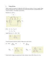
<strong>Chapter</strong> 2: <strong>Semiconductor</strong> <strong>Substrates</strong>Single-crystal l silicon is the enablingmaterial of the Information Age just as steelwas the enabling material of the IndustrialRevolution
Silicon (Si) as a SubstrateSilicon is used almost exclusively in the fabrication of semiconductordevices even though many elements exhibit semiconducting properties.• Silicon is an elemental semiconductor. Elemental semiconductors maybe subjected to a large variety of processing steps withoutdecomposition.• Silicon has a wider energy gap (1.1 eV) than Ge (0.67 eV) and canoperate at higher h temperatures (∼125-175°C).• It is easy to passivate the surfacewith a layer of SiO 2 which protects theunderlying device. Si has a nativeoxide layer of 1.5-2.0 nm that growswhen exposed to air.
Useful lTermsMaterial classifications:Single crystal – atoms occupy specific positions on the latticeAmorphous – atoms have no long range orderPolycrystalline – multiple single crystals randomly orientedThe phase diagram is the map of a material in terms of solid/liquidphases for specific temperatures.Solid Solubility: the maximum concentration of an impurity that canbe dissolved in another material under equilibrium conditions.
Ge-Si phase diagram shows regions of stabilitiesMIXEDS
As-Si phase diagramInterested in the low As concentration region because doping willonly add a small amount of impurity to the Si crystal.
Solid Solubility of several dopants in SiNote: Concentration increases to the left
Crystal: an array of repeated unit cellsMiller Indices– away of identifyingcrystal planes (e.g.cube face, facediagonal, bodydiagonal)
Silicon crystallizes in the diamond structureFCC with 4 additional atomsDark atoms arehighlightingcorners, faces,and just one ofthe additionalatoms
Crystal Defects: any interruption in the periodic latticePoint tdefects• vacancies: lattice sites where atoms are missing• interstitials: i i atom occupies a space between occupied sites or an atom locatedin between atoms (self-interstitial)• substitutional: foreign atoms occupy lattice sites normally occupied by SiLine, dislocation defects• edge dislocation: insertion of an extra line of atoms into a regular crystalcausing crystal to distort• screw dislocation: formed by the motion of one part of a crystal with respect toanotherArea defects: stacking faults - extra plane of atoms; grain boundariesBulk defects – 3D irregularities, precipitates; not suited for fabrication ofdevices
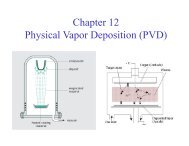
Crystal GrowthSilicon wafer diameter used in manufacturing is300 mm or 12 inchesSingle crystal Si is grown by 2 methods• Czochralski (CZ) process – involves solidification ofa crystal from a melt; electronic grade polysilicon(poly) refined from quartzite (SiO 2 ) until it is verypure as the starting material• Float Zone (FZ) process - a rod of polysiliconattached at one end to an oriented seed crystal ispassed through ha small molten zone initiated i i dby RFheating
CZ MethodFig. 2.12A method forproducing a largeingot (boule) ofsingle crystal Sifrom a seed thatis pulled androtated frommolten Si held ina cruciblelocated in achamber backfilled with inertgas.
Intentional impurities: introduce dopant atoms into the melt sothat t a particular resistivity it wafer can be made.One difficulty encountered is that the concentration of the dopant in thesolid and liquid are different. A segregation coefficient, k, is defined as:k = C s /C lwhere C s and C l are equilibrium impurity concentrations of the solid andliquid, id respectively.Table 2.1: Segregation coefficients for common impurities in SiAl As B O P Sb0.002 0.3 0.8 0.25 0.35 0.023Best dopants tend to have k closer to 1; generally dopants tend to accumulatein the melt as the crystal grows and radial distribution is good because crystalis rotated but axial distribution of dopants (along the boule) will vary.
A picture of a 200 mm Si crystal as they are grown for chip manufacture in 2000.Note that this hugecrystal is hanging on arather thin Si seedcrystal.This seed crystal doesnot only have tosupport the weight ofthe crystal, but also thetorque needed to rotatethe crystal lduring itsgrowth.From the "Smithsonian", Jan2000, Vol. 30, No. 10
GaAs growthIt is difficult to maintainstoichiometry so liquidencapsulated ltdCZ(LEC)andBridgman growth are common
Bridgman: uses a multi-zone furnace to grow GaAs
Float Zone ProcessA method forproducing highpurity Silicon(no crucible)
Wafer PreparationAfter growing the boule, the seed and tail are cut off and the bouleis trimmed to the proper diameter. Either a flat (smaller wafers)or a notch (larger wafers) is ground into the edge of the boule toidentify crystal orientation. A chemical etch is done to removedamage from grinding and then the boule is sliced into waferswith some type of diamond d blade. One or both sides receivemechanical polishing with a chemical slurry.