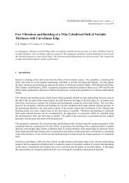
Mechanics of nanoparticle adhesion â A continuum approach
Mechanics of nanoparticle adhesion â A continuum approach
Mechanics of nanoparticle adhesion â A continuum approach

You also want an ePaper? Increase the reach of your titles
YUMPU automatically turns print PDFs into web optimized ePapers that Google loves.
Particles on Surfaces 8: Detection, Adhesion and Removal, pp. 1–47Ed. K.L. Mittal© VSP 2003<strong>Mechanics</strong> <strong>of</strong> <strong>nanoparticle</strong> <strong>adhesion</strong> — A <strong>continuum</strong><strong>approach</strong>JÜRGEN TOMAS ∗Mechanical Process Engineering, Department <strong>of</strong> Process Engineering and Systems Engineering,Otto-von-Guericke-University, Universitätsplatz 2, D-39106 Magdeburg, GermanyAbstract—The fundamentals <strong>of</strong> particle-particle <strong>adhesion</strong> are presented using <strong>continuum</strong> mechanics<strong>approach</strong>es. The models for elastic (Hertz, Huber, Cattaneo, Mindlin and Deresiewicz), elastic<strong>adhesion</strong>(Derjagin, Bradley, Johnson), plastic-<strong>adhesion</strong> (Krupp, Molerus, Johnson, Maugis and Pollock)contact deformation response <strong>of</strong> a single, normal or tangential loaded, isotropic, smooth contact<strong>of</strong> two spheres are discussed. The force-displacement behaviors <strong>of</strong> elastic–plastic (Schubert,Thornton), elastic–dissipative (Sadd), plastic–dissipative (Walton) and viscoplastic–<strong>adhesion</strong>(Rumpf) contacts are also shown. Based on these theories, a general <strong>approach</strong> for the time and deformationrate dependent and combined viscoelastic, plastic, viscoplastic, <strong>adhesion</strong> and dissipativebehaviors <strong>of</strong> a spherical particle contact is derived and explained. The decreasing contact stiffnesswith decreasing particle diameter is the major reason for <strong>adhesion</strong> effects at nanoscale. Using themodel “stiff particles with s<strong>of</strong>t contacts”, the combined influence <strong>of</strong> elastic-plastic and viscoplasticrepulsions in a characteristic (averaged) particle contact is shown. The attractive particle <strong>adhesion</strong>term is described by a sphere–sphere model for van der Waals forces without any contact deformationand a plate–plate model for this micro-contact flattening is presented. Various contact deformationpaths for loading, unloading, reloading and contact detachment are discussed. Thus, the varying<strong>adhesion</strong> forces between particles depend directly on this “frozen” irreversible deformation, the socalledcontact pre-consolidation history. Finally, for colliding particles the correlation between particleimpact velocity and contact deformation response is obtained using energy balance. This constitutivemodel <strong>approach</strong> is generally applicable for solid micro- or nanocontacts but has beenshown here for dry titania <strong>nanoparticle</strong>s.Keywords: Powder; particle mechanics; contact behavior; constitutive models; <strong>adhesion</strong> force;<strong>nanoparticle</strong>s.1. INTRODUCTIONIn terms <strong>of</strong> particle processing and product handling, the well-known flow problems<strong>of</strong> cohesive powders in storage and transportation containers, conveyors orprocess apparatuses include bridging, channeling and oscillating mass flow rates.In addition, flow problems are related to particle characteristics associated with∗ Phone: (49-391) 67-18783, Fax: (49-391) 67-11160,E-mail: juergen.tomas@vst.uni-magdeburg.de
2J. Tomasfeeding and dosing, as well as undesired effects such as widely spread residencetime distribution, time consolidation or caking, chemical conversions and deterioration<strong>of</strong> bioparticles. Finally, insufficient apparatus and system reliability <strong>of</strong>powder processing plants are also related to these flow problems. The rapid increasingproduction <strong>of</strong> cohesive to very cohesive nanopowders, e.g., very adheringpigment particles, micro-carriers in biotechnology or medicine, auxiliary materialsin catalysis, chromatography or silicon wafer polishing, make theseproblems much serious. Taking into account this list <strong>of</strong> technical problems andhazards, it is essential to deal with the fundamentals <strong>of</strong> particle <strong>adhesion</strong>, powderconsolidation and flow, i.e. to develop a reasonable combination <strong>of</strong> particle and<strong>continuum</strong> mechanics.The well-known failure hypotheses <strong>of</strong> Tresca, Coulomb and Mohr and Druckerand Prager (in Refs. [1, 2]), the yield locus concept <strong>of</strong> Jenike [3, 4] and Schwedes[5], the Warren–Spring equations [6–10], and the <strong>approach</strong> by Tüzün [12], etc.,were supplemented by Molerus [13–16] to describe the cohesive, steady-stateflow criterion. Nedderman [17, 18], Jenkins [19] and others discussed the rapidand collisional flow <strong>of</strong> non-adhering particles, as well as Tardos [20] discussedthe frictional flow for compressible powders without any cohesion from the fluidmechanics point <strong>of</strong> view. Additionally, the simulation <strong>of</strong> particle dynamics <strong>of</strong> freeflowing granular media is increasingly used, see, e.g., Cundall [21], Campbell[22], Walton [23, 24], Herrmann [25] and Thornton [26].Additionally, particle <strong>adhesion</strong> effects are related to undesired powder blockingat conveyer transfer chutes or in pneumatic pipe bends [27] in powder handlingand transportation, to desired particle cake formation on filter media [28, 29], towear effects <strong>of</strong> adhering solid surfaces [30, 31], fouling in membrane filtration,fine particle deposition in lungs, formulation <strong>of</strong> particulate products [32–35] or tosurface cleaning <strong>of</strong> silicon wafers [36–40, 133], etc.The force–displacement behaviors <strong>of</strong> elastic, elastic–<strong>adhesion</strong>, plastic–<strong>adhesion</strong>, elastic–plastic, elastic–dissipative, plastic–dissipative and viscoplastic–<strong>adhesion</strong> contacts are shown. Based on these individual theories, a general <strong>approach</strong>for the time and deformation rate dependent and combined viscoelastic,plastic, viscoplastic, <strong>adhesion</strong> and dissipative behaviors <strong>of</strong> a spherical particlecontact is derived and explained.2. PARTICLE CONTACT CONSTITUTIVE MODELSIn terms <strong>of</strong> particle technology, powder processing and handling, Molerus [13,14] explained the consolidation and non-rapid flow <strong>of</strong> dry, fine and cohesivepowders (particle diameter d < 10 µm) in terms <strong>of</strong> the <strong>adhesion</strong> forces at particlecontacts. In principle, there are four essential mechanical deformation effects inparticle–surface contacts and their force–response (stress-strain) behavior can beexplained as follows (Table 1):
<strong>Mechanics</strong> <strong>of</strong> <strong>nanoparticle</strong> <strong>adhesion</strong> — A <strong>continuum</strong> <strong>approach</strong> 3(1) elastic contact deformation (Hertz [41], Huber [42], Derjaguin [43], Bradley[44, 45], Cattaneo [46], Mindlin [47], Sperling [48], Krupp [49], Greenwood[50], Johnson [51], Dahneke [52], Thornton [53, 54], Sadd [55]), which is reversible,independent <strong>of</strong> deformation rate and consolidation time effects andvalid for all particulate solids;(2) plastic contact deformation with <strong>adhesion</strong> (Derjaguin [43], Krupp [56], Schubert[57], Molerus [13, 14], Maugis [58], Walton [59] and Thornton [60]),which is irreversible, deformation rate and consolidation time independent,e.g. mineral powders;(3) viscoelastic contact deformation (Yang [61], Krupp [49], Rumpf et al. [62]and Sadd [55]), which is reversible and dependent on deformation rate andconsolidation time, e.g., bio-particles;(4) viscoplastic contact deformation (Rumpf et al. [62]), which is irreversible anddependent on deformation rate and consolidation time, e.g., <strong>nanoparticle</strong>s fusion.This paper is intended to focus on a characteristic, s<strong>of</strong>t contact <strong>of</strong> two isotropic,stiff, linear elastic, smooth, mono-disperse spherical particles. Thus, this s<strong>of</strong>t orcompliant contact displacement is assumed to be small (h K /d
4J. Tomas
<strong>Mechanics</strong> <strong>of</strong> <strong>nanoparticle</strong> <strong>adhesion</strong> — A <strong>continuum</strong> <strong>approach</strong> 5
6J. Tomas
<strong>Mechanics</strong> <strong>of</strong> <strong>nanoparticle</strong> <strong>adhesion</strong> — A <strong>continuum</strong> <strong>approach</strong> 7
8J. Tomas
<strong>Mechanics</strong> <strong>of</strong> <strong>nanoparticle</strong> <strong>adhesion</strong> — A <strong>continuum</strong> <strong>approach</strong> 9and the median particle radius r 1,2 (characteristic radius <strong>of</strong> contact surface curvature)(Fig. 1),r12 , 1 1 –= +r1 r 2 and the average material stiffness (E, modulus <strong>of</strong> elasticity; ν, Poisson ratio)1(3)*E1−ν1= 2⋅ + E2 21−ν21E2one can calculate the correlation between normal force F N and maximum contactradius r K,el :3⋅r⋅F2⋅E3 12 , N=Kel , *rConsidering surface displacement out <strong>of</strong> the contact zone (for details, seeHuber [42]) the so-called particle center <strong>approach</strong> or height <strong>of</strong> overlap <strong>of</strong> bothparticles h K is [41]:2K K, el 12 ,−1(4)(5)h = r / r(6)Substitution <strong>of</strong> Eq. (6) in Eq. (5) results in a non-linear relation between elasticcontact force and deformation [41] (Fig. 1):2 * 3FN = ⋅E ⋅ r3 12 ,⋅ hK(7)Eq. (7) is shown as the dashed curve marked Hertz. The maximum pressure2p max , Eq. (2), is 1.5 times the average pressure FN/( π ⋅ rK , el)on the contact areaand lies below the micro-yield strength p f . Because <strong>of</strong> surface bending and, consequently,the opportunity for unconfined yield at the surface perimeter outside <strong>of</strong>the contact circle r K ≥ r K,el (Fig. 1b), a maximum tensile stress is found [42]σtmax , ≈− 015 . ⋅pmax(here negative because <strong>of</strong> positive pressures in powder mechanics):2t1−2⋅νrK2max3r ≥r rKel,σpKK,el=− ⋅ (8)This critical stress for cracking <strong>of</strong> a brittle particle material with low tensilestrength is smaller than the maximum shear stress τmax≈ 031 . ⋅ pmaxaccording toEq. (11) which is found at the top <strong>of</strong> a virtual stressing cone below the contact
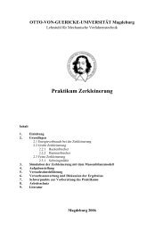
10J. TomasFigure 1. Characteristic spherical particle contact deformation. (a) Approach and (b) elastic contactdeformation (titania, primary particles d = 20–300 nm, surface diameter d S = 200 nm, median particlediameter d 50,3 = 610 nm, specific surface area A S,m = 12 m²/g, solid density ρ s = 3870 kg/m 3 , surfacemoisture X W = 0.4%, temperature θ = 20°C) [148]. Pressure and compression are defined aspositive but tension and extension are negative. The origin <strong>of</strong> this diagram (h K = 0) is equivalent tothe characteristic <strong>adhesion</strong> separation for direct contact (atomic center to center distance), and canbe estimated for a molecular force equilibrium a = a 0 = a F=0 . After <strong>approach</strong>ing from an infinite distance–∞ to this minimum separation a F=0 the sphere–sphere contact without any contact deformationis formed by the attractive <strong>adhesion</strong> force F H0 (the so-called “jump in”). Then the contact maybe loaded F H0 – Y and, as a response, is elastically deformed with an approximate circular contactarea due to the curve marked with Hertz (panel b). The tensile contribution <strong>of</strong> principal stresses accordingto Huber [42] at the perimeter <strong>of</strong> contact circle is neglected for the elliptic pressure distribution,drawn below panel b.
<strong>Mechanics</strong> <strong>of</strong> <strong>nanoparticle</strong> <strong>adhesion</strong> — A <strong>continuum</strong> <strong>approach</strong> 11area on the principal axis r 2 2 2K= x + y = 0 in the depth <strong>of</strong> z ≈ r K,el /2. Combiningthe major principal stress distribution, Eq. (9), σ 1 = σ z (z) at contact radius r K = 0max2rKel2 2+Kel ,σz ( z ) ,=p r zand the minor principal stress, Eq. (10), σ 2 = σ y = σ t (z) [42]KK,el, (9)2t( z) 1rKel, rKel,=− ⋅ +2 2( 1+ ν ) ⋅ 1 z arctanmax2 − ⋅r ≤r rKel,zK,elσp r z , (10)+ the maximum shear stress inside a particle contact r K ≤ r K,el is obtained using theτ = σ − σ [1]:Tresca hypothesis for plastic failure ( )KK,elmax 1 222( z) 3rKel, 1 ν rKel,= ⋅ − + ⋅ 1 z arctan2 2max4 2 − ⋅r ≤r rKel,zK,elτp r z + (11)This internal shear stress distribution becomes more and more critical for ductileor s<strong>of</strong>t solids with a small transition to yield point, and consequently, plasticcontact deformation like <strong>nanoparticle</strong>s with very low stiffness, see Section 2.3.Due to the parabolic curvature F N (h K ), the particle contact becomes stiffer withincreasing diameter r 1,2 , contact radius r K or displacement h K (k N is the contactstiffness in normal direction):dFk = = E ⋅ r ⋅ h = E ⋅ r(12)N * *N dh12 , K KKThe influence <strong>of</strong> a tangential force in a normal loaded spherical contact wasconsidered by Cattaneo [46] and Mindlin [47, 63]. About this and complementarytheories as well as loading, unloading and reloading hysteresis effects, one canfind a detailed discussion by Thornton [53]. He has expressed this tangential contactforce as [53, 54]:( )*4 ψ δ 1 ψ tanϕT 12 , K i NF = ⋅ ⋅G ⋅ r ⋅h ⋅∆ ± − ⋅ ⋅∆ F(13)Here ∆δ is the tangential contact displacement, ψ the loading parameter dependenton loading, unloading and reloading, ϕ i the angle <strong>of</strong> internal friction,G= E 2 1+ ν the shear modulus, and the averaged shear modulus is given as:( )* 2– ν1 2–ν2G = 2⋅ +G1 G 2 – 1(14)
12J. TomasThus, with ψ = 1 the ratio <strong>of</strong> the initial tangential stiffnessdFT*kT= = 4⋅G ⋅ rdδK(15)to the initial normal stiffness according to Eq. (12) is:kkTN( −ν)2⋅1=2 −νHence this ratio ranges from unity, for ν = 0, to 2/3, for ν = 0.5 [63], which isdifferent from the common linear elastic behavior <strong>of</strong> a cylindrical rod.2.1.2. Elastic displacement <strong>of</strong> an <strong>adhesion</strong> contactThe <strong>adhesion</strong> in the normal loaded contact <strong>of</strong> spheres with elastic displacementwill be additionally shown. For fine and stiff particles, the Derjaguin, Muller andToporov (DMT) model [43, 65, 66] predicts that half <strong>of</strong> the interaction forceF H,DMT /2 occurs outside in the annular area which is located at the perimeterclosed by the contact, Eq. (17). This is in contrast to the Johnson, Kendall andRoberts (JKR) model [67], which assumes that all the interactions occur withinthe contact radius <strong>of</strong> the particles. The median <strong>adhesion</strong> force F H,DMT (indexH,DMT) <strong>of</strong> a direct spherical contact can be expressed in terms <strong>of</strong> the work <strong>of</strong><strong>adhesion</strong> W A , conventional surface energy γ A or surface tension σ sls asWA = 2⋅ γA= 2⋅ σsls. The index sls means particle surface-adsorption layers (withliquid equivalent mechanical behavior) – particle surface interaction. If only molecularinteractions with separations near the contact contribute to the <strong>adhesion</strong>force then the so-called Derjaguin approximation [43] is validFHDMT , sls 12 ,(16)= 4⋅π ⋅σ⋅ r , (17)which corresponds to Bradley’s formula [44]. This surface tension σ sls equals halfthe energy needed to separate two flat surfaces from an equilibrium contact distancea F=0 to infinity [75]:σ∞1CHsls,sls=− ⋅ pVdW ( a) da=2 2a24⋅π⋅aF= 0 (18)F = 0The <strong>adhesion</strong> force per unit planar surface area or attractive pressure p VdWwhich is used here to describe the van der Waals interactions at contact is equivalentto a theoretical bond strength and can simply calculated as [75] (e.g., p VdW≈ 3–600 MPa):pC4⋅σHsls ,slsVdW= =36⋅π ⋅aaF = 0 F = 0(19)
<strong>Mechanics</strong> <strong>of</strong> <strong>nanoparticle</strong> <strong>adhesion</strong> — A <strong>continuum</strong> <strong>approach</strong> 13Using this and for a comparison <strong>of</strong> the <strong>adhesion</strong> or bond strength, a dimensionlessratio <strong>of</strong> <strong>adhesion</strong> displacement (extension at contact detachment), expressedas height <strong>of</strong> “neck” h N,T around the contact zone, to minimum molecularcenter separation a F=0 can be defined as2h NT ,4⋅r12 ,⋅σslsΦT = = a2F = 0 * 3E a ⋅F = 0 1/3, (20)which was first introduced by Tabor [74] and later modified and discussed byMuller [66] and Maugis [76]. The DMT model works for very small and stiff particlesΦ T < 0.1 [66, 76, 82]. For separating a stiff, non-deformed spherical pointcontact, the DMT theory [65] predicts a necessary pull-<strong>of</strong>f force F N,Z equivalent tothe <strong>adhesion</strong> reaction force expressed by Eq. (17).Compared with the stronger covalent, ionic, metallic or hydrogen bonds, theseparticle interactions are comparatively weak. From Eq. (18) the surface tension isabout σ sls = 0.25–50 mJ/m 2 or the Hamaker constant according to the Lifshitz <strong>continuum</strong>theory amounts to C H,sls = (0.2–40)⋅10 –20 J [70, 75]. Notice here, the particleinteractions depend greatly on the applied load, which is experimentally confirmedby atomic force microscopy [78, 79, 98].A balance <strong>of</strong> stored elastic energy, mechanical potential energy and surface energydelivers the contact radius <strong>of</strong> the two spheres [51], expressed here with aconstant <strong>adhesion</strong> force F H,JKR from Eq. (23):( 2, , , )3⋅rr F F F F F2⋅E3 12 ,2= ⋅ + + ⋅ ⋅ +K * N HJKR HJKR N HJKR(21)Eq. (21) indicates a contact radius enhancement with increasing work <strong>of</strong> <strong>adhesion</strong>.The contact force-displacement relation is obtained from Eqs. (6) and (21)and can be compared with the Hertz relation Eq. (7) by the curves in Fig. 2marked with Hertz and JKR:**⋅ E34⋅E⋅FH,JKR3N 12 , K 12 , KF = 2 ⋅ r ⋅h − ⋅ r ⋅ h(22)3 3For small contact deformation the so-called JKR limit [51] is half <strong>of</strong> the constant<strong>adhesion</strong> force F H,JKR . This JKR model can be applied for higher bondstrengths Φ T > 5 [76, 82–84]. It is valid for comparatively larger and s<strong>of</strong>ter particlesthan the DMT model predicts [115]:FHJKR,FNZJKR , ,= = 3⋅π ⋅σ2sls⋅ r12,(23)Thus the contact radius for zero load F N = 0,
14J. TomasFigure 2. Characteristic particle contact deformation. (c) Elastic–plastic compression [148]. Thedominant linear elastic–plastic deformation range between pressure levels <strong>of</strong> powder mechanics [4]is demonstrated here. If the maximum pressure in the contact center reaches the micro-yield strengthp max = p f at the yield point Y then the contact starts with plastic yielding which is intensified by mobileadsorption layers. Next, the combined elastic–plastic yield boundary <strong>of</strong> the partial plate–platecontact is achieved as given in Eq. (58). This displacement is expressed with the annular elastic A el(thickness r K,el ) and circular plastic A pl (radius r K,pl ) contact area, shown below panel c.
<strong>Mechanics</strong> <strong>of</strong> <strong>nanoparticle</strong> <strong>adhesion</strong> — A <strong>continuum</strong> <strong>approach</strong> 153 ⋅r3 12 ,⋅FHJKR,K0 , *r = (24)Eis reduced to the pull-<strong>of</strong>f contact radius, i.e.,3K, pull <strong>of</strong>f=K,04r-r / . (25)Additionally, with applying an increasing tangential force F T , the contact radiusr K is reduced by the last term within the square root:r F F F F F2⋅E4⋅G2 *33⋅r12 ,2 FT⋅ EK= ⋅ N+ HJKR ,+ 2⋅ * HJKR ,⋅N+ HJKR ,−*, (26)When the square root in Eq. (26) disappears to zero, a critical value F T,crit is obtained,the so-called “peeling” <strong>of</strong> contact surfaces [64, 88]:F2( 2HJKR , N HJKR , )⋅F ⋅ F + F ⋅G= 2⋅ (27)ETcrit , *An effective or net normal force (F N + F H,JKR ) remains additionally in the contact[54]. Considering F T > F T,crit , i.e., contact failure by sliding (see Mindlin[63]), the tangential force limit is expressed as FT = tanϕi⋅ ( FN + FH0). The <strong>adhesion</strong>force F H0 (index H0) is constant during contact failure and the coefficient(or angle) <strong>of</strong> internal friction µ i= tanϕiis also assumed to be constant for amulti-asperity contact [50, 81, 82]. This constant friction was <strong>of</strong>ten confirmed forrough surfaces in both elastic and plastic regimes [50, 81, 84], but not for a single-asperitycontact with nonlinear dependence <strong>of</strong> friction force on normal load[82, 84].Rearranging Eq. (26), the extended contact force–displacement relation showsa reduction <strong>of</strong> the Hertz (first square-root) and JKR contributions to normal loadF N which is needed to obtain a given displacement h K :**2 *E34⋅E ⋅FHJKR,3 FT⋅ EN= ⋅ ⋅12 ,⋅K− ⋅12 ,⋅K−*F 2 r h r h3 3 4⋅G*(28)However in terms <strong>of</strong> small particles (d < 10 µm), the increase <strong>of</strong> contact areawith elastic deformation does not lead to a significant increase <strong>of</strong> attractive <strong>adhesion</strong>forces because <strong>of</strong> a practically too small magnitude <strong>of</strong> van der Waals energy<strong>of</strong> <strong>adhesion</strong> (Eq. (18)). The reversible elastic repulsion restitutes always the initialcontact configuration during unloading.Consequently, the increase <strong>of</strong> <strong>adhesion</strong> by compression, e.g., forming a snowball, the well-known cohesive consolidation <strong>of</strong> a powder or the particle interac-
16J. Tomastion and remaining strength after tabletting must be influenced by irreversiblecontact deformations, which are shown for a small stress level in a powder bulk inFigs 2 and 3.If the maximum pressure p max = p f in the center <strong>of</strong> the contact circle reaches themicro-yield strength, the contact starts with irreversible plastic yielding (index f).From Eqs. (2) and (5) the transition radius r K,f and from Eq. (6) the center <strong>approach</strong>h K,f are calculated as:hπ ⋅r⋅ p= (29)E12 , fKf , *r2 2π ⋅r12 ,⋅ pfKf ,* 2= (30)EFigure 2 demonstrates the dominant irreversible deformation over a wide range<strong>of</strong> contact forces. This transition point Y for plastic yielding is essentially shiftedtowards smaller normal stresses because <strong>of</strong> particle <strong>adhesion</strong> influence.Rumpf et al. [62] and Molerus [13, 14] introduced this philosophy in powdermechanics and the JKR theory was the basis <strong>of</strong> <strong>adhesion</strong> mechanics [58, 67, 76,85, 86, 90].2.1.3. Perfect plastic and viscoplastic contact displacementActually, assuming perfect contact plasticity, one can neglect the surfacedeformation outside <strong>of</strong> the contact zone and obtain with the following geometricalrelation <strong>of</strong> a sphere( ) 22 2 22K 1 1 K1 , 1 K1 , K1 , 1 K1 ,r = r − r − h = ⋅r ⋅h −h ≈d ⋅ h(31)the total particle center <strong>approach</strong> <strong>of</strong> the two spheres:2 2 2K K Kr r rhK = hK1 ,+ hK,2= + = (32)d d 2 ⋅ r1 2 12 ,Because <strong>of</strong> this, a linear force–displacement relation is found for small sphericalparticle contacts. The repulsive force as a resistance against plastic deformationis given as:F = p ⋅ A = π ⋅d ⋅ p ⋅ h(33)Npl , f K 12 , f KThus, the contact stiffness is constant for perfect plastic yielding behavior, butdecreases with smaller particle diameter d 1,2 especially for cohesive fine powdersand <strong>nanoparticle</strong>s:dFk = = ⋅d ⋅ p(34)NπNpl , dh12 , fK
<strong>Mechanics</strong> <strong>of</strong> <strong>nanoparticle</strong> <strong>adhesion</strong> — A <strong>continuum</strong> <strong>approach</strong> 17Figure 3. Characteristic particle contact deformation. (d) Elastic unloading and reloading with dissipation(titania) [148]. After unloading U – E the contact recovers elastically in the compressionmode and remains with a perfect plastic displacement h K,E . Below point E on the axis the tensionmode begins. Between the points U – E – A the contact recovers elastically according to Eq. (64) toa displacement h K,A . The reloading curve runs from point A to U to the displacement h K,U , Eq. (65).
18J. TomasAdditionally, the rate-dependent, perfect viscoplastic deformation (at the point<strong>of</strong> yielding) expressed by contact viscosity η K times indentation rate h Kis assumedto be equivalent to yield strength p f multiplied by indentation height incrementh Kp ⋅ h = η ⋅h (35)f K K Kand one obtains again a linear model regarding strain rate:F = η ⋅ A = π ⋅d ⋅η⋅h(36)Nvis , K K 12 , K KAn attractive viscous force is observed, e.g., for capillary numbersCa = η ⋅ h / σ > 1 when comparatively strong bonds <strong>of</strong> (low-viscous) liquidK K lgbridges are extended with negative velocity –h [71–73].KConsequently, the particle material parameters: contact micro-yield strength p fand viscosity η K are measures <strong>of</strong> irreversible particle contact stiffness or s<strong>of</strong>tness.Both plastic and viscous contact yield effects were intensified by mobile adsorptionlayers on the surfaces. The sum <strong>of</strong> deformation increments results in the energydissipation. For larger particle contact areas A K , the conventional linear elasticand constant plastic behavior is expected.Now, what are the consequences <strong>of</strong> small contact flattening with respect to avarying, i.e., load or pre-history-dependent <strong>adhesion</strong>?2.2. Particle contact consolidation by varying <strong>adhesion</strong> forceKrupp [49] and Sperling [48, 56] developed a model for the increase <strong>of</strong> <strong>adhesion</strong>force F H (index H) <strong>of</strong> the contact. This considerable effect is called here as “consolidation”and is expressed as the sum <strong>of</strong> <strong>adhesion</strong> force F H0 according to Eq.(17) plus an attractive/repulsive force contribution due to irreversible plastic flattening<strong>of</strong> the spheres (p f is the repulsive “microhardness” or micro-yield strength<strong>of</strong> the s<strong>of</strong>ter contact material <strong>of</strong> the two particles, σ ss /a 0 is the attractive contactpressure, index ss represents solid–vacuum–solid interaction): 2⋅σFH = 4⋅π⋅r 12 ,⋅σss⋅ 1+ a ⋅ pss0 f(37)Dahneke [52] modified this <strong>adhesion</strong> model by the van der Waals force withoutany contact deformation F H0 plus an attractive van der Waals pressure (force perunit surface) p VdW contribution due to partially increasing flattening <strong>of</strong> the sphereswhich form a circular contact area A K (C H is the Hamaker constant based on interactingmolecule pair additivity [69, 75]):
<strong>Mechanics</strong> <strong>of</strong> <strong>nanoparticle</strong> <strong>adhesion</strong> — A <strong>continuum</strong> <strong>approach</strong> 19H 12 ,KH=H0+K⋅ VdW= ⋅ 12 +6 a a00F F A pC ⋅r 2⋅h ⋅ (38)The distance a 0 denotes a characteristic <strong>adhesion</strong> separation. If stiff molecularinteractions are provided (no compression <strong>of</strong> electron sheath), this separation a 0was assumed to be constant during contact loading. By addition the elastic repulsion<strong>of</strong> the solid material according to Hertz, Eq. (7), to this attraction force, Eq.(38), and by deriving the total force F tot with respect to h K , the maximum <strong>adhesion</strong>force was obtained as absolute valueF2CH⋅r12 ,2⋅CH⋅r12,Hmax ,= ⋅ 1+2 26⋅ a * 70 27⋅E ⋅a0which occurs at the center <strong>approach</strong> <strong>of</strong> the spheres [52]:h2CH⋅r12,Kmax ,=* 2 69⋅E⋅a0, (39)(40)But as mentioned before, this increase <strong>of</strong> contact area with elastic deformationdoes not lead to a significant increase <strong>of</strong> attractive <strong>adhesion</strong> force. The reversibleelastic repulsion restitutes always the initial contact configuration. The practicalexperience with the mechanical behavior <strong>of</strong> fine powders shows that an increase<strong>of</strong> <strong>adhesion</strong> force is influenced by an irreversible or “frozen” contact flatteningwhich depends on the external force F N [57].Generally, if this external compressive normal force F N is acting at a single s<strong>of</strong>tcontact <strong>of</strong> two isotropic, stiff, smooth, mono-disperse spheres the previous contactpoint is deformed to a contact area, Fig. 1a to Fig. 2c, and the <strong>adhesion</strong> force betweenthese two partners increases, see in Fig. 3 the so-called “<strong>adhesion</strong> boundary”for incipient contact detachment. During this surface stressing the rigid particleis not so much deformed that it undergoes a certain change <strong>of</strong> the particleshape. In contrast, s<strong>of</strong>t particle matter such as biological cells or macromolecularorganic material do not behave so.For s<strong>of</strong>t contacts Rumpf et al. [62] have developed a constitutive model <strong>approach</strong>to describe the linear increase <strong>of</strong> <strong>adhesion</strong> force F H , mainly for plastic contactdeformation:( ) pVdW pVdWFH = 1+ ⋅ FH0 + ⋅ FN = 1+ κp ⋅ FH0 + κp⋅F(41)N pf pfWith analogous prerequisites and derivation, Molerus [14] obtained an equivalentexpression:
20J. TomaspF = F + ⋅ F = F + ⋅ F(42)VdWκH H0 p N H0 p NfThe <strong>adhesion</strong> force F H0 without additional consolidation (F N = 0) can be <strong>approach</strong>edas a single rigid sphere–sphere contact (Fig. 1a). But, if this particlecontact is s<strong>of</strong>t enough the contact is flattened by an external normal force F N to aplate–plate contact (Fig. 2c). The coefficient κ p describes a dimensionless ratio <strong>of</strong>attractive van der Waals pressure p VdW for a plate–plate model, Eq. (19), to repulsiveparticle micro-hardness p f which is temperature sensitive:p Cκ (43)VdWH,slsp= =p 3f 6 ⋅ π ⋅ aF= 0 ⋅ pfThis is referred to here as a plastic repulsion coefficient. The Hamaker constantC H,sls for solid–liquid–solid interaction (index sls) according to Lifshitz’ theory[70] is related to continuous media which depends on their permittivities (dielectricconstants) and refractive indices [75]. The characteristic <strong>adhesion</strong> separationfor a direct contact is <strong>of</strong> a molecular scale (atomic center-to-center distance) andcan be estimated for a molecular force equilibrium (a = a F=0 ) or interaction potentialminimum [75, 76, 91]. Its magnitude is about a F=0 ≈ 0.3–0.4 nm. This separationdepends mainly on the properties <strong>of</strong> liquid-equivalent packed adsorbed waterlayers. This particle contact behavior is influenced by mobile adsorption layersdue to molecular rearrangement. The minimum separation a F=0 is assumed to beconstant during loading and unloading for technologically relevant powder pressuresσ < 100 kPa (Fig. 2c).For a very hard contact this plastic repulsion coefficient is infinitely small, i.e.,κ p ≈ 0, and for a s<strong>of</strong>t contact κ p → 1.If the contact circle radius r K is small compared to the particle diameter d, theelastic and plastic contact displacements can be combined and expressed with theannular elastic A el and circular plastic A pl contact area ratio [57]:pF F FVdWH=H0+ ⋅N2 A elpf⋅ 1+ ⋅ 3 Apl(44)For a perfect plastic contact displacement A el → 0 and one obtains again Eq.(42):F ≈ F + κ ⋅ F(45)H H0 p NThis linear enhancement <strong>of</strong> <strong>adhesion</strong> force F H with increasing preconsolidationforce F N , Eqs. (41), (42) and (45), was experimentally confirmedfor micrometer sized particles, e.g., by Schütz [94, 95] (κ p = 0.3 for limestone)and Newton [96] (κ p = 0.333 for poly(ethylene glycol), κ p = 0.076 for starch, κ p =
<strong>Mechanics</strong> <strong>of</strong> <strong>nanoparticle</strong> <strong>adhesion</strong> — A <strong>continuum</strong> <strong>approach</strong> 210.017 for lactose, κ p = 0.016 for CaCO 3 ) with centrifuge tests [92] as well as bySingh et al. [97] (κ p = 0.12 for poly(methylmethacrylate), κ p ≈ 0 for very hardsapphire, α-Al 2 O 3 ) with an Atomic Force Microscope (AFM). The two methodsare compared with rigid and rough glass spheres (d = 0.1–10 µm), without anycontact deformation, by H<strong>of</strong>fmann et al. [98]. Additionally, using the isostatictensile strength σ 0 determined by powder shear tests [91, 122, 147, 149, 151], this<strong>adhesion</strong> level is <strong>of</strong> the same order <strong>of</strong> magnitude as the average <strong>of</strong> centrifuge tests(see Spindler et al. [99]).The enhancement <strong>of</strong> <strong>adhesion</strong> force F H due to pre-consolidation was confirmedby Tabor [30], Maugis [85, 86] and Visser [110]. Also, Maugis and Pollock [58]found that separation was always brittle (index br) with a small initial slope <strong>of</strong>pull-<strong>of</strong>f force, dF N,Z,br /dF N (F N,Z,br ≈ – F H ), for a comparatively small surface energyσ ss <strong>of</strong> the rigid sphere–gold plate contact (index ss). In contrast, a pull-<strong>of</strong>fforce F N,Z,br proportional to FNwas obtained from the JKR theory [58] for thefull plastic range <strong>of</strong> high loading and brittle separation <strong>of</strong> the contact (Table 1):FF* NN,Z,br=−σss⋅E⋅3π ⋅ pf(46)Additionally, a load-dependent <strong>adhesion</strong> force was also experimentally confirmedin wet environment <strong>of</strong> the particle contact by Butt and co-workers [78, 79]and Higashitani and co-workers [87] with AFM measurements.The dominant plastic contact deformation <strong>of</strong> surface asperities during thechemical–mechanical polishing process <strong>of</strong> silicon wafers was also recognized,e.g., by Rimai and Busnaina [111] and Ahmadi and Xia [141]. These particlesurfacecontacts and, consequently, asperity stressing by simultaneous normalpressure and shearing, contact deformation, microcrack initiation and propagation,and micr<strong>of</strong>racture <strong>of</strong> brittle silicon asperity peaks affect directly the polishingperformance. Thus the Coulomb friction becomes dominant also in a wet environment.2.3. Variation in <strong>adhesion</strong> due to non-elastic contact consolidation2.3.1. Elastic–plastic force–displacement modelAll interparticle forces can be expressed in terms <strong>of</strong> a single potential functionFi =±∂Ui( hi)/∂hiand thus are superposed. This is valid only for a conservativesystem in which the work done by the force F i versus distance h i is not dissipatedas heat, but remains in the form <strong>of</strong> mechanical energy, simply in terms <strong>of</strong> irreversibledeformation, e.g., initiation <strong>of</strong> nanoscale distortions, dislocations or latticestacking faults. The overall potential function may be written as the sum <strong>of</strong>the potential energies <strong>of</strong> a single contact i and all particle pairs j. Minimizing thispotential function ∂U / ∂ h = 0 one obtains the potential-force balance.ij ijij
22J. TomasThus, the elastic–plastic force–displacement models introduced by Schubert etal. [57], Eq. (44), and Thornton [60] Eq. (47)( )F N =π⋅p f ⋅r 1,2 ⋅ h K −hK,f / 3(47)should be supplemented here with a complete attractive force contribution due tocontact flattening described before. Taking into account Eqs. (41), (42) and (44),the particle contact force equilibrium between attraction (-) and elastic plus, simultaneously,plastic repulsion (+) is given by ( r * Krepresents the coordinate <strong>of</strong>annular elastic contact area):2 2H0 VdWπK N fπK,plF = 0 =−F − p ⋅ ⋅r − F + p ⋅ ⋅rrKK,pl* * *el K K K+ 2 ⋅π⋅ p ( r ) ⋅r drr3/2(48)222 2 2⋅π⋅ pmax ⋅r rK K,pl FN + F H0+ pVdW ⋅π ⋅ rK = pf ⋅π ⋅ rK,pl+ ⋅ 1− 3 (49)r K At the yield point r K = r K,pl the maximum contact pressure reaches the yieldstrength p el = p f .222 2 2⋅π⋅rK pf FN + F H0+ pVdW ⋅π ⋅ rK = pf ⋅ π ⋅ rK,pl+ ⋅3 (50) pmax Because <strong>of</strong> plastic yielding, a pressure higher than p f is absolutely not possibleand thus, the fictitious contact pressure p max is eliminated by Eq. (1):2 22 2 2⋅π⋅r r K K,plFN + FH0 + p VdW⋅π ⋅ rK = pf ⋅ π ⋅ rK,pl + ⋅ 1−(51)32 r K Finally, the contact force equilibrium2r2K,pl+ + ⋅ = π ⋅ ⋅ ⋅ 2+ 1⋅N H0 VdW K f K 3 3 2 rKF F p A p rand the total contact area A K are obtained: A= p ⋅A⋅ 2+ 1⋅f K 3 3 AplK(52)
<strong>Mechanics</strong> <strong>of</strong> <strong>nanoparticle</strong> <strong>adhesion</strong> — A <strong>continuum</strong> <strong>approach</strong> 23AK=FN+ FH0 A2 1 pl pf⋅ + ⋅ −3 3pAK VdW(53)Next, the elastic–plastic contact area coefficient κ A is introduced. This dimensionlesscoefficient represents the ratio <strong>of</strong> plastic particle contact deformation areaA pl to total contact deformation area AK = Apl + A and includes a certain elasticeldisplacement:κ 2 1 plA= + ⋅ A 3 3 A(54)The solely elastic contact deformation A pl = 0, κ A = 2/3, has only minor relevancefor cohesive powders in loading (Fig. 2), but for the complete plastic contactdeformation (A pl = A K ) the coefficient κ A = 1 is obtained.From Eqs. (43), (53) and (54) the sum <strong>of</strong> contact normal forces is obtained as:K( )2N+H0= ⋅K⋅ f⋅A−pF F π r p κ κ (55)From Eq. (5) the transition radius <strong>of</strong> elastic-plastic model r K,f,el-pl (index el-pl)and from Eq. (6) the particle center <strong>approach</strong> <strong>of</strong> the two particles h K,f,el-pl are calculatedas:h( )3⋅π ⋅r⋅ p ⋅ κ −κ1,2 f A p=K,f,el−pl *r2⋅E( ) 22 29⋅π ⋅r⋅ p ⋅ κ −κ1,2 f A pK,f,el−=pl* 24⋅E(56)(57)Checking this model, Eq. (56), with pure elastic contact deformation, i.e., κ p →0 and κ A = 2/3, the elastic transition radius r K,f , Eq. (29), is also obtained. For example,nanodisperse titania particles (d 50,3 = 610 nm is the median diameter onmass basis (index 3), E = 50 kN/mm 2 modulus <strong>of</strong> elasticity, ν = 0.28 Poisson ratio,p f = 400 N/mm 2 micro-yield strength, κ A ≈ 5/6 contact area ratio, κ p = 0.44plastic repulsion coefficient) a contact radius <strong>of</strong> r K,f,el-pl = 2.1 nm and, from Eq.(57), a homeopathic center <strong>approach</strong> <strong>of</strong> only h K,f,el-pl = 0.03 nm are obtained. Thisis a very small indentation calculated, in principle, by means <strong>of</strong> a <strong>continuum</strong> <strong>approach</strong>.The contact deformation is equivalent to a microscopic force F N = 2.1 nNor to a small macroscopic pressure level <strong>of</strong> about σ = 1.4 kPa (porosity ε = 0.8) inpowder handling and processing.
24J. TomasIntroducing the particle center <strong>approach</strong> <strong>of</strong> the two particles Eq. (6) in Eq. (55),a very useful linear force–displacement model <strong>approach</strong> is obtained again for κ A ≈constant:( )F + F = π ⋅r ⋅ p ⋅ κ −κ ⋅h(58)N H0 1,2 f A p KBut if one considers the contact area ratio <strong>of</strong> Eq. (63), a slightly nonlinear (progressivelyincreasing) curve is obtained. Using the elastic–plastic contact consolidationcoefficient κ due to definition (Eq. (71)) one can also write:π ⋅r⋅ p ⋅κF F h1+κ1,2 f AN+H0= ⋅KThe curve <strong>of</strong> this model is shown in Fig. 2 for titania powder which wasrecalculated from material data and shear test data [147, 149]. The slope <strong>of</strong> thisplastic curve is a measure <strong>of</strong> irreversible particle contact stiffness or s<strong>of</strong>tness, Eq.(34). Because <strong>of</strong> particle <strong>adhesion</strong> impact, the transition point for plastic yieldingY is shifted to the left compared with the rough calculation <strong>of</strong> the displacementlimit h K,f by Eq. (30).The previous contact model may be supplemented by viscoplastic stress-strainbehavior, i.e., strain-rate dependence on initial yield stress. For elastic–viscoplasticcontact, one obtains deformation with Eqs. (36) and (58) (κ A ≈ constant):F + F = π ⋅r ⋅η ⋅ κ −κ ⋅h(60)( )N H0 1,2 K A p,t K(59)A dimensionless viscoplastic contact repulsion coefficient κ p,t is introduced asthe ratio <strong>of</strong> the van der Waals attraction to viscoplastic repulsion effects which areadditionally acting in the contact after attaining the maximum pressure for yielding.κp,tp=η ⋅hKVdWThe consequences for the variation in <strong>adhesion</strong> force are discussed in Section2.3.3 [147].2.3.2. Unloading and reloading hysteresis and contact detachmentBetween the points U – E (see Fig. 3), the contact recovers elastically along anextended Hertzian parabolic curve, Eq. (7), down to the perfect plastic displacement,h K,E , obtained in combination with Eq. (58):K32= − ⋅K,E K,U K,f K,U(61)h h h h (62)
<strong>Mechanics</strong> <strong>of</strong> <strong>nanoparticle</strong> <strong>adhesion</strong> — A <strong>continuum</strong> <strong>approach</strong> 25Thus, the contact area ratio κ A is expressed more in detail with Eqs. (6) and(54) for elastic κ A = 2/3 and perfect plastic contact deformation, κ A = 1 ifh K,U → ∞:hhκ K,EK,f= 2+ = 1−1⋅3A 3 3⋅hK,U3 h(63)K,UBeyond point E to point A, the same curve runs down to the intersection withthe <strong>adhesion</strong> boundary, Eq. (67), to the displacement h K,A :( ) 3*FN,unload = 2 ⋅E ⋅ r3 1,2⋅ hK −hK,A −F H,A(64)Consequently, the reloading runs along the symmetric curve( ) 3*FN,reload =− 2 ⋅E ⋅ r3 1,2⋅ hK,U − hK + FN,U(65)from point A to point U to the displacement h K,U as well (Fig. 3). The displacementh K,A at point A <strong>of</strong> contact detachment is calculated from Eqs. (57), (58), (64)and (67) as an implied function (index (0) for the beginning <strong>of</strong> iterations) <strong>of</strong> thedisplacement history point h K,U :( κ ) 2h 3K,A,(1)= hK,U − hK,f,el- pl⋅ hK,U + ⋅hK,A,(0)(66)If one replaces F N in Eq. (72) (see Section 2.3.4), by the normal force–displacement relation, Eq. (58), additionally one obtains a plausible <strong>adhesion</strong>force–displacement relation which shows the increased pull-<strong>of</strong>f force level aftercontact flattening, h K = h K,A compared with Eq. (38) and point A in the diagram <strong>of</strong>Fig. 4:F = F + π ⋅r ⋅ p ⋅h(67)H,A H0 1,2 VdW K,AThe unloading and reloading hysteresis for an <strong>adhesion</strong> contact takes place betweenthe two characteristic straight-lines for compression, the elastic–plasticyield boundary Eq. (58), and for tension, the remaining <strong>adhesion</strong> (pull-<strong>of</strong>f)boundary Eq. (67) and Fig. 3.At this so-called <strong>adhesion</strong> (failure) boundary the contact microplates fail anddetach with the increasing distance a= aF= 0+ hK,A −h . The actual particle separationa can be used by a long-range hyperbolic <strong>adhesion</strong> force curve F ∝ aK−3N,Zwith the van der Waals pressure p VdW as given in Eq. (19) and the displacementh K,A for incipient contact detachment by Eq. (66):
26J. TomasFigure 4. Characteristic particle contact deformation. (e) Contact detachment [148]. Again, if oneapplies a certain pull-<strong>of</strong>f force F N,Z = –F H,A as given in Eq. (67) but here negative, the <strong>adhesion</strong>boundary line at failure point A is reached and the contact plates fail and detach with the increasingdistance a= aF = 0+ hK,A−h K. This actual particle separation is considered for the calculation by a3hyperbolic <strong>adhesion</strong> force curve F N,Z = –F ∝ a − <strong>of</strong> the plate–plate model Eq. (68).HA ,
<strong>Mechanics</strong> <strong>of</strong> <strong>nanoparticle</strong> <strong>adhesion</strong> — A <strong>continuum</strong> <strong>approach</strong> 27Figure 5. Characteristic particle contact deformation. The complete survey <strong>of</strong> loading, unloading,reloading, dissipation and detachment behaviors <strong>of</strong> titania [148]. This hysteresis behavior could beshifted along the elastic–plastic boundary and depends on the pre-loading, or in other words, preconsolidationlevel. Thus, the variation in <strong>adhesion</strong> forces between particles depends directly on thisfrozen irreversible deformation, the so-called contact pre-consolidation history.FF + π ⋅r ⋅p ⋅hH0 1,2 VdW K,AN,Z( hK ) =−3 hK,Ah 1K + −aF= 0aF=0(68)These generalized functions in Fig. 3 for the combination <strong>of</strong> elastic-plastic, <strong>adhesion</strong>and dissipative force–displacement behaviors <strong>of</strong> a spherical particle contactwere derived on the basis <strong>of</strong> the theories <strong>of</strong> Krupp [49], Molerus [13], Maugis
28J. Tomas[58], Sadd [55] and, especially, Thornton [53, 60]. A complete survey <strong>of</strong> loading,unloading, reloading, dissipation and detachment behaviors <strong>of</strong> titania is shown inFig. 5 as a combination <strong>of</strong> Fig. 1a to Fig. 4e. This <strong>approach</strong> may be expressedhere in terms <strong>of</strong> engineering mechanics <strong>of</strong> macroscopic continua [1, 2] as the history-dependentcontact behavior.2.3.3. Viscoplastic contact behavior and time dependent consolidationAn elastic-plastic contact may be additionally deformed during the indentationtime, e.g., by viscoplastic flow (Section 2.1.3). Thus, the <strong>adhesion</strong> force increaseswith interaction time [32, 49, 77, 128]. This time-dependent consolidation behavior(index t) <strong>of</strong> particle contacts in a powder bulk was previously described by aparallel series (summation) <strong>of</strong> <strong>adhesion</strong> forces, see Table 1, last line marked withTomas [122–125, 146–149]. This method refers more to incipient sintering orcontact fusion <strong>of</strong> a thermally-sensitive particle material [62] without interstitialadsorption layers. This micro-process is very temperature sensitive [122, 124,125, 146].Additionally, the increasing <strong>adhesion</strong> may be considered in terms <strong>of</strong> a sequence<strong>of</strong> rheological models as the sum <strong>of</strong> resistances due to plastic and viscoplastic repulsionκ p + κ p,t , line 5 in Table 2. Hence the repulsion effect <strong>of</strong> “cold” viscousflow <strong>of</strong> comparatively strongly-bonded adsorption layers on the particle surface istaken into consideration. This rheological model is valid only for a short-term in-Table 2.Material parameters for characteristic <strong>adhesion</strong> force functions F H (F N ) in Fig. 8Constitutive model <strong>of</strong> contactdeformationRepulsion coefficientConstitutive models <strong>of</strong>combined contact deformationContact area ratioContact consolidationcoefficientIntersection with F N -axis(abscissa)Instantaneous contactconsolidationplasticκpCVdWHsls ,p= p =3f 6 ⋅ π ⋅ a F = 0 ⋅ p felastic–plastic2AplTime-dependent consolidationviscoplasticκpt ,pVdW= ⋅ tηKelastic–plastic and viscoplasticκA= + κ3At ,= +3 ⋅ ( Apl+ A3el )3 ⋅ ( Apl + Avis + Ael)κpκ =κ −κApF a h pNZ ,≈−π ⋅F=0 ⋅r⋅12 , f≠ f( CHsls, )κFvis2Aplκp+ κp,t=κ −κ −κNZtot , ,+ AAt , p pt ,( CHsls, )visπ ⋅a ⋅h ⋅ p≈−1+ p ⋅t / η≠ fF=0 r12, ffK
<strong>Mechanics</strong> <strong>of</strong> <strong>nanoparticle</strong> <strong>adhesion</strong> — A <strong>continuum</strong> <strong>approach</strong> 29Figure 6. Characteristic elastic–plastic, viscoelastic–viscoplastic particle contact deformations (titania,primary particles d = 20–300 nm, surface diameter d S = 200 nm, median particle diameterd 50,3 = 610 nm, specific surface area A S,m = 12 m 2 /g, solid density ρ s = 3870 kg/m 3 , surface moistureX W = 0.4%, temperature θ = 20°C, loading time t = 24 h). The material data, modulus <strong>of</strong> elasticityE = 50 kN/mm 2 , modulus <strong>of</strong> relaxation E ∞ = 25 kN/mm 2 , relaxation time t relax = 24 h, plastic microyieldstrength p f = 400 N/mm 2 , contact viscosity η K = 1.8·10 14 Pa·s, Poisson ratio ν = 0.28, Hamakerconstant C H,sls = 12.6·10 -20 J, equilibrium separation for dipole interaction a F=0 = 0.336 nm, contactarea ratio κ A = 5/6 are assumed as appropriate for the characteristic contact properties. The plasticrepulsion coefficient κ p = 0.44 and viscoplastic repulsion coefficient κ p,t = 0.09 are recalculatedfrom shear-test data in a powder <strong>continuum</strong> [147, 149].
30J. TomasFigure 7. Constitutive models <strong>of</strong> contact deformation <strong>of</strong> smooth spherical particles in normal directionwithout (only compression +) and with <strong>adhesion</strong> (tension –). The basic models for elastic behaviorwere derived by Hertz [41], for constant <strong>adhesion</strong> by Yang [61], for constant <strong>adhesion</strong> byJohnson et al. [51], for plastic behavior by Thornton and Ning [60] and Walton and Braun [59], andfor plasticity with variation in <strong>adhesion</strong> by Molerus [13] and Schubert et al. [57]. This has been expandedstepwise to include nonlinear plastic contact hardening and s<strong>of</strong>tening equivalent to shearthickeningand shear-thinning in suspension rheology [91]. Energy dissipation was considered bySadd et al. [55] and time-dependent viscoplasticity by Rumpf et al. [62]. Considering all these theories,one obtains a general contact model for time- and rate-dependent viscoelastic, plastic, viscoplastic,<strong>adhesion</strong> and dissipative behaviors [91, 146–148, 151].
dentation t < / ( ⋅p)<strong>Mechanics</strong> <strong>of</strong> <strong>nanoparticle</strong> <strong>adhesion</strong> — A <strong>continuum</strong> <strong>approach</strong> 31η κ , e.g., t < 5 d for the titania used as a very cohesiveKfpowder (specific surface area A S,m = 12 m 2 /g, with a certain water adsorption capacity).All the material parameters are collected in Table 2.A viscoelastic relaxation in the particle contact may be added as a timedependentfunction <strong>of</strong> the average modulus <strong>of</strong> elasticity E * , Yang [61] and Krupp[49] (t relax is the characteristic relaxation time):1 = 1 + 1 − 1 ⋅exp−* * * *E E ( ) ( 0) ∞t →∞ E0t = E∞( tt )The slopes <strong>of</strong> the elastic–plastic, viscoelastic–viscoplastic yield and <strong>adhesion</strong>boundaries as well as the unloading and reloading curves, which include a certainrelaxation effect, are influenced by the increasing s<strong>of</strong>tness or compliance <strong>of</strong> thespherical particle contact with loading time (Fig. 6). This model system includesall the essential constitutive functions <strong>of</strong> the authors named before [41, 55, 57, 60,61]. A survey <strong>of</strong> the essential contact force-displacement models is given in Fig. 7and Table 1.Obviously, contact deformation and <strong>adhesion</strong> forces are stochastically distributedmaterial functions. Usually one may focus here only on the characteristic oraveraged values <strong>of</strong> these constitutive functions.2.3.4. Adhesion force modelStarting with all these force-displacement functions one turns to an <strong>adhesion</strong> andnormal force correlation to find out the physical basis <strong>of</strong> strength-stress relationsin <strong>continuum</strong> mechanics [13, 14, 122, 149]. Replacing the contact area in Eq.(38), the following force–force relation is directly obtained:relaxp F + FVdW H0 NFH = FH0 + pVdW⋅ AK = FH0+ ⋅p2 1A pAf pl VdW+ ⋅ −3 3 AKpfp(69)(70)Therefore, with a so-called elastic–plastic contact consolidation coefficient κ,κpκ =(71)κ −κa linear model for the <strong>adhesion</strong> force F H as function <strong>of</strong> normal force F N is obtained(Fig. 8):F κF κF F F( 1 κ )ApH= ⋅H0+ ⋅N= + ⋅H0+ κ ⋅κ NA−κp κA −κp(72)The dimensionless strain characteristic κ is given by the slope <strong>of</strong> <strong>adhesion</strong>force F H which is influenced by predominant plastic contact failure. It is a meas-
32J. TomasFigure 8. Particle contact forces for titania powder (median particle diameter d 50,3 = 610 nm, specificsurface area A S,m = 12 m 2 /g, surface moisture X W = 0.4%, temperature = 20°C) according to thelinear model Eq. (72), non-linear model Eq. (79) for instantaneous consolidation t = 0 and the linearmodel for time consolidation t = 24 h (Eq. (73)). The powder surface moisture X W = 0.4% is accuratelyanalyzed with Karl–Fischer titration. This is equivalent to an idealized mono-molecular adsorptionlayer being in equilibrium with an ambient air temperature <strong>of</strong> 20°C and 50% humidity.ure <strong>of</strong> irreversible particle contact stiffness or s<strong>of</strong>tness. A shallow slope designatesa low <strong>adhesion</strong> level F H ≈ F H0 because <strong>of</strong> stiff particle contacts, but a largeslope means s<strong>of</strong>t contacts, or consequently, a cohesive powder flow behavior [91,147, 149]. The contact flattening may be additionally dependent on time or displacementrate (Section 2.1.3). Thus, the contact reacts s<strong>of</strong>ter and, consequently,the <strong>adhesion</strong> level is higher than before. This new <strong>adhesion</strong> force slope κ vis ismodified by the viscoplastic contact repulsion coefficient κ p,t , which includes certainviscoplastic micr<strong>of</strong>low at the contact (Table 2 and Fig. 8),κκ + κF = ⋅ F + ⋅FAt ,p p,tHtot ,κ −κ −κ H0κ −κ −κNAt , p pt , At , p pt ,( 1 κ )= + ⋅ F + κ ⋅Fvis H0 vis N(73)with the so-called total viscoplastic contact consolidation coefficient κ vis that includesthe elastic-plastic κ p and the viscoplastic contributions κ p,t <strong>of</strong> contact flattening,
<strong>Mechanics</strong> <strong>of</strong> <strong>nanoparticle</strong> <strong>adhesion</strong> — A <strong>continuum</strong> <strong>approach</strong> 33κvisκp+ κp,t=κ −κ −κA,t p p,t(74)F=0 r 1,2Eqs. (72) and (73) consider also the flattening response <strong>of</strong> s<strong>of</strong>t particle contactsat normal force F N = 0 caused by the <strong>adhesion</strong> force κ⋅F H0 (Krupp [56]) andκ vis ⋅F H0 . Hence, the <strong>adhesion</strong> force F H0 represents the sphere–sphere contact withoutany contact deformation at minimum particle–surface separation a F=0 . Thisinitial <strong>adhesion</strong> force F H0 may also include a characteristic nanometer-sizedheight or radius <strong>of</strong> a rigid spherical asperity a < h > a F=0 ), the contribution <strong>of</strong> the plate,second term in Eq. (76), can be neglected and the <strong>adhesion</strong> force may be describedas the sphere-sphere contact [98].Rabinovich and co-workers [113–115] have used the root mean square (RMS)roughness from AFM measurements and the average peak-to-peak distance betweenthese asperities λ r to calculate the interaction between a smooth sphere anda surface with nanoscale roughness pr<strong>of</strong>ile (index Ra):
34J. TomasFC⋅r1 1H,sls 1,2H0,Ra= ⋅ +2 2 26⋅ a F= 01+ 58.14⋅r1,2⋅ RMS / λr ( 1+ 1.817⋅RMS / aF= 0 )(77)The first term in brackets represents the contact interaction <strong>of</strong> the particle withan asperity and the second term accounts for the non-contact interaction <strong>of</strong> theparticle with an average surface plane. This <strong>approach</strong> describes stiff nanoscaleroughness as caps <strong>of</strong> asperities with their centers located far below the surface.For example, RMS roughness <strong>of</strong> only 1 or 2 nm is significant enough to reducethe theoretical <strong>adhesion</strong> force F H0 by an order <strong>of</strong> magnitude or more [115].Greenwood [50, 80, 81] and Johnson [67] described the elastic and plastic deformations<strong>of</strong> random surface asperities <strong>of</strong> contacts by the standard deviation <strong>of</strong>roughness and mean pressure.The intersection <strong>of</strong> function (72) with abscissa (F H = 0) in the negative <strong>of</strong> consolidationforce F N (Fig. 8), is surprisingly independent <strong>of</strong> the Hamaker constantC H,sls :F =−π⋅a ⋅h ⋅p⋅κ⋅ 1+NZ , F=0 r12f A ,≈−π⋅a ⋅h ⋅pF=0 r12, fr/ h12 , r12 ,( 1+ 2⋅h/ ar )12 , F=02(78)This minimum normal (tensile or pull-<strong>of</strong>f) force limit F N,Z for nearly brittlecontact failure combines the influences <strong>of</strong> the particle contact hardness p f ≈ (3–15)⋅σ f (σ f = yield strength in tension, details in Ghadiri [117]) for a confinedplastic micro-stress field in indentation [116] and the particle separation distribution,which is characterized here by the mean particle roughness height h , andthe molecular center separation a F=0 . Obviously, this value characterizes also thecontact s<strong>of</strong>tness with respect to a small asperity height h r as well, see Eq. (34).This elastic–plastic model (Eq. (72)) can be interpreted as a general linear constitutivecontact model concerning loading pre-history-dependent particle <strong>adhesion</strong>,i.e., linear in forces and stresses, but non-linear regarding material characteristics.But if one eliminates the center <strong>approach</strong> h K <strong>of</strong> the loading and unloading functions,Eqs. (58) and (64), an implied non-linear function between the contact pull<strong>of</strong>fforce F H,A = – F N,Z at the detachment point A is obtained for the normal forceat the unloading point F N = F N,U :r 1,2
<strong>Mechanics</strong> <strong>of</strong> <strong>nanoparticle</strong> <strong>adhesion</strong> — A <strong>continuum</strong> <strong>approach</strong> 35( )F = F + κ ⋅ F + FHA(1) , , H0 N H0( F F ) 3⋅ +2 F − F N H0HA(0) , , H0−π⋅r⋅κ⋅p⋅ ⋅ 1+12 , p f2 *2⋅⋅ + r E12 , F FN H0 2/3(79)This unloading point U is stored in the memory <strong>of</strong> the contact as preconsolidationhistory. This general non-linear <strong>adhesion</strong> model (dashed curve inFig. 8) implies the dimensionless, elastic-plastic contact consolidation coefficientκ and, additionally, the influence <strong>of</strong> <strong>adhesion</strong>, stiffness, average particle radiusr 1,2 , average modulus <strong>of</strong> elasticity E * in the last term <strong>of</strong> the equation. The slope <strong>of</strong>the <strong>adhesion</strong> force is reduced with increasing radius <strong>of</strong> surface curvature r 1,2 .Generally, the linearised <strong>adhesion</strong> force (Eq. (72)) is used first to demonstratecomfortably the correlation between the <strong>adhesion</strong> forces <strong>of</strong> microscopic particlesand the macroscopic stresses in powders [91, 146, 147]. Additionally, one can obtaina direct correlation between the micromechanical elastic-plastic particle contactconsolidation and the macro-mechanical powder flowability expressed by thesemi-empirical flow function ff c according to Jenike [4].It should be pointed out here that the <strong>adhesion</strong> force level in Fig. 8 is approximately10 5 –10 6 times the particle weight for fine and very cohesive particles. Thismeans, in other words, that one has to apply these large values as acceleration ratiosa/g with respect to gravity to separate these pre-consolidated contacts or toremove mechanically such adhered particles from surfaces.For a moist particle packing, the liquid-bridge-bonding forces caused by capillarypressure <strong>of</strong> interstitial pores and surface tension contribution <strong>of</strong> the free liquidsurface additionally determine the strength [118–122]. Attraction by capillarypressure and increasing van der Waals forces by contact flattening due to normalload (application <strong>of</strong> an external pressure) are also acting in particle contacts <strong>of</strong>compressed water-saturated filter cakes or wet-mass powders [91, 144, 145, 150].2.4. Energy absorption in a contact with dissipative behaviorIf one assumes a single elastic–plastic particle contact as a conservative mechanicalsystem without heat dissipation, the energy absorption equals the lens-shapedarea between the unloading and reloading curves from point U to A as shown inFig. 3:hK,Udiss N,reload K K N,unload K KhhK,AhK,UW = F ( h ) d h − F ( h ) dh (80)from Eqs. (64), (67) for F H,A and (65), (58) for F N,U , one obtains finally:K,A
36J. Tomas( )*W =−8⋅E r ⋅ h −h15diss 1, 2 K , U K,A5( ) ( )+ π ⋅r ⋅ p ⋅κ ⋅h −κ⋅ h −h ⋅ h −h12 , f A K, U p K, U K, A K, U KA ,(81)Additionally, the specific or mass-related energy absorption includes the averageparticle mass m = 4/3⋅πr ρ a characteristic contact number in the bulk3P 1,2 spowder (coordination number k ≈ π/ε [13]) and the dissipative work W m,diss =kW ⋅ / m:dissPW5/2* −KU KA= −Eh h, ,mdiss ,20⋅ε⋅ρ⋅rs 12 ,( , , )3⋅π⋅ p ⋅ h −h+ ⋅⋅ − ⋅ −32( )f K U K Aκ h κ h h2 A K, U p K, U K,A⋅r⋅ε⋅ρ12 , s(82)A specific energy absorption <strong>of</strong> 3 to 85 µJ/g was dissipated during a singleunloading–reloading cycle in the titania bulk powder with an average pressure <strong>of</strong>only σ M,st = 2 to 18 kPa (or major principal stress σ 1 = 4 to 33 kPa) [147, 149].3. PARTICLE IMPACT AND CONTACT DISPLACEMENT RESPONSEIn a shear zone, when two particles (particle 2 is assumed to be fixed) come intocontact and collide, the velocity <strong>of</strong> particle 1 is reduced gradually. Part <strong>of</strong> the initialkinetic energy is radiated into both particles as elastic waves. Now the contactforce reaches a maximum value (maximum de-acceleration) and the particle velocityis reduced to zero.hKW 2 E r h h 4 E r h (83)* 3 * 5el= ⋅1,2⋅Kd3 K= ⋅15 1,2⋅K03With the particle mass m = ρ ⋅ 4 ⋅π ⋅r, the correlation between particle velocityv 1 and center <strong>approach</strong> h K is1,2 s 3 1,2obtained: = E h⋅ *2 K13⋅π ⋅ρrs 12 ,v5/2(84)In the recovery stage the stored elastic energy is released and converted intokinetic energy and the particle moves with the rebound velocity v 1,R into the oppositedirection.
<strong>Mechanics</strong> <strong>of</strong> <strong>nanoparticle</strong> <strong>adhesion</strong> — A <strong>continuum</strong> <strong>approach</strong> 37The so-called impact number or coefficient <strong>of</strong> restitution e=Fˆˆ1,R/ F1indicatesthe impact force ratio <strong>of</strong> the contact decompression phase after impact and thecontact compression phase during impact, e = 0 for perfect plastic, 0 < e < 1 forelastic–plastic, e = 1 for perfect elastic behavior, see examples in Refs. [29, 126,130, 132]. Thus e 2 < 1 characterizes the energy dissipation (W diss is the inelastic2deformation work <strong>of</strong> particle contact, Ekin,1 = mP ⋅ v1 / 2 is the kinetic energy <strong>of</strong>particle 1 before impact):2 kin,1−disse = E W(85)Ekin,1In terms <strong>of</strong> a certain probability <strong>of</strong> particle <strong>adhesion</strong> inside <strong>of</strong> the contact zonea critical velocity (index H) as the stick/bounce criterion was derived by Thornton(index Th) [60] who used the JKR model: = ⋅ d ⋅ E 21.871⋅FH,JKR3⋅FH,JKR1,H,Th m2P*v1/3(86)For an impact velocity v 1 > v 1,H particle bounce occurs and the coefficient <strong>of</strong>restitution is obtained as [60]:2 21,Rv1,H12 2v1 v1ve = = −(87)Even if the impact velocity v 1 is 10-times higher than the critical sticking velocityv 1,H,Th the coefficient <strong>of</strong> restitution is 0.995 [60].But in terms <strong>of</strong> combined elastic–plastic deformation the kinetic energy ismainly dissipated. If one uses the center <strong>approach</strong> h K,f <strong>of</strong> Eq. (30) the critical impactvelocity v 1,f for incipient plastic yield (index f) is calculated from Eq. (84) as[131–133]:vπ⋅ p pf= ⋅ E 3⋅ρsf1,f *2(88)The critical velocity v 1,H to stick or to adhere the particles with a plastic contactdeformation was derived by Hiller (Index HL) [126]:2( 1−e ) 1/ 21H,sls1,H,HL= ⋅ ⋅2 2e d π ⋅aF= 0⋅ 6⋅ρs⋅pfvC(89)
38J. TomasFigure 9. Recalculated plastic contact deformation and sticking/bounce at central impact stressingusing data from Fig. 6. Two particles <strong>approach</strong> with velocities v 1 and v 2 , impact and the contact iselastic–plastically deformed (top panel). The inelastic deformation energy is dissipated into the contact.This is equivalent to the areas (gray tones) between the elastic–plastic boundary and <strong>adhesion</strong>boundary <strong>of</strong> the force–displacement lines which are obtained by integration (Eq. (91)). If the kineticenergy <strong>of</strong> these particles would be large enough, these particles can detach with rebound velocitiesv 1R and v 2R . The critical impact velocity for incipient yield <strong>of</strong> the contact is shown (Eq. (88)). Abovethis value, the two particles adhere or stick in practice, i.e., v 1R = 0. From this, the critical impact velocityv 1,H follows and is shown in the bottom panel versus particle center <strong>approach</strong> or displacementh K,U . The model <strong>of</strong> Hiller/Löffler predicts a constant velocity (Eq. (90)). However, practical experienceshows us that the faster the particles move and impact, the larger the contact displacement, andconsequently, the higher the tendency to stick. This is demonstrated by the curve <strong>of</strong> Eq. (93) in thebottom panel versus displacement h K,U .
<strong>Mechanics</strong> <strong>of</strong> <strong>nanoparticle</strong> <strong>adhesion</strong> — A <strong>continuum</strong> <strong>approach</strong> 39This can be rearranged if one uses the dimensionless plastic repulsion coefficientκ p according to Eq. (43) to obtain the following simple expression:v1,H,HL2( − ) 1/ 21 e a 6⋅p= ⋅ ⋅κ⋅2eF = 0 fdpρs(90)Unfortunately, Eq. (90) does not include the increase <strong>of</strong> “s<strong>of</strong>t” contact flatteningresponse h K by increasing particle impact velocity v 1 . Now this dominant energyabsorption W diss during particle impact stressing, beginning at any unloadingpoint U, is considered approximately as a trapezium-shaped area between elastic–plastic yield boundary and <strong>adhesion</strong> boundary for the contact <strong>of</strong> particles 1 and 2in the force–displacement diagram <strong>of</strong> Fig. 9. With the contribution <strong>of</strong> the work <strong>of</strong><strong>adhesion</strong> W A to separate this contact from equilibrium separation a F=0 to infinity,the energy balance gives (A K is the contact area):m212 ,2 2( )hKU, hKU,⋅ v − v = F ( h ) d h + −F ( h ) dh1 1R , N K K N,Z K KhKf, hKf,+ A ⋅ −p ( a) daK∞aF=0VdW( )3⋅pv v h h h a2 2 f2 21−1,R= ⋅ κA ⋅2K,U−K,f+ κp ⋅K,U⋅= 04⋅Fρs⋅r1,2(91)(92)The difference in characteristic impact velocities results directly in a center <strong>approach</strong>,h K,U , expressed by the unloading point U. The response <strong>of</strong> this contactdisplacement h K,U is a consolidation force, F N,U . Additionally, a certain preconsolidationlevel, F N,U , in a shear zone may affect the sticking/bounce probability.If the rebound velocity v 1,R = 0 the two particles will adhere. Consequently,the critical sticking velocity v 1,H is obtained without any additional losses, e.g.,due to elastic wave propagation:2 2( )3⋅pv = ⋅κ⋅ h − h + κ ⋅h ⋅af1,H 2 A K,U K,f p K,U 04 F =⋅ρs⋅r1,2(93)For example using data from Refs. [147, 149], this critical sticking velocity liesbetween 0.2 and 1 m/s for titania, curve in the sticking velocity–displacementdiagram in Fig. 9, which is equivalent to an average pressure level σ M,st = 2 to 18kPa (or major principal stress σ 1 = 4 to 33 kPa) [151]. These calculation results <strong>of</strong>particle <strong>adhesion</strong> are in agreement with the practical experiences in powder handlingand transportation, e.g., undesired powder blocking at conveyer transferchutes. In terms <strong>of</strong> powder flow the behavior after multiple stressing <strong>of</strong> s<strong>of</strong>t de-
40J. Tomasforming contacts in the nanoscale <strong>of</strong> center <strong>approach</strong> h K , may be described as“healing contacts”.To demonstrate this enormous <strong>adhesion</strong> potential, 1-µm silica particles werecompletely removed from a 100-mesh woven metal screen (147 µm wide) with 40m/s air velocity [127] and 32-µm glass beads from glass surface with more than117 m/s [129]. Air velocities <strong>of</strong> 10 to 20 m/s were necessary to blow <strong>of</strong>f about50% <strong>of</strong> quartz particles (d = 5–15 µm) which had adhered to filter media afterimpact velocities <strong>of</strong> about 0.28 to 0.84 m/s [28, 29].These fundamentals <strong>of</strong> particle <strong>adhesion</strong> dynamics may also be important tochemically clean silicon wafers [36, 134–141] or mechanical tool surfaces by jetpressures up to 2 MPa and CO 2 -ice particle velocities up to 280 m/s [135].4. CONCLUSIONSThe models for elastic (Hertz, Huber, Cattaneo, Mindlin and Deresiewicz), elastic–<strong>adhesion</strong>(Derjaguin, Johnson), plastic–<strong>adhesion</strong> (Derjaguin, Krupp, Molerus,Johnson, Maugis and Pollock) contact deformation response <strong>of</strong> a single, normal ortangential loaded, isotropic, smooth contact <strong>of</strong> two spheres were discussed. Theforce–displacement behaviors <strong>of</strong> elastic–plastic (Schubert, Thornton), elastic–dissipative (Sadd), plastic–dissipative (Walton) and viscoplastic–<strong>adhesion</strong>(Rumpf) contacts were also shown. With respect to these theories, a general <strong>approach</strong>for the time- and deformation-rate-dependent and combined viscoelastic,plastic, viscoplastic, <strong>adhesion</strong> and dissipative behaviors <strong>of</strong> a spherical particlecontact was derived and explained.As the main result, the <strong>adhesion</strong> force F H is found to be a function <strong>of</strong> the forcecontribution F H0 without any deformation plus a pre-consolidation or loadhistory-dependentterm with the normal force F N . These linear and non-linear <strong>approach</strong>escan be interpreted as general constitutive models <strong>of</strong> the <strong>adhesion</strong> force.It should be pointed out here that the <strong>adhesion</strong> force level discussed in this paperis approximately 10 5 –10 6 times the particle weight <strong>of</strong> <strong>nanoparticle</strong>s. This means,in other words, that one has to apply these large values as acceleration ratio a/gwith respect to gravity to separate these pre-consolidated contacts or to removemechanically such adhered particles from solid surfaces.For colliding particles a correlation between particle impact velocity and contactdisplacement response is obtained using energy balance. These constitutivemodel <strong>approach</strong>es are generally applicable for micro- and nanocontacts <strong>of</strong> particulatesolids [91, 148, 149]. Hence, these contact models are intended to be appliedfor modern data evaluation <strong>of</strong> product quality characteristics such as powder flowproperties, i.e., yield loci, consolidation and compression functions or design <strong>of</strong>characteristic processing apparatus dimensions [122, 142–151].
<strong>Mechanics</strong> <strong>of</strong> <strong>nanoparticle</strong> <strong>adhesion</strong> — A <strong>continuum</strong> <strong>approach</strong> 41AcknowledgementsThe author would like to acknowledge his coworkers Dr. S. Aman, Dr. T. Gröger,Dr. W. Hintz, Dr. Th. Kollmann and Dr. B. Reichmann for providing relevant informationand theoretical tips. The advices from Pr<strong>of</strong>. H.-J. Butt and Pr<strong>of</strong>. S. Ludingwith respect to the fundamentals <strong>of</strong> particle and powder mechanics were especiallyappreciated during the collaboration <strong>of</strong> the project “shear dynamics <strong>of</strong>cohesive, fine-disperse particle systems” <strong>of</strong> the joint research program “Behavior<strong>of</strong> Granular Media” <strong>of</strong> the German Research Association (DFG).Symbol Unit Descriptiona nm contact separationA nm 2 particle contact areaa F=0 nm minimum center separation for molecular force equilibriumCa – capillary numberC H J Hamaker constant [69] based on interacting molecule pairadditivityC H,sls J Hamaker constant according to Lifshitz theory [70] forsolid–liquid–solid interactiond µm particle diameter or particle size (in powder technology)E kN/mm 2 modulus <strong>of</strong> elasticityF N forceF H nN <strong>adhesion</strong> forceF H0 nN <strong>adhesion</strong> force <strong>of</strong> a rigid contact without any deformationF N nN normal forceF T nN tangential forceG kN/mm 2 shear modulush mm zone heighth K nm height <strong>of</strong> overlap, indentation or center <strong>approach</strong>k – coordination numberk N N/mm contact stiffness in normal directionk T N/mm contact stiffness in tangential directionm kg massp kPa contact pressurep f MPa plastic micro-yield strength <strong>of</strong> particle contactp VdW MPa attractive van der Waals pressurer µm particle radiusr K Nm contact radiust h timev m/s particle velocity
42J. Tomasv H m/s critical sticking velocityv R m/s bounce velocityW J deformation workW m J/g mass related energy absorption by inelastic deformationδ nm tangential contact displacementε – porosityη K Pa⋅s particle contact viscosityκ – elastic–plastic contact consolidation coefficient, seeEq. (71)κ p – plastic repulsion coefficient, see Eq. (43)κ p,t – viscoplastic repulsion coefficient, see Eq. (61)κ vis – total viscoplastic contact consolidation coefficient, seeEq. (74)µ i – coefficient <strong>of</strong> internal friction, i.e., Coulomb frictionν – Poisson ratioϕ i deg angle <strong>of</strong> internal friction between particlesρ kg/m 3 densityσ kPa normal stressσ M kPa center stress <strong>of</strong> Mohr circle [1, 149]σ R kPa radius stress <strong>of</strong> Mohr circle [1, 149]σ sls mJ/m² surface tension <strong>of</strong> solid–liquid–solid interactionσ t kPa tensile stressσ 0 kPa isostatic tensile strength <strong>of</strong> the unconsolidated powderσ 1 kPa major principal stressσ 2 kPa minor principal stressτ kPa shear stressΦ T – dimensionless bond strength according to Tabor [74]ψ – loading parameter according to Thornton [53]IndicesAatbbrccritdisseeldetachment- or contact-area-relatedattractionbulkbrittlecompressivecriticaldissipationeffectiveelastic
<strong>Mechanics</strong> <strong>of</strong> <strong>nanoparticle</strong> <strong>adhesion</strong> — A <strong>continuum</strong> <strong>approach</strong> 43fflow or yieldF=0 potential force equilibrium (potential minimum)H<strong>adhesion</strong>iinternalisoisostaticKparticle contactlliquidmmass relatedMcenterminminimumNnormalppressure relatedplplasticrmicro-roughnessRradiusreprepulsionssolidSsurface, shearslssolid-liquid-solid interaction between particlessssolid-vacuum-solid interaction between particlesststationarySzshear zonetloading time dependentTtangentialththeoreticaltottotalUunloadingVvolume relatedVdW van der Waalsvistotal viscoplastic0 initial, zero point(0) beginning <strong>of</strong> iterations1,2 particle 1, particle 23 mass basis <strong>of</strong> cumulative distribution <strong>of</strong> particle diameter (d 3 )50 median particle diameter, i.e., 50% <strong>of</strong> cumulative distributionREFERENCES1. F. Ziegler, Techn. Mechanik der festen und flüssigen Körper, Springer Verlag, Wien (1985).2. H. Göldener, Lehrbuch höhere Festigkeitslehre, Vols. 1 and 2, Fachbuchverlag, Leipzig (1992).
44J. Tomas3. A.W. Jenike, Gravity Flow <strong>of</strong> Solids, Eng. Exp. Station, Bull. No. 108, University <strong>of</strong> Utah(1961).4. A.W. Jenike, Storage and Flow <strong>of</strong> Solids, Eng. Exp. Station, Bull. No. 123, University <strong>of</strong> Utah(1964).5. J. Schwedes and H. Wilms, in P. Martens (Ed.), Silo - Handbuch, Ernst & Sohn, Berlin (1988).6. M.D. Ashton, D.C.D. Cheng, R. Farley and F.H.H. Valentin, Rheol. Acta 4, 206-218 (1965).7. D.C.H. Cheng, Chem. Eng. Sci. 23, 1405-1420 (1968).8. P.T. Stainforth and R.C. Ashley, Powder Technol. 7, 215-243 (1973).9. P.T. Stainforth and R.E.R. Berry, Powder Technol. 8, 243-251 (1973).10. P.T. Stainforth, R.C. Ashley and J.N.B. Morley, Powder Technol. 4, 250-256 (1971).11. B.J. Briscoe and M.J. Adams (Eds.), Tribology in Particulate Technology, Adam Hilger, Bristol(1987).12. U. Tüzün, in: Tribology in Particulate Technology, B.J. Briscoe and M.J. Adams (Eds.), pp. 38-62. Adam Hilger, Bristol (1987).13. O. Molerus, Powder Technol. 12, 259-275 (1975).14. O. Molerus, Powder Technol. 20, 161-175 (1978).15. O. Molerus, Schüttgutmechanik - Grundlagen und Anwendungen in der Verfahrenstechnik,Springer Verlag, Berlin (1985).16. O. Molerus, Principles <strong>of</strong> Flow in Disperse Systems, Chapman & Hall, London (1993).17. R.M. Nedderman, U. Tüzün, S.B. Savage and S.T. Houlsby, Chem. Eng. Sci. 37, 1597-1609(1982); Chem. Eng. Sci. 37, 1691-1709 (1982); Chem. Eng. Sci. 38, 189-195 (1983).18. R.M. Nedderman, Statics and Kinematics <strong>of</strong> Granular Materials, Cambridge University Press(1992).19. M. Satake and J.T. Jenkins, Micromechanics <strong>of</strong> Granular Materials, Elsevier, Amsterdam(1988).20. G.I. Tardos, Powder Technol. 92, 61-74 (1997).21. P.A. Cundall and O.D.L. Strack, Geotechnique 29, 47-65 (1979).22. C.S. Campbell, Annu. Rev. Fluid Mech. 22, 57-92 (1990).23. O.R. Walton, Mech. Mater. 16, 239-247 (1993).24. O.R. Walton, in: Particulate Two-Phase-Flow, M.C. Roco (Ed.), pp. 913-950. Butterworth-Heinemann, Boston, MA (1993).25. H.J. Herrmann and S. Luding, Continuum <strong>Mechanics</strong> and Thermodynamics 10, 189-231 (1998).26. C. Thornton, KONA – Powder and Particle 15, 81-90 (1997).27. H. Rumpf, Chemie Ingenieur Technik 6, 317-327 (1953).28. F. Löffler, Staub - Reinhaltung Luft 28, 456-461 (1968).29. F. Löffler, Staubabscheiden, G. Thieme Verlag, Stuttgart (1988).30. D. Tabor, in [11] pp. 207-219.31. J. Bridgwater, in [11] pp. 364-374.32. H. Rumpf, Chemie Ingenieur Technik 30, 144-158 (1958).33. H. Rumpf, Chemie Ingenieur Technik 46, 1-11 (1974).34. H. Schubert, Chemie Ingenieur Technik 51, 266-277 (1979).35. K. Borho, R. Polke, K. Wintermantel, H. Schubert and K. Sommer, Chem. Ing. Tech. 63, 792-808 (1991).36. T. Hattori (Ed.), Ultraclean Surface Processing <strong>of</strong> Silicon Wafers, Springer, Berlin (1998).37. M. Adachi and K. Okuyama, in: Ultraclean Surface Processing <strong>of</strong> Silicon Wafers, T. Hattori(Ed.), pp. 67–81. Springer, Berlin (1998).38. A. Saito and K. Ota, in [36] pp. 105-114.39. M. Itano and T. Kezuka, in [36] pp. 115-136.40. H. Inaba, in [36] pp. 137-152.41. H. Hertz, J. Reine Angew. Math. 92, 156-171 (1882).42. M.T. Huber, Annal. Physik 14, 153-163 (1904).43. B.V. Derjaguin, Kolloid Zschr. 69, 155-164 (1934).44. R.S. Bradley, Phil. Magn. 13, 853-862 (1932).
<strong>Mechanics</strong> <strong>of</strong> <strong>nanoparticle</strong> <strong>adhesion</strong> — A <strong>continuum</strong> <strong>approach</strong> 4545. R.S. Bradley, Trans. Faraday Soc. 32, 1088-1098 (1936).46. C. Cattaneo, Academia Nationale dei Lincei, Rendiconti, Serie 6, 27, 342-348, 434-436, 474-478 (1938).47. R.D. Mindlin, Trans. ASME J. Appl. Mech. 16, 259-267 (1949).48. G. Sperling, Eine Theorie der Haftung von Festst<strong>of</strong>fteilchen an Festkörpern, Dissertation THKarlsruhe (1964).49. H. Krupp, Adv. Colloid Interface Sci. 1, 111-239 (1967).50. J.A. Greenwood and J.B.P. Williamson, Proc. Roy. Soc. Lond. A 295, 300-319 (1966).51. K.L. Johnson, K. Kendall and A.D. Roberts, Proc. Roy. Soc. Lond. A 324, 301-313 (1971), in[67].52. B. Dahneke, J. Colloid Interface Sci. 40, 1-13 (1972).53. C. Thornton and K.K. Yin, Powder Technol. 65, 153-166 (1991).54. C. Thornton, J. Phys. D: Appl. Phys. 24, 1942-1946 (1991).55. M.H. Sadd, Q. Tai and A. Shukla, Int. J. Non-Linear Mech. 28, 251-265 (1993).56. H. Krupp and G. Sperling, Z. Angew. Phys. 19, 259-265 (1965).57. H. Schubert, K. Sommer and H. Rumpf, Chem. Ing. Tech. 48, 716 (1976).58. D. Maugis and H.M. Pollock, Acta Metall. 32, 1323-1334 (1984).59. O.R. Walton and R.L. Braun, J. Rheol. 30, 949-980 (1986).60. C. Thornton and Z. Ning, Powder Technol. 99, 154-162 (1998).61. W.H. Yang, Trans. ASME J. Appl. Mech., 33, 395-401 (1966).62. H. Rumpf, K. Sommer and K. Steier, Chem. Ing. Tech. 48, 300-307 (1976).63. R.D. Mindlin and H. Deresiewicz, Trans. ASME J. Appl. Mech. 20, 327-344 (1953).64. A.R. Savkoor and G.A.D. Briggs, Proc. Roy. Soc. Lond. A 356, 103-114 (1977), in [88].65. B.V. Derjaguin, V.M. Muller, Yu.P. Toporov, J. Colloid Interface Sci. 53, 314-326 (1975).66. V.M. Muller, V.S. Yuschenko and B.V. Derjaguin, J. Colloid Interface Sci. 77, 91-101 (1980).67. K.L. Johnson, Contact <strong>Mechanics</strong>, Cambridge University Press, Cambridge (1985).68. K. Kendall, in: Tribology in Particulate Technology, B.J. Briscoe and M.J. Adams (Eds.), pp.110-122. Adam Hilger, Bristol (1987).69. H.C. Hamaker, Physica 4, 1058-1072 (1937).70. E.M. Lifshitz, Sov. Phys. JETP 2, 73-83 (1956).71. M.J. Adams and B. Edmondson, in [11] pp. 154-172.72. B.J. Ennis, J. Li, G.I. Tardos and R. Pfeffer, Chem. Eng. Sci. 45, 3071-3088 (1990).73. S.J.R. Simons and J.P.K. Seville, Chem. Eng. Sci. 49, 2331-1339 (1994).74. D. Tabor, J. Colloid Interface Sci. 58, 2-13 (1977).75. J.N. Israelachvili, Intermolecular and Surface Forces, Academic Press, London (1992).76. D. Maugis, J. Colloid Interface Sci. 150, 243-272 (1992).77. P.G. Howe, D.P. Benton and I.E. Puddington, J. Can. Chem. 33, 1375-1381 (1955).78. H.-J. Butt, M. Jaschke and W. Ducker, Bioelectrochemistry and Bioenergetics 38, 191-201(1995).79. R. Raitieri, H.-J. Butt, D. Beyer and S. Jonas, Phys. Chem. Chem. Phys. 1, 4881-4887 (1999).80. J.A. Greenwood and J.H. Tripp, Trans. ASME J. Appl. Mech. 34, 153-159 (1967).81. J.A. Greenwood, Trans. ASME J. Lubrication Technol. 89, 81-91 (1967).82. U.D. Schwarz, O. Zwörner, P. Köster and R. Wiesendanger, Phys. Rev. B 56, 6987-6996 (1997).83. R.W. Carpick, N. Agrait, D.F. Ogletree and M. Salmeron, Langmuir 12, 3334-3340 (1996).84. S. Ecke and H.J. Butt, J. Colloid Interface Sci. 244, 432-435 (2001).85. D. Maugis, J. Adhesion Sci. Technol. 1, 105-110 (1987).86. D. Maugis and B. Gauthier-Manuel, J. Adhesion Sci. Technol. 8, 1311-1321 (1994).87. I.U. Vakarelski, A. Toritani, M. Nakayama and K. Higashitani, Langmuir 17, 4739-4745 (2001).88. A.R. Savkoor, in: Friction, Arching, Contact Dynamics Workshop, D.E. Wolf and P. Grassberger(Eds.), pp. 25-45. World Sci. Publ., Singapore (1996).89. D.E. Wolf and P. Grassberger (Eds.), Friction, Arching, Contact Dynamics Workshop, WorldSci. Publ., Singapore (1996).90. H.M. Pollock, D. Maugis and M. Barquins, Appl. Phys. Lett. 33, 798-799 (1978).
46J. Tomas91. J. Tomas, Characterisation <strong>of</strong> the Rheo-Mechanical Properties <strong>of</strong> Wet-Mass Powders, IFPRIReview, Magdeburg (2001).92. G. Böhme, W. Kling, H. Krupp, H. Lange and G. Sandstede, Z. Angew. Phys. 16, 486-490(1964).93. G. Böhme, W. Kling, H. Krupp, H. Lange, G. Sandstede and G. Walter, Z. Angew. Phys. 19,265-270 (1965).94. W. Schütz and H. Schubert, Chem. Ing. Tech. 48, 567 (1976).95. W. Schütz and H. Schubert, Chem. Ing. Tech. 52, 451-453 (1980).96. K.K. Lam and J.M. Newton, Powder Technol. 65, 167-175 (1991).97. R.K. Singh, A. Ata, J. Fitz-Gerald, Y.I. Rabinovich and W. Hendrickson, KONA – Powder Particle15, 121-130 (1997).98. B. H<strong>of</strong>fmann, G. Hüttl, K. Heger, B. Kubier, G. Marx and K. Husemann, KONA – PowderParticle 19, 131-143 (2001).99. K. Spindler, U. Schünemann, B. Kubier, D. Höhne and K. Husemann, Schüttgut 4, 203-209(1998).100. S. Moser and K. Sommer, Powder Technol. 17, 191-195 (1977).101. H. Schubert, Kapillarität in porösen Festst<strong>of</strong>fsystemen, Springer, Berlin (1982).102. H. Schubert, Powder Technol. 37, 105-116 (1984).103. M.H. Pahl and R. Wicke, Aufbereitungs-Technik 29, 371-380 (1988).104. J. Visser, Powder Technol. 58, 1-10 (1989).105. M.J. Lehmann and B. Schmidt, Chem. Ing. Tech. 70, 1319-1321 (1998).106. J.P. Sonnenberg and B. Schmidt, Chem. Ing. Tech. 74, 1591-1595 (2002).107. J. Dück, E. Zvetanov and Th. Neeße, Chem. Ing. Tech. 71, 692-696 (1999).108. J.Y. Walz, L. Suresh and M. Piech, J. Nanoparticle Res. 1, 99-113 (1999).109. S. Niedballa and K. Husemann, Chem. Eng. Technol. 23, 795-801 (2000).110. J. Visser, Particulate Sci. Technol. 13, 169-196 (1995).111. D.S. Rimai and A.A. Busnaina, Particulate Sci. Technol. 13, 249-270 (1995).112. D.S. Rimai, L.P. DeMejo and R.C. Bowen, in Mittal Festschrift on Adhesion Science and Technology,W.J. van Ooij and H.R. Anderson, Jr. (Eds.), pp. 161-178. VSP, Utrecht (1998).113. Y.I. Rabinovich, J.J. Adler, A. Ata, B.M. Moudgil and R.K. Singh, J. Colloid Interface Sci. 232,10-16 (2000).114. Y.I. Rabinovich, J.J. Adler, A. Ata, B.M. Moudgil and R.K. Singh, J. Colloid Interface Sci. 232,17-24 (2000).115. Y.I. Rabinovich, J.J. Adler, M.S. Esayanur, A. Ata, B.M. Moudgil and R.K. Singh, Adv. ColloidInterface Sci. 96, 213-230 (2002).116. N. Gane and F.P. Bowden, J. Appl. Phys. 39, 1432-1435 (1968).117. M. Ghadiri, in Powder Technology Handbook, K. Gotoh, H. Masuda and K. Higashitani (Eds.),pp. 61-72, Marcel Dekker, New York, NY (1997).118. J. Tomas and H. Schubert, Proc. Intern. Symp. on Powder Technology '81, pp. 118-124, Kyoto(1981).119. J. Tomas and H. Schubert, Aufbereitungs-Technik 23, 507-515 (1982).120. J. Tomas and H. Schubert, Aufbereitungs-Technik 26, 399-404 (1985).121. J. Tomas, K. Graichen and H. Schubert, Aufbereitungs-Technik 31, 475-481 (1990).122. J. Tomas, Modellierung des Fließverhaltens von Schüttgütern auf der Grundlage derWechselwirkungskräfte zwischen den Partikeln und Anwendung bei der Auslegung vonBunkeranlagen (Modelling <strong>of</strong> the flow behavior <strong>of</strong> bulk materials on basis <strong>of</strong> the particleinteraction forces and application at bunker plant design, Sc.D. Theses), Habilitation,Bergakademie Freiberg (1991).123. J. Tomas, Proc. Intern. Symp. on Reliable Flow <strong>of</strong> Particulate Solids II, pp. 335-372, Oslo(1993).124. J. Tomas, Schüttgut 2, 31-51 (1996).125. J. Tomas, Chem. Ing. Tech. 69, 455-467 (1997).
<strong>Mechanics</strong> <strong>of</strong> <strong>nanoparticle</strong> <strong>adhesion</strong> — A <strong>continuum</strong> <strong>approach</strong> 47126. R. Hiller, Der Einfluß von Partikelstoß und Partikelhaftung auf die Abscheidung in Faserfiltern,Dissertation Universität Karlsruhe (1980).127. M. Corn and L. Silverman, Amer. Ind. Hygiene Ass. J. 22, 337-346 (1961).128. M. Corn, J. Air Pollution Control Ass. 11, 566-574 (1961).129. M. Corn and F. Stein, Amer. Ind. Hyg Ass. J. 26, 325-336 (1965)130. B. Dahneke, J. Colloid Interface Sci. 51, 58-65 (1975).131. R.M. Davies, Proc. Roy. Soc. Lond. A 197, 417-432 (1949).132. J. Reed, in: Tribology in Particulate Technology, B.J. Briscoe and M.J. Adams (Eds.), pp. 123-134. Adam Hilger, Bristol (1987).133. W. John, Aerosol Sci. Technol. 23, 2-24 (1995).134. S.R. Salmagne, Untersuchung zur Reinigung von GaAs(001)-Oberflächen u. Charakterisierungvon AIN/GaAs(001)-Grenzflächen, Dissertation Universität Duisburg (1996).135. J. Haberland, Reinigung und Entschichtung mit Trockeneisstrahlen - Grundlegende Untersuchungdes CO 2 -Strahlwerkzeuges und der Verfahrensweise, Fortschr.-Ber. VDI, Reihe 2 502,Düsseldorf (1999).136. S. Eichenlaub, K. Cooper, A. Gupta and S. Beaudoin, in Ultra Clean Processing <strong>of</strong> Silicon Surfaces2000, M. Heyns, P. Mertens and M. Meuris (Eds.), pp. 283-290, Scitec Publications,Zuerich-Uetikon (2001).137. F. Zhang, A.A. Busnaina and G. Ahmadi, J. Electrochem. Soc. 146, 2665-2669 (1999).138. F. Zhang and A.A. Busnaina, Electrochem. Solid State Lett. 1, 184-187 (1998).139. F. Zhang and A.A. Busnaina, Appl. Phys. A 69, 437-440 (1999).140. F. Zhang, A.A. Busnaina, M.A. Fury and S. Wang, J. Electronic Mater. 29, 199-204 (2000).141. G. Ahmadi and X. Xia, J. Electrochem. Soc. 148, G99-G109 (2001).142. Th. Kollmann and J. Tomas, 3 rd Israeli Conference for Conveying and Handling <strong>of</strong> ParticulateSolids, Proceedings Vol. 1, pp. 3.66-3.72, The Dead Sea (2000).143. Th. Kollmann and J. Tomas, Particulate Sci. Technol. 20, 15-31 (2002).144. B. Reichmann and J. Tomas, Proc. Int. Symp. on Reliable Flow <strong>of</strong> Particulate Solids III, Proceedings,pp. 393-402, Porsgrunn (1999).145. B. Reichmann and J. Tomas, Powder Technol. 121, 182-189 (2001).146. J. Tomas, Proc. Int. Symp. on Reliable Flow <strong>of</strong> Particulate Solids III, pp. 641-656, Porsgrunn(1999).147. J. Tomas, KONA – Powder Particle 18, 157-169 (2000).148. J. Tomas, Particulate Sci. Technol. 19, 95-110 (2001).149. J. Tomas, Particulate Sci, Technol. 19, 111-129 (2001).150. J. Tomas and B. Reichmann, Chem. Eng. Technol. 25, 1053-1060 (2002).151. J. Tomas, Schüttgut 6, 522-537 (2002).