Intex Pergola System Installation Instructions - Intex Millwork Solutions
Intex Pergola System Installation Instructions - Intex Millwork Solutions
Intex Pergola System Installation Instructions - Intex Millwork Solutions

You also want an ePaper? Increase the reach of your titles
YUMPU automatically turns print PDFs into web optimized ePapers that Google loves.
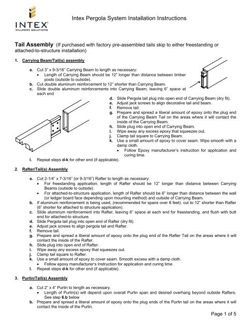
<strong>Intex</strong> <strong>Pergola</strong> <strong>System</strong> <strong>Installation</strong> <strong>Instructions</strong>Tail Assembly (If purchased with factory pre-assembled tails skip to either freestanding orattached-to-structure installation)1. Carrying Beam/Tail(s) assemblya. Cut 3” x 9-3/16” Carrying Beam to length as necessary:• Length of Carrying Beam should be 12” longer than distance between timberposts (outside to outside).b. Cut double aluminum reinforcement to 12” shorter than Carrying Beam.c. Slide double aluminum reinforcements into Carrying Beam, leaving 6” space ateach endd. Slide <strong>Pergola</strong> tail plug into open end of Carrying Beam (dry fit).e. Adjust jack screws to align decorative tail and beam.f. Remove tail.g. Prepare and spread a liberal amount of epoxy onto the plug endof the Carrying Beam Tail on the areas where it will contact theinside of the Carrying Beam.h. Slide plug into open end of Carrying Beam.i. Wipe away any excess epoxy that squeezes out.j. Clamp tail square to Carrying Beam.k. Use a small amount of epoxy to cover seam. Wipe smooth with adamp cloth.• Follow Epoxy manufacturer’s instruction for application andcuring time.l. Repeat steps d-k for other end (if applicable).2. Rafter/Tail(s) Assemblya. Cut 2-1/4” x 7-3/16” (or 9-3/16”) Rafter to length as necessary:• For freestanding application, length of Rafter should be 12” longer than distance between CarryingBeams (outside to outside).• For attached-to-structure application, length of Rafter should be 6” longer than distance between the wall(or ledger board face depending upon mounting method) and outside of Carrying Beam.b. If aluminum reinforcement is being used, (recommended for spans over 8 feet). cut to 12” shorter than Rafter(6” shorter for attached to structure application).c. Slide aluminum reinforcement into Rafter, leaving 6” space at each end for freestanding, and flush with buttend for attached-to structure.d. Slide <strong>Pergola</strong> tail plug into open end of Rafter (dry fit).e. Adjust jack screws to align pergola tail and Rafter.f. Remove tail.g. Prepare and spread a liberal amount of epoxy onto the plug end of the Rafter Tail on the areas where it willcontact the inside of the Rafter.h. Slide plug into open end of Rafter.i. Wipe away any excess epoxy that squeezes out.j. Clamp tail square to Rafter.k. Use a small amount of epoxy to cover seam. Smooth excess with a damp cloth.• Follow epoxy manufacturer’s Instruction for application and curing timel. Repeat steps d-k for other end (if applicable).3. Purlin/Tail(s) Assemblya. Cut 2” x 4” Purlin to length as necessary.• Length of Purlin(s) will depend upon overall Purlin span and desired overhang beyond outside Rafters.See step 6.b belowb. Prepare and spread a liberal amount of epoxy onto the plug ends of the Purlin tail on the areas where it willcontact the inside of the Purlin.Page 1 of 5
c. Slide plug into open end of Purlin.d. Wipe away any excess epoxy that squeezes out.e. Clamp tail square to Purlin.f. Use a small amount of epoxy to cover seam. Smooth excess with a damp cloth.• Follow epoxy manufacturer’s Instruction for application and curing timeg. Repeat b-f for other end (if applicable).<strong>Pergola</strong> <strong>Installation</strong>, Freestanding (If pergola will be attached-to-structure, skip to step # 7)4. Carrying Beam <strong>Installation</strong>a. Attach Carrying Beam brackets using stainless #10-32 x 1½” screws totop of timber posts. If a post top/lid is being used, as with the <strong>Intex</strong>Column Wrap kit, center the post top/lid on top of the timber post andattach the brackets through the lid into the timber post.b. Bracket opening should be set in the direction of the Carrying Beam.c. Place Carrying Beam onto brackets.d. Center the Carrying Beam so that each end projects equally past thepostse. With the beam is in the correct position drill a 1/8” pilot hole into eachscrew hole on the sides of the brackets.f. Attach bracket to beam using stainless #10-32 x 1½” screwsg. Repeat with other Carrying Beam.5. Rafter <strong>Installation</strong>a. Once both Carrying Beans are installed, set one Rafter in place and center so that each tail end projectsequally past the Carrying Beams.b. Mark the under side of the Rafter at the inside and outside of the Carrying Beam at each end. These marksmay be visible after Rafters are installed, so use light pencil or other removable marking.c. Remove Rafter and turn upside down.d. Align all remaining Rafters next to the marked Rafter, andtransfer lines across to all.e. Center a Rafter bracket between the marked lines, with thefour center holes countersink up. Note that the scribed lineson the opposite side of the bracket are used to center thebracket across the Rafter.f. With the bracket centered between the marked lines andacross the Rafter, drill 1/8” pilot holes in each of the 4 holesg. Attach the bracket to the Rafter using stainless #10-32 x1½” screwsh. Repeat steps e-g for all Rafter brackets.i. Measure center to center of the timber posts and divide thismeasurement by the number of rafter spaces (you should have one more Rafter than the number of spaces).This is the center line spacing to set each Rafter.j. Mark both Carrying Beams with center line measurements for all the Rafters to confirm spacing beforeinstallationk. Place Rafters on Carrying Beams and center on marksl. Drill 1/8” pilot holes and attach Rafter brackets to Carrying Beams using stainless #10-32 x 1½” screws6. Purlin or Lath <strong>Installation</strong>a. Once all Rafters are installed, measure the distance between the outside edges of the outer two Rafters.b. Determine the amount of overhang desired for your application. Typical Purlin overhang would be 8” to 12” oneach end, and Lath overhang would be 6” to 8”. Add twice the overhang desired to the measured distance.This is the overall Purlin or Lath length. If using Purlin, this calculation is necessary prior to installing tails instep 3.a.above.c. Once all Purlin or Lath are sized, set one in place and center across rafters with equal overhang at each end.Mark the under the side of the Purlin or Lath at the outside of the outer Rafter each end.d. Remove Purlin or Lath and turn upside down.Page 2 of 5
e. Align all remaining Purlin or Lath next to the marked one, and transfer lines across to all. These marks maybe visible after Purlin or Lath are installed, so use light pencil or other removable marking.f. Measure center to center of the Carrying Beams and divide this measurement by the number of Purlin or Lathspaces (you should have one more Purlin or Lath than the number of spaces). This is the center line spacingto set each Purlin or Lath.g. Mark both end rafters with center line measurements for all thePurlin or Lath to confirm spacing before installation.h. Place Purlin or Lath across Rafters and center to marks.i. Purlin or Lath should be secured with a screw into the Rafter ateach intersection along the two outside Rafters, and then everyother Rafter for the remainder of the intersections. Insure thatPurlin or Lath are straight along their entire length beforesecuring with screws:• If using Purlin, drill 1/8” pilot holes through the top and bottomof the Purlin into the Rafter and secure with 4-1/2” stainlessor coated screws.• If using Lath, secure with stainless #10-32 x 1½” screws<strong>Pergola</strong> <strong>Installation</strong>, Attached-to-Structure7. Carrying Beam <strong>Installation</strong>a. Attach Carrying Beam brackets using stainless #10-32 x 1½” screws to top of timber posts. Note; if a posttop/lid is being used, as with the <strong>Intex</strong> Column Wrap kit, center the post top/lid on top of the timber post andattach the brackets through the lid into the timber post.b. Bracket opening should be set in the direction of the Carrying Beam.c. Place Carrying Beam onto brackets.d. Center the Carrying Beam so that each end projects equally past the postse. Once the beam is in the correct position drill a 1/8” pilot hole into each screw hole on the sides of thebrackets.f. Attach bracket to beam using stainless #10-32 x 1½” screws.8. Ledger Board/Cover <strong>Installation</strong> where Rafter ends rest on top of Ledger Board Cover(<strong>Intex</strong> recommends that a double pressure treated 2 x 10 be used as the structural ledger board)a. Transfer height from top of Carrying Beam to wall, measure down 5/8” and snap line.b. Align the top of the structural ledger board with the snap line and attach using appropriate fastening methods.Counter sink screws or bolts to preclude interference with Ledger Board Cover.c. Fit Ledger Board Cover over structural ledger board and attach using stainless steel finish nails.9. Ledger Board/Cover <strong>Installation</strong> where Rafter ends mount to face of Ledger Board Cover(<strong>Intex</strong> recommends that a double pressure treated 2 x 10 be used as the structural ledger board)a. Transfer height from top of Carrying Beam to wall, measure up 3/8” and snap line.b. Align the bottom of the structural ledger board with the snap line and attach using appropriate fasteningmethods. Counter sink screws or bolts to preclude interference with Ledger Board Cover.c. Fit Ledger Board Cover over structural ledger board and attach using stainless steel finish nails.10. Rafter <strong>Installation</strong> where Rafter ends rest on top of Ledger Board Covera. Once the Carrying Beam and the Ledger Board Cover are installed, place one Rafter with the flat butt end ontop of the Ledger Board Cover, tight against the wall.b. Mark the under side of the Rafter at the inside and outside of the Carrying Beam and at the outside of theLedger Board Cover. These marks may be visible after Rafters are installed, so use light pencil or otherremovable marking.c. Remove Rafter and turn upside down.d. Align all remaining Rafters next to the marked Rafter, and transfer lines across to all.Page 3 of 5
This is the overall Purlin or Lath length. If using Purlin, this calculation is necessary prior to installing tails instep 3.a.abovec. Once all Purlin or Lath are sized, set one in place and center across rafters with equal overhang at each end.Mark the under the side of the Purlin or Lath at the outside of the outer Rafter each end.d. Remove Purlin or Lath and turn upside down.e. Align all remaining Purlin or Lath next to the marked one, and transfer lines across to all. These marks maybe visible after Purlin or Lath are installed, so use light pencil or other removable marking.f. Measure from the butt end of the Rafter to the center of the Carrying Beam and divide this measurement bythe number of Purlin or Lath spaces (you should have one more Purlin or Lath than the number of spaces).This is the center line spacing to set each Purlin or Lath.g. Mark both end rafters with center line measurements for all the Purlin or Lath to confirm spacing beforeinstallation.h. Place Purlin or Lath across Rafters and center on marks.i. Purlin or Lath should be secured with a screw into the Rafter at each intersection along the two outsideRafters, and then every other Rafter for the remainder of the intersections. Insure that Purlin or Lath arestraight along their entire length before securing with screws:• If using Purlin, drill 1/8” pilot holes through the top and bottom of the Purlin into the Rafter and secure with4-1/2” stainless or coated screws.• If using Lath, secure with stainless #10-32 x 1½” screwsNOTE: For any application in these instructions that call for /epoxy INTEX recommends TRIMBONDER 2 partepoxy or BOND AND FILL 2 part epoxy.Carrying Beam BracketRafter BracketLedger Board Bracket(shown with filler plate usedwith 9-3/16" rafters)Double aluminumreinforcement for CarryingBeamAluminum reinforcement for9-3/16" rafterAluminum reinforcement for7-3/16" rafterPost top/LidDecorative TailPage 5 of 5