Piston-pumps - WAGNER-Group
Piston-pumps - WAGNER-Group
Piston-pumps - WAGNER-Group

Create successful ePaper yourself
Turn your PDF publications into a flip-book with our unique Google optimized e-Paper software.
EDITION 06/ 2008OPERATING MANUALPART NO. DOC10585118 cm 3 , 130 cm 3Contents1 ABOUT THESE INSTRUCTIONS 51.1 Languages 51.2 Warnings, notes and symbols in these instructions 52 GENERAL SAFETY INSTRUCTIONS 62.1 Safety instructions for the operation 62.1.1 Electrical equipment 62.1.2 Personnel qualifications 62.1.3 A safe work environment 62.2 Safety instructions for staff 62.2.1 Safe handling of <strong>WAGNER</strong> spray units 72.2.2 Earth the unit 72.2.3 Material hoses 72.2.4 Cleaning 82.2.5 Handling hazardous liquids, varnishes and paints 82.2.6 Touching hot surfaces 82.3 Correct use 82.4 Use in an explosion hazard area 92.4.1 Correct use 92.4.2 Explosion protection identification 92.4.3 Safety instructions 92.5 German regulations and guidelines 103 PRODUCT LIABILITY AND WARRANTY 113.1 Important notes on product liability 113.2 Warranty 113.3 CE-Conformity 124 DESCRIPTION 134.1 Field of application 134.1.1 Using in accordance with the instructions 134.1.2 Processing materials 134.1.3 Typical applications 134.2 Scope of supply 144.3 Data 144.3.1 Materials of paint wetted parts 144.3.2 Recommended V-packings 154.3.3 Technical data 154.3.4 Dimensions and connections 174.3.5 Volume flow 184.3.6 Performance diagrams 184.4 Functions 204.4.1 Pump 204.4.2 Pressure regulator unit 214.4.2.1 Pressure regulator unit for Airless (optional) 214.4.2.2 Pressure regulator unit for Aircoat (optional) 214.4.3 High-pressure filter (optional) 224.4.3.1 Standard HP-filter (optional) 224.4.3.2 Filter-relief combination (optional) 223
EDITION 06/ 2008OPERATING MANUALPART NO. DOC10585118 cm 3 , 130 cm 3Contents5 STARTING UP AND OPERATING 235.1 Set up and connect 235.1.2 Earthing 245.2 Starting up 265.2.1 Safety notes 265.2.2 Filling with separating fluid 275.2.3 Basic cleaning 285.2.4 Filling with working material 285.3 Working 295.3.1 Spraying (Spray pack 22-18S) 295.3.2 Working break 295.3.3 Shutting down and cleaning 305.4 Long-term storage 306 TROUBLESHOOTING AND MAINTENANCE 316.1 Eliminating faults 316.2 Maintenance 327 ACCESSORIES 347.1 Accessories for 3-130S pump 347.2 Accessories for 22-18S pump 368 SPARE PARTS 408.1 How to order spare parts? 408.2 Over views modules 418.3 Air motor 438.3.1 Air motor NW75 438.4 Material <strong>pumps</strong> 468.4.1 Material pump 18S 468.4.2 Material pump 130S 498.5 High-pressure filter 528.6 Filter-relief combination 548.7 Pressure regulator unit Airless 558.8 Pressure regulator unit AirCoat 558.9 Stand 568.10 Pneumatic carriage 578.11 Pneumatic carriage CH-Star with upper hopper 584
EDITION 06/ 2008OPERATING MANUALPART NO. DOC10585118 cm 3 , 130 cm 31 ABOUT THESE INSTRUCTIONS 1.1 LANGUAGES 105850 105851105852 105853105854 105855105857 105856 105858 --1.2 WARNINGS, NOTES AND SYMBOLS IN THESE INSTRUCTIONSWarning instructions in this manual point out particular dangers to users and equipmentand state measures for avoiding the hazard. These warning instructions fall into the followingcategories:Danger - imminent danger. Non-observance will resultin death, serious injury and serious material damage. Warning - possible danger. Non-observance can resultin death, serious injury and serious material damage. Caution - a possibly hazardous situation. Non-observancecan result in minor injury.Caution - a possibly hazardous situation. Non-observancecan cause material damage. Note - provide information on particular characteristics and how to proceed.5
EDITION 06/ 2008OPERATING MANUALPART NO. DOC10585118 cm 3 , 130 cm 32 GENERAL SAFETY INSTRUCTIONS2.1 SAFETY INSTRUCTIONS FOR THE OPERATION 2.1.1 ELECTRICAL EQUIPMENT 2.1.2 PERSONNEL QUALIFICATIONS 2.1.3 A SAFE WORK ENVIRONMENT 2.2 SAFETY INSTRUCTIONS FOR STAFF 6
EDITION 06/ 2008OPERATING MANUALPART NO. DOC10585118 cm 3 , 130 cm 32.2.1 SAFE HANDLING OF <strong>WAGNER</strong> SPRAY UNITSThe spray jet is under pressure and can cause dangerous injuries.Avoid injection of paint or cleaning agents: Never point the spray gun at people. Never reach into the spray jet. Before all work on the unit, in the event of work interruptions and functionalfaults:– Switch off the energy/compressed air supply.– Secure the spray gun against actuation.– Relieve the pressure from the spray gun and unit.– By functional faults: Identify and correct the problem, proceed as described inchap. „Trouble shooting“.In the event of skin injuries caused by paint or cleaning agents: Note down the paint or cleaning agent that you have been using. Consult a doctor immediately.Avoid danger of injury through recoil forces: Ensure that you have a firm footing when operating the spray gun. Only hold the spray gun briefly in any one position.2.2.2 EARTH THE UNITElectrostatic charges can occur on the unit due to the electrostatic charge and the flowspeed involved in spraying.These can cause sparks and flames upon discharge. Ensure that the unit is always earthed. Earth the work pieces to be coated. Ensure that all persons inside the working area are earthed, e.g. that they are wearingantistatic shoes. When spraying, wear antistatic gloves to earth yourself via the spray gun handle.2.2.3 MATERIAL HOSES 7
EDITION 06/ 2008OPERATING MANUALPART NO. DOC10585118 cm 3 , 130 cm 32.2.4 CLEANING 2.2.5 HANDLING HAZARDOUS LIQUIDS, VARNISHES AND PAINTS 2.2.6 TOUCHING HOT SURFACES 2.3 CORRECT USE 8
EDITION 06/ 2008OPERATING MANUALPART NO. DOC10585118 cm 3 , 130 cm 32.4 USE IN AN EXPLOSION HAZARD AREA2.4.1 CORRECT USE 2.4.2 EXPLOSION PROTECTION IDENTIFICATION 2.4.3 SAFETY INSTRUCTIONS 9
EDITION 06/ 2008OPERATING MANUALPART NO. DOC10585118 cm 3 , 130 cm 3 2.5 GERMAN REGULATIONS AND GUIDELINESa) BGV D15 Working with liquid ejection devicesb) BGV D25 Using coating materialsc) CHV 9 Regulations on flammable liquidsd) BGR 104 Explosion protection rulese) BGR 132 Avoiding ignition risksf ) BGR 180 Setting up for cleaning with solvents for cleaning workpieces withsolventsg) ZH 1/406 Guidelines for liquid ejection devicesh) BGI 740 Painting rooms and equipmentNote: All titles can be ordered from Heymanns Publishing House in Cologne or downloadfrom Internet.10
EDITION 06/ 2008PART NO. DOC10585118 cm 3 , 130 cm 3OPERATING MANUAL3 PRODUCT LIABILITY AND WARRANTY3.1 IMPORTANT NOTES ON PRODUCT LIABILITY 3.2 WARRANTY 11
EDITION 06/ 2008PART NO. DOC10585118 cm 3 , 130 cm 3OPERATING MANUAL3.3 CE-CONFORMITYHerewith we declare that the supplied version of:Pneumatic <strong>pumps</strong> and Spraypacks with article no:Type 22-18S 3-130S105082 109046105083 109047109048Complies with the following guidelines:98/37/EG 94/9/EG (Atex-directives)Applied standards, in particular:DIN EN ISO 12100-1 2004-04 DIN EN ISO 3746 1995-12 DIN EN 13463-1 2002-04DIN EN ISO 12100-2 2004-04 DIN EN ISO 14121-1 2007-09 DIN EN 13463-5 2004-03DIN EN ISO 13732-1 2006-12 DIN EN 1127-1 2008-02DIN EN 809 1998-10 DIN EN 12621 2006-05Applied national technical standards and specifications, in particular:BGR 500 Part 2 chap. 2.29 and chap. 2.36 BGR 104 BGR 132 (ZH 1/200)Marking:II 2G IIB T3CE Certificate of ConformityThe certificate is enclosed with this product.The certificate of conformity can be reorderedfrom your <strong>WAGNER</strong> representative, quoting the product and serial number.Part number:<strong>Piston</strong> <strong>pumps</strong> 10591512
EDITION 06/ 2008PART NO. DOC10585118 cm 3 , 130 cm 3OPERATING MANUAL4 DESCRIPTION4.1 FIELD OF APPLICATION4.1.1 USING IN ACCORDANCE WITH THE INSTRUCTIONSThe pneumatic piston pump is suitable for process liquid materials according chapter4.1.2..4.1.2 PROCESSING MATERIALSApplication 22-18S 3-130SWater based lacquers and paints ➚ ➚Solvent based lacquers and paints ➚ ➚Primers ➟ ➟Epoxy and polyurethane paints and lacquers ➚ ➚Synthetic materials ➘ ➟Wax based under seal ➘ ➘LegendRecommended ➚ limited suitability ➟ less suitable ➘CAUTIONAbrasive materials and pigments!Greater wear of the parts carrying the material Do not use any grainy and abrasive materials with large, sharp-edged pigments. Use suitable combinations of devices (packages, valves etc.).SIHI_0011_GB4.1.3 TYPICAL APPLICATIONSApplication 22-18S 3-130SFurniture industry ➚ ➚Kitchen manufacturers ➚ ➚Joinery ➚ ➚Window factories ➟ ➟Steel fabrication ➘ ➟Construction of vehicles ➚ ➚Offshore ➘ ➘LegendRecommended ➚ limited suitability ➟ less suitable ➘13
EDITION 06/ 2008PART NO. DOC10585118 cm 3 , 130 cm 3OPERATING MANUAL4.2 SCOPE OF SUPPLYPneumatic piston pumpConsisting of:- Material pump- Air motor- Connection elementsThe scope of supply includes also:Separating fluid 250 ml; 250 cc Part No.: 9992504Adapter NPS 3/8“ -I- NPS 1/4“ -A Part No.: 367562Adapter NPS 3/8“ -I- M16x1.5 -A Part No.: 367563Open-end wrench SW 46/ SW 41 Part No.: 115883Earthing cable assy. 3 m; 9.84 ft Part No.: 236219CE-Declaration of Conformity See chapter 3Operating manual German Part No.: 105850An operating manual in the local language See chapter 1The delivery note shows the exact scope of delivery.Accessories see chapter 7.4.3 DATA4.3.1 MATERIALS OF PAINT WETTED PARTSHousing<strong>Piston</strong>Valve ballsValve seatsO-ringsV-packingStainless steelStainless steel, hard chromium platedStainless steelStainless steelTeflonStandard PE/TGPE = Polyethylene UHMWTG = Teflon (PTFE) with graphite14
EDITION 06/ 2008OPERATING MANUALPART NO. DOC10585118 cm 3 , 130 cm 34.3.2 RECOMMENDED V-PACKINGSWagner V-packings are manufactured in four different materials:Code Material ColourL Leather dark brownTG Teflon with graphite blackPE Polyethylene UHMW transparentT Teflon whiteEach material has the following properties, which influence the packings:L TG PE TMechanical stability poor good good poorCoefficient of friction poor very good good very goodSealing capacity good* good good goodChemical resistance orpoor good very good very goodreactivityTemperature stability good poor-good very good poor* for abrasive materialsStandard combinationsStandard pneumatic <strong>pumps</strong>Heavy duty (HD) <strong>pumps</strong>Hardener pump in 2C systemsPE/TGPE/LPE/T4.3.3 TECHNICAL DATADescription Technical data Units 22-18S 3-130STransmission ratio 22 :1 3 : 1Flow volume per double stroke (DS) cm³18 130ccMaxi. operating pressureMPabarpsi17.617625502.424348Maxi. possible strokes in operation DH/minDS/min60 60Min. Maxi. air inlet pressureØ air inlet connection (female)Min. Ø compressed air hoseAir consumptionat 0.6 MPa; 6 bar; 87 psi per DSSound pressure level at maxi.permissible air pressure*.MPabarpsiZollInchmmInchnlscf0.25-0,82.5-836-1160.25-0,82.5-836-116R 1/4“ R 1/4“90.3530.11dB(A) 8090.3530.1115
EDITION 06/ 2008OPERATING MANUALPART NO. DOC10585118 cm 3 , 130 cm 3Description Technical data Units 22-18S 3-130SSound pressure level at 0.6 MPa; 6 dB(A) 75bar; 87 psi air pressure*Sound pressure level at 0.4 MPa; 4 dB(A) 70bar; 58.01 psi air pressure*Ø piston of air motormmInch753753Ø material inlet connection (male) M36x2 M36x2Ø material outlet connection(female)WeightkglbNPSM 3/8“ / NPS 1/4“ / M16x1.55.111.2pH range of the material pH 3.5 ÷ 9Maxi. material pressure at pump inlet MPabarpsi220290Range of material temperature °C°FRange of the ambient temperature °C°F+5 ÷ +80+41 ÷ +176+5 ÷ +60+41 ÷ +140Allowable sloping position at work
EDITION 06/ 2008OPERATING MANUALPART NO. DOC10585118 cm 3 , 130 cm 34.3.4 DIMENSIONS AND CONNECTIONS22-18Smm (inch)104 (4.10)3-130Smm (inch)104 ( 4.10)R1/4”409 (161.00)213 (8.39)(196) (7.71)NPSM3/8”NPSM1/4”*B_01102*M16x1.5M36x2415 (16.34)356 (14.02)NPSM3/8”NPSM1/4”=95 (3.74)123 (4.84)80 (3.15)Ø 61 (2.40)Ø 6.3 (0.25)65 (2.56)=48 (1.89) 15 (0.59)73 (2.87)**M16x1.5R1/4”* The adapters are components of thebasic equipment59(2.32)M36x2B_01103Wall mountmm (inch)B_011043 (1.18)17
EDITION 06/ 2008OPERATING MANUALPART NO. DOC10585118 cm 3 , 130 cm 34.3.5 VOLUME FLOWWagner AL Nozzlesat7 MPa70 bar1015 psiVolume flow in l/ min.*at10 MPa100 bar 1450psiat15 MPa150 bar 2175psiø inch ø mm Spray angle0.007 0.18 40° 0.1650 0.2000 0.24000.009 0.23 20-30-40-50-60° 0.2060 0.2500 0.3090 22-18S0.011 0.28 10-20-30-40-50-60° 0.2950 0.3450 0.42600.013 0.33 10-20-30-40-50-60-80° 0.4530 0.5280 0.66000.015 0.38 10-20-30-40-50-60-80° 0.5770 0.6720 0.81300.017 0.43 20-30-40-50-60-70° 0.7310 0.7860 1.06400.019 0.48 20-30-40-50-60-70-80° 0.9260 1.0920 1.37000.021 0.53 20-40-50-60-80° 1.1430 1.3600 1.69000.023 0.58 20-40-50-60-70-80° 1.3700 1.5900 2.01000.025 0.64 20-40-50-60-80° 1.6200 1.9100 2.40000.027 0.69 20-40-50-60-80° 1.8300 2.1300 2.68000.029 0.75 60° 2.1900 2.5100 3.17000.031 0.79 20-40-50-60° 2.4000 2.7700 3.49000.035 0.90 20-40-50-60° 3.2200 3.7400 4.69000.043 1.10 20-50° 5.0700 6.0400 7.46000.052 1.30 50° 5.1200 6.5000 7.5200* Flow volume refers to water.Maximum ranges for continuous operation at 60 DS/min.4.3.6 PERFORMANCE DIAGRAMSStroke frequency (DH/min.)/ (DS/min)ExampleFluid pressure (bar) (MPa) Air throughput (L/min) / (scfm)Material flow volume water (L/min)/ (gpm)18
EDITION 06/ 2008OPERATING MANUALPART NO. DOC10585118 cm 3 , 130 cm 3Diagram for 22-18S Stroke frequency (DS/min) Fluid pressure Air consumptionMaterial flow volume waterA = 8 bar (0.8 MPa / 116 psi)B = 6 bar (0.6 MPa / 87 psi)C = 4 bar (0.4 MPa / 58 psi)Diagram for 3-130S Stroke frequency (DS/min) Fluid pressure Air consumptionMaterial flow volume waterA = 8 bar (0.8 MPa / 116 psi)B = 6 bar (0.6 MPa / 87 psi)C = 4 bar (0.4 MPa / 58 psi)19
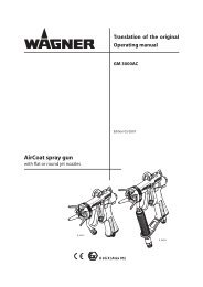
EDITION 06/ 2008OPERATING MANUALPART NO. DOC10585118 cm 3 , 130 cm 34.4 FUNCTIONS4.4.1 PUMP1 Air motor2 Material pump3 Compressed air connection4 Material inlet5 Material outlet6 Filler boring for separating fluid7 Earthing connection8 Ball valveGeneralThe piston pump is driven with compressed air. This compressed air moves up and downthe air piston in the air motor (1) and thus also the pump piston in the material pump (2).At the end of each stroke the compressed air is redirected by a change over valve and thecontrol piston.Working materials are sucked in on the upward stroke and simultaneously conveyed to thegun in both strokes.Air motor (1)The air motor with its pneumatic reverse does not require pneumatic oil.The air motor must be fitted with a safety valve. (see pressure regulator units in chapter4.4.2) The safety valve has been set and sealed at the factory. With pressures over andabove the permissible operating pressure the valve, which is held with a spring, automaticallyopens and releases the excess pressure.SIHI_0026_GBWARNINGOverpressure!Risk of injury from bursting components Never change the safety valve setting.Material pump (2)The material pump has been designed as a piston pump with exchangeable ball valves.The hard chrome-plated pump piston runs in two fixed packings (22-18S) or in one fixedpacking and in one running packing (3-130S) which are self-adjusting by means of a pressurespring, thus resulting in a long life-span.Between the air motor and material pump there is a filler boring for separating fluid (6).20
EDITION 06/ 2008OPERATING MANUALPART NO. DOC10585118 cm 3 , 130 cm 34.4.2 PRESSURE REGULATOR UNIT4.4.2.1 PRESSURE REGULATOR UNIT FOR AIRLESS (OPTIONAL)Part No.: 117270 (see chapter 7)SIHI_0026_GBWARNINGOverpressure!Risk of injury from bursting components Never change the safety valve setting.Thread secured with Loctite 270.Part No. 9992528 (50 ml; 50 cc)Air motorB_011274.4.2.2 PRESSURE REGULATOR UNIT FOR AIRCOAT (OPTIONAL)Part No.: 117275 (see chapter 7)SIHI_0026_GBThread secured with Loctite 270.Part No. 9992528 (50 ml; 50 cc)WARNINGOverpressure!Risk of injury from bursting components Never change the safety valve setting.Air motorB_01128AirCoat gun21
EDITION 06/ 2008OPERATING MANUALPART NO. DOC10585118 cm 3 , 130 cm 34.4.3 HIGH-PRESSURE FILTER (OPTIONAL)4.4.3.1 STANDARD HP-FILTER (OPTIONAL)To ensure problem-free operation it is recommendedthat a <strong>WAGNER</strong> high-pressure filter is used. These havebeen developed especially for the respective pneumatic<strong>pumps</strong>. The filter inserts can be ex-changed depending onthe material to be used.You will find the respective high pressure filters and theirinserts for the device in the part lists. (Section 8.5)121 Connection, material pump2 Two material outlets3 ReturnB_00292Closed2Preferred filterinstallation position3OpenInstallation positionwith filter housingat the down is alsopossibleB_01114B_011134.4.3.2 FILTER-RELIEF COMBINATION (OPTIONAL)Instead of the standard filter the advantageously filter-reliefcombination can be used if only a small volume of material willbe delivered.The filter inserts can be ex-changed depending on the materialto be used. You will find the respective high pressure filters andtheir inserts for the device in the part lists (chapter 8.6).1 Connection, material pump2 Material outlet3 Return4 Relief valve22
EDITION 06/ 2008PART NO. DOC10585118 cm 3 , 130 cm 3OPERATING MANUAL5 STARTING UP AND OPERATING5.1 SET UP AND CONNECTNoteThis pump can be used as part of a spraying system for Airless or AirCoat applications. The components areshown in the accessories, or can be arranged with a spray pack configurator. The nozzles must be selected accordingto the gun instructions.Procedure (possible spray pack variants):1. Assemble the pump on a stand, a trolley (1) or wall mounting (With spray pack orders are already <strong>pumps</strong>on trolley or on stands premounted by the factory).2. Fit pressure regulator unit for Airless or AirCoat (2). Thread into the air inlet for pump secure with Loctite270.3. Fit filter-relief combination (3) or high-pressure filter (3).4. Fit suction system (4) or upper hopper .5. Fit return tube (5).6. Connect high-pressure hose and gun (6) as laid down in the gun-operating manual.Airless-SystemAirCoat-System6216355325 4154B_02758B_01130WARNINGInclined surface!Risk of accidents if the unit rolls away/falls Position the carriage with the piston pump horizontally. If the surface is inclined, position the feet of the carriage towardsthe gradient. Secure the carriage.SIHI_0012_GB23
EDITION 06/ 2008OPERATING MANUALPART NO. DOC10585118 cm 3 , 130 cm 3Cable cross sectionsPump 4 mm²; AWG 11Paint container 6 mm²; AWG 10Conveyor 16 mm²; AWG 5Spraying booth 16 mm²; AWG 5Spraying stand 16 mm²; AWG 5Procedure:1. Fasten the cable lug of the earthing cable on the air motor.2. Clamp the earthing cable clip to a earth connection on site.3. Earth the material (paint) container to a local earth connection.4. Earth the other parts of the system to a local earth connection.B_0112025
EDITION 06/ 2008OPERATING MANUALPART NO. DOC10585118 cm 3 , 130 cm 35.2 STARTING UP5.2.1 SAFETY NOTESEvery time before starting up the following points should be observed as laid down in theoperating instructions:- That it is possible to observe the safety regulations in Chap. 2.- The starting up procedure, has been carried out properly.SIHI_0016_GBWARNINGHigh-pressure spray jet!Danger to life from injecting paint or solvent Never reach into the spray jet. Never point the spray gun at people. Consult a doctor immediately in the event of skin injuries causedby paint or solvent. Inform the doctor about the paint or solventused. Never seal defective high-pressure parts, instead relieve thepressure from them and replace.SIHI_0028_GBWARNINGToxic and/or flammable vapor mixtures!Risk of poisoning and burns Operate the unit in a spraying booth approved for the workingmaterials.-or- Operate the unit on an appropriate spraying wall with the ventilation(extraction) switched on. Observe national and local regulations for the outgoing airspeed.SIHI_0025_GBWARNINGGas mixtures can explode if there is an incompletely filledpump!Danger to life from flying parts Ensure that the piston pump and suction system are alwayscompletely filled with cleaning agent or working medium. Do not spray the unit empty after cleaning.26
EDITION 06/ 2008OPERATING MANUALPART NO. DOC10585118 cm 3 , 130 cm 3Before every start-up, the following points should beobserved as laid down in the operating manual:- Secure gun with safety catch- Check the permissible pressures- Check all connections for leaks- Check hose for damageIt should be ensured that the unit is in the followingstate before carrying out any work on it:- The pressure should be released from the pump andhigh-pressure hose with gun.- The gun should be secured with safety catch.- The air supply should be interrupted.Circulation,return2Closed1Emergency stopIn the case of unforeseen occurrences the ball valve(1) should be closed immediately and the reliefvalve (2) should be on circulation mode.2Return5.2.2 FILLING WITH SEPARATING FLUIDCAUTION<strong>Piston</strong> pump dry run!High wear/damage to the packagesPaint or solvent can escape if the seals are dry Ensure that the separating fluid container is filled with sufficient separating fluid.Filling level 1 cm; 0.4 inches under the pot edge.SIHI_0018_GBPlace the supplied separating fluid into the filling opening (arrow).Filling level: Drive piston of the material pump on upper reverse points and then fillparting solvents in to this are visibleSeparating fluid: Part No. 9992504 (flacon 0.25 l)NoteMaxi. allowed leaning angle of the pump after filling up with parting solvents: ±10°.22-18S 3-130S27
EDITION 06/ 2008OPERATING MANUALPART NO. DOC10585118 cm 3 , 130 cm 35.2.3 BASIC CLEANING1. Place suction hose (7) in a containerwith solvent (6).2. Place empty container (5) under returntube (4.3. Open return valve (3)4. Adjust the air pressure on the pressureregulator (1) so that the pump runsregularly.5. Rinse the system until clean solventflows into the container (5).6. Close return valve (3).7. Point the gun, without nozzle (2) intocontainer (5) and open it.8. Rinse until clean solvent flows from thegun.9. Adjust the air pressure on the pressureregulator (1) on 0 bar.10. When there is no pressure remaining inthe system close gun.11. Secure gun.12. Dispose of the contents of the container(5) according to the local regulations.6534712B_011295.2.4 FILLING WITH WORKING MATERIAL1. Place suction hose (7) in the container with working material (6).Note:If the pump is equipped with a rigid suction system, it should only be diped in into theworking material in maximum to the middle of the inlet housing.2. Place empty container (5) under return tube (4).3. Open return valve (3).4. Adjust the air pressure on the pressure regulator (1) so that the pump runs regularly.5. Close ball valve (3) as soon as pure working material starts coming from the returnhose (4).6. Point the gun, without nozzle (2) into container (5) and open it.7. Adjust the air pressure on the pressure regulator (1) on 0 bar, as soon as pure workingmaterial starts coming from the gun.8. When there is no pressure remaining in the system close gun.9. Secure gun.10. Dispose of the contents of the container (5) according to the local regulations.28
EDITION 06/ 2008OPERATING MANUALPART NO. DOC10585118 cm 3 , 130 cm 35.3 WORKING5.3.1 SPRAYING (SPRAY PACK 22-18S)1. Secure Airless gun (2) or AirCoat gun andplace the appropriate nozzle in the guninstructions.2. Set required working pressure on thepressure regulator (1).3. Optimize the spraying results as laid downin the gun instructions.4. Start work process.31245.3.2 WORKING BREAK1. Close gun.2. Adjust the air pressure on the pressureregulator (1) on 0 bar.3. Release the system by opening the gun.4. Close and secure gun.657B_01129WARNINGHardened material in the spraying system when 2-componentmaterial is worked!Destruction of the pump and injection system Follow the manufacturer‘s working instructions, particularly regardingthe pot life. Rinse thoroughly before the end of the pot life.SIHI_0013_GB29
EDITION 06/ 2008OPERATING MANUALPART NO. DOC10585118 cm 3 , 130 cm 35.3.3 SHUTTING DOWN AND CLEANINGNoteThe device should be cleaned for maintenance purposes, etc. Ensure that no remainingmaterial dries and sticks.Procedure:1. Working break -> carry out Paragraph 5.3.2.2. Basic cleaning -> carry out Paragraph 5.2.3.3. Maintain the gun as laid down in the operating instructions.4. Clean and check the suction system and, in particular, the suction filter.5. When using a high-pressure filter: Clean and check the filter insert and filter body.6. Clean the outside of the system.SIHI_0014_GBWARNINGBrittle filter pressure regulator!The container on the filter pressure regulator becomes brittlethrough contact with solvents and can burstFlying parts can cause injury Do not clean the container on the pressure regulator with solvent.7. Put the whole system back together.8. Check the level of the separating fluid -> Paragraph 5.2.2.9. Fill the system with solvent as laid down in Paragraph 5.2.4 „Filling with workingmaterial“.SIHI_0025_GB5.4 LONG-TERM STORAGEWARNINGGas mixtures can explode if there is an incompletely filledpump!Danger to life from flying parts Ensure that the piston pump and suction system are alwayscompletely filled with cleaning agent or working medium. Do not spray the unit empty after cleaning.If storing the system for a prolonged period of time, thorough cleaning and corrosion protectionare necessary. Replace the water or solvent in the material pump with a suitablepreserving oil. Top up separating fluid.Procedure:1. Carry out Paragraph 5.3.3 „Shutting down and cleaning“, points 1 through 9.2. Cleaning with preserving agent acc. Paragraph 5.2.3.3. Protect the air motor with pneumatic oil: connect an oiler to the compressed air inletand run for a few double strokes.30
EDITION 06/ 2008PART NO. DOC10585118 cm 3 , 130 cm 3OPERATING MANUAL6 TROUBLESHOOTING AND MAINTENANCE6.1 ELIMINATING FAULTSProblem Cause RemedyThe pump does notworkAir motor does not work or stopsOpen and close ball valve on thepressure regulator unit or disconnectcompressed air supply shortly.No pressure indication (pressure regulatordefect)Spray nozzle is cloggedInsufficient supply of compressed airFilter insert in spray gun or high-pressurefilter is cloggedMaterial feed pump or high-pressure hoseare blocked (e.g., two-component materialhardened)Bad spraying results See gun instructionsIrregular operation Viscosity too highof material feed Spraying pressure to lowpump: spray jetcollapses (pulsation)Valve stuckPump runs evenly,however does notsuck up materialPump runs whenthe gun is closedAir motor iced upForeign body in suction valveDiameter of the compressed air line toosmallValves, packings or pistons wornUnion nut of the suction system is loose,pump is taking in airSuction filter cloggedBall in suction or piston valve is stickingPackings, valves, pistons wornA lot of condensation water in the airsupply.If the problem is not listed above consult your <strong>WAGNER</strong> Service Center.Disconnect compressed air supplyshortly or repair or change pressureregulatorClean nozzle as laid down in theinstructionsCheck compressed air supplyClean the parts and use an appropriatespraying materialDismantle the paint pump and clean,replace high-pressure hoseDilute working materialIncrease incoming air pressure, usesmaller nozzleClean material pump, if necessaryleave to soak in solventDismantle suction valve housing, cleanand check valve seatAssemble a larger incoming line ->technical data, paragraph 4.3.3Replace partsTightenClean filterClean with solvent (if necessary ventdevice)Replace partsInstall a water separator.31
EDITION 06/ 2008OPERATING MANUALPART NO. DOC10585118 cm 3 , 130 cm 36.2 MAINTENANCEWARNINGIncorrect maintenance/repair!Danger to life and equipment damage Only a <strong>WAGNER</strong> service center or a suitably trained person maycarry out repairs and replace parts. Only repair and replace parts that are listed in the chapter "Spareparts catalog". Before all work on the unit and in the event of work interruptions:- Disconnect the control unit from the mains.- Relieve the pressure from the spray gun and unit.- Secure the spray gun against actuation. Observe the operating and service instructions when carryingout all work.SIHI_0048_GB1. Check the level of separating fluid in the separating fluid cup every day, and top up ifnecessary.2. Check and clean the high-pressure filter every day or as required.3. Every shut down should be carried out as laid down in paragraph 5.3.3 !4. Check and replace if necessary hoses, tubes, couplings every days.<strong>WAGNER</strong> recommends to check the whole spray system every year from a technical expert(e.g. <strong>WAGNER</strong> service technician).32
EDITION 06/ 2008OPERATING MANUALPART NO. DOC10585118 cm 3 , 130 cm 333
EDITION 06/ 2008OPERATING MANUALPART NO. DOC10585118 cm 3 , 130 cm 37 ACCESSORIES7.1 ACCESSORIES FOR 3-130S PUMP1, 5582397A3469111240, 634842434945 442420235622MW0.8211817MW1.015 16 19MW0.8 MW1.25MW0.3B_02756MW0.834
EDITION 06/ 2008OPERATING MANUALPART NO. DOC10585118 cm 3 , 130 cm 3List accessories 3-130SPE/TG3-130SPE/T3-130SPE/LPos K Description Part No. Part No. Part No.A <strong>Piston</strong> pump (The standard equipment includes: Pos. 1 (250 ml; 250cc), Pos. 2 , Pos. 11 Pos. 12, Pos. 39, Pos. 48 and Pos. 49).109046 109047 1090481 Separating fluid 250 ml; 250 cc 99925042 Earthing cable assy 3 m; 9.75 ft 2362193 ◆ Maintenance (Airless) 1172707 Column 1150528 Pneumatic carriage 1150829 Wall bracket assy 11507511 ◆ Sealing ring A18x22x2.5 992502412 Reducing nipple with 2 x 60°; G 3/8“ -NPSM 3/8“ 36755515 ◆ Filter DN 25 mm; ID 1 inch, MW 0.8 mm, M28x1.5 25024516 ◆ Filter DN 25 mm; ID 1 inch, MW 1.25 mm, M28x1.5 25024317 ◆ Filter DN 25 mm; ID 1 inch, MW 1.0 mm, M28x1.5 34434118 ◆ Filter DN 13 mm; ID 0.5 inch, MW 0.8 mm, M15x1 25024419 ◆ Suction filter bag MW 0.3 mm 9753120 Barrel suction pipe DN 25 mm; ID 1 inch 11517521 ◆ Suction hose flexibly DN 13 mm; ID 0.5 inch 9707322 ◆ Extension hose DN 25 mm; ID 1 inch 11528523 ◆ Extension hose DN 13 mm; ID 0.5 inch 11528424 Suction elbow M36x2 9707539 Open-ended wrench SW 41/ 46 11588340 High-pressure filter HPF-3 NPSM 3/8“ (Ball valve in steel) 36717542 ◆ Sealing ring AL 997411143 Double nipple G 3/8”- M20x2 36796244 ◆ Return hose DN 13 mm; ID 0.5 inch, M20x2 (incl. Pos. 42 + 43) 36718945 Return tube HPF (incl. pos. 42 and pos. 43) 36718846 Wall holder compl. for high-pressure filter (pos. 40) 36711548 Adapter; NPSM 3/8“ I - NPSM 1/4“ A 36756249 Adapter; NPSM 3/8“ I - M16x1.5 A 36756355 Separating fluid 10 l; 2.6 gal 35694056 Suction system 415 mm; 1.4 ft, DN 25 mm; ID 1 inch 10593163 High-pressure filter HPF-3 NPSM 3/8“ (Ball valve in stainless steel) 367178◆ = Wear parts35
EDITION 06/ 2008OPERATING MANUALPART NO. DOC10585118 cm 3 , 130 cm 37.2 ACCESSORIES FOR 22-18S PUMP271, 5522825,26 25,2629 295051A433936,57, 58, 59AirCoat3538305331Airless37, 60, 61, 6240, 6311 12 54846524948424334323345 4424202332132221MW0.810, 5618 MW0.81417MW1.015 16 19MW0.8 MW1.25MW0.3MW0.887549B_0113136
EDITION 06/ 2008OPERATING MANUALPART NO. DOC10585118 cm 3 , 130 cm 3List accessories 22-18SPE/TG22-18SPE/TPos K Description Part No. Part No.A<strong>Piston</strong> pump (The standard equipment includes: pos. 1 (250 ml; 250 cc),pos. 2 , pos. 11 pos. 12, pos. 39, pos. 48 and pos. 49).105082 1050831 Separating fluid 250 ml; 250 cc 99925042 Earthing cable 3 m; 9.75 ft 2362193 ◆ Maintenance unit Airless 1172704 ◆ Maintenance unit Aircoat 1172755 Filter-Release combination NPSM 3/8“-18 3671357 Column 1150528 Pneumatic carriage 1150829 Wall bracket assy 11507510 Suction system for stand270 mm; 0.9 ft, DN 25 mm; ID 1 inch10593011 ◆ Sealing ring A18x22x2.5 992502412 Reducing nipple with 2 x 60°; G 3/8" -NPSM 3/8“ 36755513 Upper hopper set 5 l; 1.3 gal 36704514 Suction elbow for pos. 13 36695015 ◆ Filter DN 25 mm; ID 1 inch, MW 0.8 mm, M28x1.5 25024516 ◆ Filter DN 25 mm; ID 1 inch, MW 1.25 mm, M28x1.5 25024317 ◆ Filter DN 25 mm; ID 1 inch, MW 1.0 mm, M28x1.5 34434118 ◆ Filter DN 13 mm; ID 0.5 inch, MW 0.8 mm, M15x1 25024419 ◆ Suction filter bag MW 0.3 mm 9753120 Barrel suction pipe DN 25 mm; ID 1 inch 11517521 ◆ Suction hose flexibly DN 13 mm; ID 0.5 inch 9707322 ◆ Extension hose DN 25 mm; ID 1 inch 11528523 ◆ Extension hose DN 13 mm; ID 0.5 inch 11528424 Suction elbow M36x2 9707525 Air cap LV (red) 39491026 Air cap HV (blue) 39491127 AirCoat gun GM 4100AC, 16 MPa; 160 bar; 2321 psi; NPSM 1/4“ 39400228 AirCoat gun GM 4600AC, 16 MPa; 160 bar; 2321 psi; NPSM 1/4“ 39400429 ◆ Nozzle ACF3000 -> nozzle list in gun manual 379HHH...30 Airless gun AG-14, NPSM 1/4“; 27 MPa; 270 bar; 3920 psi257017with standard nozzle holder31 ◆ Nozzle standard ...., 27 MPa; 270 bar; 3920 psi 90HHH32 Adapter M16 - M20 11823133 ◆ Return tube 366290◆ = Wear parts37
EDITION 06/ 2008OPERATING MANUALPART NO. DOC10585118 cm 3 , 130 cm 3List accessories 22-18SPE/TG22-18SPE/TPos K Description Part No. Part No.34 Return tube (for pos. 5) 11585835 ◆ Hose set AC material DN 3; air DN6394100Consisting of paint- air- and protective hose.Material: NPSM 1/4“; 7.5 m; 24.6 ft; DN 3 mm; ID 0.12 inch;27 MPa; 270 bar; 3916 psiAir: G1/4“; 7.5 m; 24.6 ft; DN 6 mm; ID 0.24 inch; 0.8 MPa; 8 bar; 116 psi36 ◆ Hose set AC material DN4; air DN6394101Consisting of paint- air- and protective hose.Material: NPSM 1/4“; 7.5 m; 24.6 ft; DN 4 mm; ID 0.16 inch;27 MPa; 270 bar; 3916 psiAir: G1/4“; 7.5 m; 24.6 ft; DN 6 mm; ID 0.24 inch; 0.8 MPa; 8 bar; 116 psi37 ◆ High-pressure hose Airless, 1/4 NPSM,9984573DN 4 mm; ID 0.16 inch, 7.5 m; 24.6 ft,27 MPa; 270 bar; 3920 psi38 ◆ High-pressure hose Airless, 1/4 NPSM,9984583DN 3 mm; ID 0.12 inch, 7.5 m; 24.6 ft,27 MPa; 270 bar; 3920 psi39 Open-end wrench SW 41/ 46 11588340 High-pressure filter HPF-3 NPSM 3/8“ with ball valve in steel 36717542 ◆ Sealing ring AL 997411143 Double nipple G 3/8”- M20x2 36796244 ◆ Return hose DN 13 mm; ID 0.5 inch, M20x2367189(incl. pos. 42 and pos. 43)45 Return tube HPF (incl. pos. 42 and pos. 43) 36718846 Wall holder compl. for high-pressure filter (pos. 40) 36711548 Adapter; NPSM 3/8“ I -NPSM1/4“ A 36756249 Adapter; NPSM 3/8“ I -M16x1.5 A 36756350 Airless gun AG-14, NPSM 1/4“; 27 MPa; 270 bar; 3920 psi257015with Wagner Tip nozzle holder51 ◆ Nozzle Tip nozzle ...., 27 MPa; 270 bar; 3920 psi 1088HHH52 Airless gun AG-14 with Profi Tip HP,347016NPSM 1/4“; 27 MPa; 270 bar; 3920 psi53 ◆ Nozzle Wagner Profi Tip HP..., 1006HHH54 Trolley compl. fix 10515455 Separating fluid 10 l; 2.6 gal 35694056 Suction system for trolley105931415 mm; 1.4 ft, DN 25 mm; ID 1 inch◆ = Wear parts38
EDITION 06/ 2008OPERATING MANUALPART NO. DOC10585118 cm 3 , 130 cm 3List accessories 22-18SPE/TG22-18SPE/TPos K Description Part No. Part No.57 ◆ Hose set AC material DN 4; air DN 6Consisting of paint- air- and protective hose.Material: NPSM 1/4“; 10 m; 32.8 ft; DN 4 mm; ID 0.16 inch; 27 MPa;270 bar; 3916 psiAir: G1/4“; 10 m; 32.8 ft; DN 6 mm; ID 0.24 inch; 0.8 MPa; 8 bar; 116 psi394101-1058 ◆ Hose set AC material DN 4; air DN 6394101-15Consisting of paint- air- and protective hose.Material: NPSM 1/4“; 15 m; 49.2 ft; DN 4 mm; ID 0.16 inch; 27 MPa;270 bar; 3916 psiAir: G1/4“; 15 m; 49.2 ft; DN 6 mm; ID 0.24 inch; 0.8 MPa; 8 bar; 116 psi59 ◆ Hose set AC material DN 4; air DN 6394101-20Consisting of paint- air- and protective hose.Material: NPSM 1/4“; 20 m; 65.6 ft; DN 4 mm; ID 0.16 inch; 27 MPa;270 bar; 3916 psiAir: G1/4“; 20 m; 65.6 ft; DN 6 mm; ID 0.24 inch; 0.8 MPa; 8 bar; 116 psi60 ◆ High-pressure hose Airless, 1/4 NPSM,9984573-10DN 4 mm; ID 0.16 inch, 10 m; 32.8 ft,27 MPa; 270 bar; 3920 psi61 ◆ High-pressure hose Airless, 1/4 NPSM,9984573-15DN 4 mm; ID 0.16 inch, 15 m; 49.2 ft,27 MPa; 270 bar; 3920 psi62 ◆ High-pressure hose Airless, 1/4 NPSM,9984573-20DN 4 mm; ID 0.16 inch, 20 m; 65.6 ft,27 MPa; 270 bar; 3920 psi63 High-pressure filter HPF-3 NPSM 3/8“ with ball valve in stainless steel 367178◆ = Wear parts39
EDITION 06/ 2008OPERATING MANUALPART NO. DOC10585118 cm 3 , 130 cm 38 SPARE PARTS8.1 HOW TO ORDER SPARE PARTS? SIHI_0048_GBWARNINGIncorrect maintenance/repair!Danger to life and equipment damage Only a <strong>WAGNER</strong> service center or a suitably trained person maycarry out repairs and replace parts. Only repair and replace parts that are listed in the chapter "Spareparts catalog". Before all work on the unit and in the event of work interruptions:- Disconnect the control unit from the mains.- Relieve the pressure from the spray gun and unit.- Secure the spray gun against actuation. Observe the operating and service instructions when carryingout all work.40
EDITION 06/ 2008OPERATING MANUALPART NO. DOC10585118 cm 3 , 130 cm 38.2 OVER VIEWS MODULES3-130SPE+TG3-130SPE+T3-130SPE+LPos Description Qty. Part-No. Part-No. Part-No.A <strong>Piston</strong> pump 3-130S compl. 1 109046 109047 1090481 Air motor NW75 1 1052402 Paint stage 130S 1 109141 109142 1091433 Spring pin 1 99942264 Hexagon screw 6 99072165 Serrated washer 6 99221076 Protective stoppers 2 99993377 Sealing ring 18x22x2.5 Cu 1 99250248 Reducing double nipple 2 x 60°; A G 3/8“- A NPSM 3/8“ 1 3675569 Jam nut 1 998557110 Ball valve 1 999111211 Adapter I NPSM 3/8“- A NPSM 1/4“ 1 36756212 Adapter I NPSM 3/8“- A M16x1.5 1 36756313 Earthing cable compl. 3 m; 9.84 ft 1 23621914 Loctite 270, 50 ml; 50 cc 1 99925281310114635427811912B_0111541
EDITION 06/ 2008OPERATING MANUALPART NO. DOC10585118 cm 3 , 130 cm 38.3 AIR MOTOR8.3.1 AIR MOTOR NW75WARNINGIncorrect maintenance/repair!Danger to life and equipment damage Only a <strong>WAGNER</strong> service center or a suitably trained person maycarry out repairs and replace parts. Only repair and replace parts that are listed in the chapter "Spareparts catalog". Before all work on the unit and in the event of work interruptions:- Disconnect the control unit from the mains.- Relieve the pressure from the spray gun and unit.- Secure the spray gun against actuation. Observe the operating and service instructions when carryingout all work.SIHI_0048_GBPos K Qty Part-No. Description1 1 105240 Air motor NW 75 assy.2 ◆★ 1 9972305 Collar seal3 2 105322 Control bush4 ◆★ 4 9971039 O-ring5 ◆★ 5 9971036 O-ring6 4 9903203 Oval head countersunk screws7 1 105242 Cover assy8 ◆ 1 100333 Stop9 1 9900710 Cap head screw with slit10 1 9950103 Earthing point11 2 9950513 Clamping strap12 3 9900730 Cap head screw with slit13 3 9921504 Spring ring14 1 105321 <strong>Piston</strong>15 1 100323 Washer16 1 100343 Lower sleeve17 1 100345 Compression spring18 1 100344 Upper sleeve◆ = Wearing part★ = Included in service set air motor● = Included are not in the basic equipment, available, however, as additional extra43
EDITION 06/ 2008OPERATING MANUALPART NO. DOC10585118 cm 3 , 130 cm 3Air motor NW7536313235292833277127282935372221229358111210133022631420515181716193835454373423243525B_0110923545436263644
EDITION 06/ 2008OPERATING MANUALPART NO. DOC10585118 cm 3 , 130 cm 3Pos K Qty Part-No. Description19 1 100321 <strong>Piston</strong> rod20 ◆★ 1 9971074 O-ring21 ◆ 1 100211 Drive coupler assy22 ◆★ 3 100326 Damping washer23 1 100356 Nut24 ◆★ 1 9972304 Collar seal25 ◆★ 1 9971075 O-ring26 1 105314 Connecting piece27 2 100335 Guide bushing machined part28 2 9994220 Pressure spring29 ◆ 2 100336 Conductor30 ◆ 1 100328 Control piston31 3 9900335 Socket head cap screw32 3 9922106 Serrated washer33 2 105312 Thread Pin34 1 105204 Cylinder35 ● 9998808 Beacon fast EP236 ● 9992616 Molykote paste37 ● 9992590 Loctite 222, 50 ml; 50 cc38 ● 9992511 Loctite 243, 50 ml; 50 cc● 1 105711 Service-Set air motor NW 75◆ = Wearing part★ = Included in service set air motor● = Included are not in the basic equipment, available, however, as additional extra45
EDITION 06/ 2008PART NO. DOC10585118 cm 3 , 130 cm 3OPERATING MANUAL8.4 MATERIAL PUMPS8.4.1 MATERIAL PUMP 18S231017101186767681911009/ 248981535143536121116221325374205363613B_0111046
EDITION 06/ 2008OPERATING MANUALPART NO. DOC10585118 cm 3 , 130 cm 3WARNINGIncorrect maintenance/repair!Danger to life and equipment damage Only a <strong>WAGNER</strong> service center or a suitably trained person maycarry out repairs and replace parts. Only repair and replace parts that are listed in the chapter "Spareparts catalog". Before all work on the unit and in the event of work interruptions:- Disconnect the control unit from the mains.- Relieve the pressure from the spray gun and unit.- Secure the spray gun against actuation. Observe the operating and service instructions when carryingout all work.SIHI_0048_GBSpare parts list material pump 18S 18 cm 3PE/TG18 cm 3PE/TPos K Qty Description Part No. Part No.1 1 Material pump 18S 105150 1051522 ◆ ★ 1 Ball guide-A 1054263 ◆ 1 Valve seat 1054274 ◆ ★ 1 Ball guide-E 1054285 ◆ ★ 1 E-valve seat 1054296 ◆ ★ 3 Sealing collar PE 22.2/34 1055107 ◆ ★ 2 Sealing collar TG 22.2/34 105511 -7 ◆ ★ 2 Sealing collar T 22.2/34 - 1055148 ◆ ★ 3 Sealing collar PE 15.85/27.5 1055129 ◆ ★ 2 Sealing collar TG 15.85/27.5 105513 -9 ◆ ★ 1 Sealing collar T 15.85/27.5 - 10551510 1 Intermediate housing 10551911 ◆ 1 <strong>Piston</strong> 10596012 1 Intermediate piece 10552213 1 Inlet housing 10552314 ◆ ★ 1 Distance piece 10552415 ◆ ★ 1 O-ring 10552516 1 Washer 10552817 ★ 1 Support ring 105531◆ = Wearing part★ = Included in service set● = Included are not in the basic equipment, available, however, as additional extra47
EDITION 06/ 2008OPERATING MANUALPART NO. DOC10585118 cm 3 , 130 cm 3Spare parts list material pump 18S 18 cm 3PE/TG18 cm 3PE/TPos K Qty Description Part No. Part No.18 ★ 1 Compression ring 10553219 ★ 1 Support ring 10553320 ◆ ★ 1 Ball 994151221 ◆ ★ 1 Ball 994152623 1 Pressure spring 999930424 ◆ ★ 1 Sealing collar TG 15.85/27.5 - 10551325 1 Thread ring 105425100 ◆ 1 Packing assy. ../.. 105980 105982101 ◆ 1 Packing assy. ../.. 105981 10598335 ● Beacon fast EP2 999880836 ● Molykote paste 999261637 ● Loctite 222 (50 ml/ 50 cc) 9992590● 1 Service set 18S PE+TG 105705 -● 1 Service set 18S PE+T - 105706◆ = Wearing part★ = Included in service set● = Included are not in the basic equipment, available, however, as additional extra48
EDITION 06/ 2008OPERATING MANUALPART NO. DOC10585118 cm 3 , 130 cm 38.4.2 MATERIAL PUMP 130SWARNINGIncorrect maintenance/repair!Danger to life and equipment damage Only a <strong>WAGNER</strong> service center or a suitably trained person maycarry out repairs and replace parts. Only repair and replace parts that are listed in the chapter "Spareparts catalog". Before all work on the unit and in the event of work interruptions:- Disconnect the control unit from the mains.- Relieve the pressure from the spray gun and unit.- Secure the spray gun against actuation. Observe the operating and service instructions when carryingout all work.SIHI_0048_GBMaterial pump 130 cm 3 S 130 cm 3PE/TG130 cm 3PE/T130 cm 3PE/LPos K Qty Description Part No. Part No. Part No.1 1 Material pump 109141 109142 1091432 ◆ ★ 2 Securing ring 99226203 ◆ 1 Valve seat 1094364 ◆ ★ 1 Sealing collar TG 42.4/54 1093416 1 Outer screw 1093587 ◆ 1 Tube 1094388 1 Cylinder 1093609 1 Intermediate washer 10940710 ◆ ★ 2 Sealing washer 10941011 1 Pressure spring 999421912 ◆ ★ 3 Sealing collar PE 42.4/54 10934013 ◆ ★ 2 Sealing collar TG 42.4/54 109341 -13 ◆ ★ 1 Sealing collar T 42.4/54 109351 -13 ◆ ★ 1 Sealing collar L 42.4/54 - - 10935214 ◆ ★ 1 Support ring 42.4/54 10934215 ◆ ★ 1 Thrust collar 42.4/54 10934316 ◆ ★ 2 Sealing collar PE 48.3/60 10934417 ◆ ★ 1 Sealing collar TG 48.3/60 109345 - -◆ = Wearing part★ = Included in service set● = Included are not in the basic equipment, available, however, as additional extra49
EDITION 06/ 2008OPERATING MANUALPART NO. DOC10585118 cm 3 , 130 cm 3Material pump 130 cm 3 S23835352014161100124/ 131213121510117161918224103Tighten by hand, until noplay is more present11371096722436 3621B_0111950
EDITION 06/ 2008OPERATING MANUALPART NO. DOC10585118 cm 3 , 130 cm 3Material pump 130 cm 3 S 130 cm 3PE/TG130 cm 3PE/T130 cm 3PE/LPos K Qty Description Part No. Part No. Part No.17 ◆ ★ 1 Sealing collar T 48.3/60 - 109355 -17 ◆ ★ 1 Sealing collar L 48.3/60 - - 10935618 ◆ ★ 1 Scraper ring PE 41/60 10934619 1 Support ring 41/60 10934720 1 Compression ring 41/60 10934821 1 Screwed connector 10943523 ◆ 1 <strong>Piston</strong> 10996024 ◆ ★ 2 Ball 9941505100 ◆ 1 Packing assy ../.. 109961 109963 109965101 ◆ 1 Packing assy ../.. 109962 109964 10996635 ● Beacon fast EP2 999880836 ● Molykote paste 999261637 ● Loctite 222- 50 ml/cc 9992590● 1 Service set 130S PE+TG 109705 - -● 1 Service set 130S PE+T - 109706 -● 1 Service set 130S PE+L - - 109707◆ = Wearing part★ = Included in service set● = Included are not in the basic equipment, available, however, as additional extra51
EDITION 06/ 2008PART NO. DOC10585118 cm 3 , 130 cm 3OPERATING MANUAL8.5 HIGH-PRESSURE FILTER90 Nm; 66 lbftPos. 3 tighten by hand2312Identification ofthe filter31125101100 Nm; 74 lbft3062133307332390 Nm; 66 lbft3180 Nm; 59 lbft20304100 Nm: 74 lbftB_02810Ball valve version in: Steel Stainless steelPos K Qty Description Part No. Part No.1 High-pressure filter HPF-3 3/8” 367175 3671782 1 Filter housing 3679113 1 Union nut 3679124 1 Reducing double nipple with 2 x 60° 3675565 ◆ 1 O-ring 3679146 1 Screwed connector 3679167 1 Distribution housing 36791010 1 Filter support 989424511 ◆ 1 Filter cartridge ** Filter cartridge 200 295721◆ = Wearing part● = Included are not in the basic equipment, available, however, as additional extra52
EDITION 06/ 2008OPERATING MANUALPART NO. DOC10585118 cm 3 , 130 cm 3Ball valve version in: Steel Stainless steelPos K Qty Description Part No. Part No.* Filter cartridge 100 3514068* Filter cartridge 50 3514069* Filter cartridge 20 29156412 ◆ 1 Cone spring 351405820 ◆ 1 Ball valve 9998679 999915921 1 Screw-in screw connection 999868023 2 Lock screw 990712730 ◆ 3 Sealing ring 992502431 1 Adapter I NPSM 3/8“- A NPSM 1/4“ 36756233 ● 1 Loctite 542 50 ml; 50 cc 9992831◆ = Wearing part● = Included are not in the basic equipment, available, however, as additional extraSIHI_0048_GBWARNINGIncorrect maintenance/repair!Danger to life and equipment damage Only a <strong>WAGNER</strong> service center or a suitably trained person maycarry out repairs and replace parts. Only repair and replace parts that are listed in the chapter "Spareparts catalog". Before all work on the unit and in the event of work interruptions:- Disconnect the control unit from the mains.- Relieve the pressure from the spray gun and unit.- Secure the spray gun against actuation. Observe the operating and service instructions when carryingout all work.53
EDITION 06/ 2008OPERATING MANUALPART NO. DOC10585118 cm 3 , 130 cm 38.6 FILTER-RELIEF COMBINATION41790 Nm; 66 lbft16191M16x1.51088827550 Nm; 37 lbft3B_027609NPSM3/8”176NPSM3/8*NPSM1/4”18Pos K Qty Part No. Description1 367135 Filter-relief combination2 1 123469 Filter housing3 1 367564 Adapter I=M20x1.5; A=NPSM 3/8”4 ◆ 1 169248 Relief valve assy5 ◆ 1 – Filter cartridge*34383 * 200 meshes (red)43235 * 100 meshes (yellow) (standard)34377 * 50 meshes (white)89323 * 30 meshes (green)6 ◆ 1 43303 Handle sealing washer7 ◆ 1 43590 Pressure spring8 ◆ 3 9971525 U-Seal9 1 367567 Swivel, assy.10 1 123510 Double socket16 1 9904312 Lock screw17 9992609 Anti-sieze paste18 367562 Adapter I=NPSM 3/8”; A=NPSM 1/4”19 1 115199 Release housing◆ = Wearing parts54
EDITION 06/ 2008OPERATING MANUALPART NO. DOC10585118 cm 3 , 130 cm 38.7 PRESSURE REGULATOR UNIT AIRLESSPos K Qty Part No. Description1 1 117270 Maintenance unit for Airless2 1 117331 Double nipple3 1 117332 Distance nipple4 3 9970149 Sealing ring5 ◆ 1 114324 Pressure gauge6 1 117333 Double nipple7 1 9970150 Sealing ring8 1 114331 Safety valve11 1 9992528 Loctite 27012 ◆ 1 117330 Regulator1112354712 464B_027668◆ = Wearing parts8.8 PRESSURE REGULATOR UNIT AIRCOATPos K Qty Part-No. Description1 1 117275 Maintenance unitfor AirCoat2 1 117331 Double nipple3 1 117332 Distance nipple4 5 9970149 Sealing ring5 ◆ 1 114324 Pressure gauge6 2 117333 Double nipple◆ =Wearing partsPos K Qty Part-No. Description7 1 9970150 Sealing ring8 1 114331 Safety valve9 1 9985691 Fitting T-piece10 1 117335 Pressure gauge11 1 9992528 Loctite 27012 ◆ 2 117330 Regulator◆ =Wearing parts234781911B_02767512104641246455
EDITION 06/ 2008OPERATING MANUALPART NO. DOC10585118 cm 3 , 130 cm 38.9 STAND81534267B_01260Pos K Qty Part No. Description1 1 115052 Stand2 1 105203 Lower part3 1 9922109 Serrated washer4 1 9910102 Hexagon nut5 1 9900206 Hexagon screw6 ◆ 1 9990809 Tube plug7 ◆ 2 9990810 Pipe cap8 1 115053 Upper part◆ = Wearing parts56
EDITION 06/ 2008OPERATING MANUALPART NO. DOC10585118 cm 3 , 130 cm 38.10 PNEUMATIC CARRIAGE627911153410B_012618Pos K Qty Part no. Description1 1 115082 Pneumatic carriage2 1 115373 Upper frame3 ◆ 2 9994924 Rubber tired wheel4 ◆ 2 9921710 Fixed washer5 ◆ 2 9921711 Fixed washer with cap6 ◆ 1 9994103 Handle7 ◆ 1 9910512 Hand-wheel Compact◆ = Wearing partsPos K Qty Part no. Description8 ◆ 1 29774 Trolley foot9 1 115744 Spacer washer10 ◆ 1 115756 Use11 1 115372 Trolley rack◆ = Wearing parts57
EDITION 06/ 2008OPERATING MANUALPART NO. DOC10585118 cm 3 , 130 cm 38.11 PNEUMATIC CARRIAGE CH-STAR WITH UPPER HOPPERPos K Qty Part no. Description1 1 105082 <strong>Piston</strong> pump 22-18S PE+TG;Spare parts see chap. 8.2, 8.3 and 8.4.1 1 105083 <strong>Piston</strong> pump 22-18S PE+T;Spare parts see chap. 8.2, 8.3 and 8.4.2 1 935028 Sticker3 4 9900342 Hexagon socket head cap screw4 4 9910801 Cap nut5 4 9925014 Serrated lock washer6 ◆ 4 9999406 Single caster7 1 3202492 Pipe double nipple8 1 9992846 Angle 90 degrees9 2 9992847 Angle 45 degrees10 1 253426 Union nut11 1 366955 Suction nipple12 1 267313 Suction tube13 1 55721 Run-in14 ◆ 1 97560 Coating15 1 9992833 Loctite 638 green16 1 10722 Potential equalization cable assy17 1 104560 Tube18 ◆ 1 105350 Valve box19 ◆ 1 105352 Sealing screw20 1 350499 Screwed connector M16x1.5 RN 1/421 1 384116 Swivel, assy22 1 9930607 Center-grooved dowel pin23 1 9992590 Loctite 22224 1 9992616 Molykote DX grease25 1 9992129 Bend elbow26 1 128318 Nipple27 1 128319 Union nut28 2 115313 Filter reduction valve29 2 9998677 Pressure gauge D 40 0-1 MPa; 0-10 bar; 0-145 psi30 1 9985691 Fitting T-piece31 1 9983229 Fitting nipple32 1 935049 Plug-in nipple 1/4“ outside thread33 1 9970150 Sealing ring◆ = Wearing parts58
EDITION 06/ 2008OPERATING MANUALPART NO. DOC10585118 cm 3 , 130 cm 34416434241 3940451221940 Nm; 29.5 lbft2024182317212440 Nm; 29.5 lbft35462627343330312825353532291312214111089157415563B_0275759
EDITION 06/ 2008OPERATING MANUALPART NO. DOC10585118 cm 3 , 130 cm 3Pos K Qty Part no. Description34 1 114331 Safety valve35 1 9992528 Loctite 27039 1 340265 Upper hopper with filter disk40 ◆ 1 340427 Upper hopper black41 ◆ 1 3756 Filter disk D 5742 2 9902313 Cylinder self-tapping screw43 2 9920314 Washer44 ◆ 1 340429 Cover45 1 100338 Handle46 1 9994628 Reducing double nipple with 2 x 90°◆ = Wearing parts60
EDITION 06/ 2008OPERATING MANUALPART NO. DOC10585118 cm 3 , 130 cm 361
EDITION 06/ 2008OPERATING MANUALPART NO. DOC10585118 cm 3 , 130 cm 3GermanyJ.<strong>WAGNER</strong> GmbHOtto-Lilienthal-Str. 18Postfach 1120D- 88677 MarkdorfTelephone: ++49/ (0)7544 / 5050Telefax: ++49/ (0)7544 / 505200E-Mail:service.standard@wagner-group.comBelgium<strong>WAGNER</strong> Spraytech Benelux BVVeilinglaan 58B- 1861 WolvertemTelephone: ++32/ (0)2 / 269 4675Telefax: ++32/ (0)2 / 269 7845E-Mail: info@wagner-wsb.euUnited Kingdom<strong>WAGNER</strong> Spraytech (UK) Ltd.The Coach House2 Main RoadGB- Middleton Cheney, OXON OX17 2NDTelephone: ++44/ (0)1295 / 714 202Telefax: ++44/ (0)1295 / 710 100E-Mail: enquiries@wagnerspraytech.co.ukNetherlands<strong>WAGNER</strong> SPRAYTECH Benelux BVZonnebaan 10NL- 3542 EC UtrechtPO Box 16563600 BR MaarssenTelephone: ++31/ (0)30 / 241 4155Telefax: ++31/ (0)30 / 241 1787E-Mail: info@wagner-wsb.euJapan<strong>WAGNER</strong> Spraytech Ltd.2-35, Shinden NishimachiJ- Daito Shi, Osaka, 574-0057Telephone: ++81/ (0)720 / 874 3561Telefax: ++81/ (0)720 / 874 3426E-Mail: marketing@wagner-japan.co.jpSweden<strong>WAGNER</strong> Industrial Solutions Scandinavia ABKarbingatan 28S- 25467 HelsingborgTelephone: ++46/ (0)42 150 020Telefax: ++46/ (0)42 150 035E-Mail: mailbox@wagner.seCzechoslovakia<strong>WAGNER</strong> s.r.o.Na Belidle 1/63C- 15000 Praha 5Telephone: ++420/ (0)2/ 573 123 24Telefax: ++420/ (0)2/ 545 001E-Mail: wagner.s.r.o.@telecom.czSwitzerlandJ.<strong>WAGNER</strong> AGIndustriestrasse 22Postfach 663CH- 9450 AltstättenTelephone: ++41/ (0)71 / 757 2211Telefax: ++41/ (0)71 / 757 2222E-Mail: rep-ch@wagner-group.chDenmark<strong>WAGNER</strong> Spraytech Scandinavia A/SHelgeshøj Allé 28DK- 2630 TåstrupTelephone: ++45/ 43 271 818Telefax: ++45/ 43 43 05 28E-Mail wagner@wagner-group.dkFranceJ.<strong>WAGNER</strong> France S.A.R.L.5, Ave. du 1er Mai – BP 47F- 91122 Palaiseau-CedexTelephone: ++33/ (0)1 / 69 19 46 76Telefax: ++33/ (0)1 / 69 81 72 57E-Mail: division.batiment@wagner-france.frItaly<strong>WAGNER</strong> COLORA S.r.lVia Fermi, 3I- 20040 Burago di Molgora (MI)Telephone: ++39/ 039 / 625021Telefax: ++39/ 039 / 6851800E-Mail: info@wagnercolora.comAustriaJ.<strong>WAGNER</strong> GmbHOtto-Lilienthal-Str. 18Postfach 1120D- 88677 MarkdorfTelephone: ++49/ (0)7544 / 5050Telefax: ++49/ (0)7544 / 505200E-Mail:service.standard@wagner-group.comSpain<strong>WAGNER</strong> Spraytech Iberica S.A.Ctra. N- 340, Km. 1245,4E- 08750 Molins de Rei (Barcelona)Telephone: ++34/ (0)93/ 680 0028Telefax: ++34/ (0)93/ 668 0156E-Mail: info@wagnerspain.comUSAWalter Pilot North America46890 Continental DriveChesterfield, MI 48047 USATelephone: ++1/ 877 / 925-8437Telefax: ++1/ 586 / 598-1457http://www.waltherpilotna.comGB62
CERTIFIED 105851