36 Operator's Manual.. - Marlow-Hunter, LLC
36 Operator's Manual.. - Marlow-Hunter, LLC
36 Operator's Manual.. - Marlow-Hunter, LLC

Create successful ePaper yourself
Turn your PDF publications into a flip-book with our unique Google optimized e-Paper software.
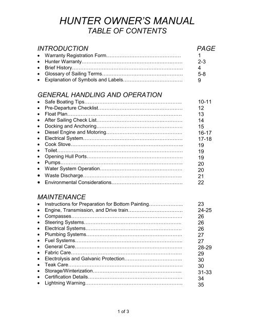
HUNTER OWNER’S MANUALTABLE OF CONTENTSINTRODUCTION· Warranty Registration Form………………………………………· <strong>Hunter</strong> Warranty………………………………………….…………· Brief History………………………………………………………….· Glossary of Sailing Terms….………………………………………· Explanation of Symbols and Labels………………………………GENERAL HANDLING AND OPERATION· Safe Boating Tips…………………………………………………..· Pre-Departure Checklist……………………………………………· Float Plan……………………………………………………………· After Sailing Check List………………………………….…………· Docking and Anchoring…………………………………………….· Diesel Engine and Motoring……………………………………….· Electrical System……………………………………………………· Cook Stove…………………………………………………………..· Toilet…….……………………………………………………………· Opening Hull Ports………………………………………………….· Pumps………………………………………………………………..· Water System Operation………………………………….……….· Waste Discharge………………………………………….………..· Environmental Considerations…………………………………….MAINTENANCE· Instructions for Preparation for Bottom Painting………………...· Engine, Transmission, and Drive train……………………………· Compasses………………………………………………………….· Steering Systems…………………………………………………..· Electrical Systems………………………………………………….· Plumbing Systems………………………………………………….· Fuel Systems………………………………………………………..· General Care………………………………………………………..· Fabric Care………………………………………………………….· Electrolysis and Galvanic Protection……………………………..· Teak Care……………………………………………………………· Storage/Winterization……………………………………………...· Certification Details…………………………………………………· Lightning Warning…………………………………………………..PAGE12-345-8910-111213141516-1717-18191919202021222324-25262626272728-2929303031-3334351 of 3
HUNTER OWNER’S MANUALTABLE OF CONTENTS (CONT’D)DESCRIPTION OF MODEL· Profile with Rig and Sail Dimensions……………………………..· Dimensions, Capacities, etc……………………………………….· Deck Plan and Hardware…………………………………………..· Deck Hardware Parts Listing………………………………………· Accommodation Plan……………………………………………….· Dinette Table Operation……………………………………………· Lifting Points…………………………………………………………· Running Rigging Layout……………………………………………· Mainsheet Rigging………………………………………………….· Arch Installation……………………………………………………..· Boom and Reefing Details…………………………………………· Running Rigging Specifications…………………………………..· Rig Description……………………………………………………..· Standing Rigging Layout……...……………………………………· Spreader Details…………………………………………………….· Standing Rigging Specifications…………………………………..· Standing Rigging Attachments…………………………………….· Rig Tuning Instructions…………………………………………….· Spinnaker Details…………………………………………………...· Engine Compartment Details……………………………………...· Shaft and Propeller…………………………………………………SYSTEMS AND CIRCUITS· Potable Water System……………………………………………..· Waste System……………………………………………………….· Bilge Pumping System……………………………………………..· Through Hulls, Seacocks, and Valves……………………………· Fuel System…………………………………………………………· Propane System…………………………………………………….· Electrical System(See Electrical System Table Of Contents)………· Steering System…………………………………………………….· Anchoring Arrangement……………………………………………· Index………………………………………………………………….PAGE<strong>36</strong>37383940A-40C41A41B42A-1&243444546474849505152-53545556PAGE57585960616263A-166-6869702 of 3
HUNTER OWNER’S MANUALTABLE OF CONTENTS (CONT’D)EQUIPMENT MANUALS AND INFORMATION· Engine <strong>Manual</strong>· Knotmeter and Depthsouder· VHF Radio (except where not provided)· Compass Information· Stereo <strong>Manual</strong>· Furling System <strong>Manual</strong>· Marine Rigging Guide· Winch Maintenance Guide· Steering Maintenance Guide· Sail Maker Information· Water Strainer· Bilge Pump· Toilet <strong>Manual</strong>· Stove <strong>Manual</strong>· Hot Water <strong>Manual</strong>· Microwave <strong>Manual</strong> (except where not provided)· Other:3 of 3
Welcome toTHE HUNTER MARINE FAMILYCongratulations on your new sailing yachtmanufactured by <strong>Hunter</strong> Marine. We haveengineered and constructed your boat to be asfine a yacht as any afloat. In order to get the bestperformance and most enjoyment from your boatyou should be familiar with its various elementsand their functions. For your sailing pleasure andsafety, please take time to study this manual.We stand behind the quality of your boat with awarranty, which you should review. To insure thevalidity of your warranty, please complete theattached card and send it to us within ten (10)days of the purchase date. Section 15 of the U.S.Federal Boat Safety Act requires registration of aboat’s first owner. The warranty data should alsobe recorded in the space below for your ownreference.This manual has been compiled to help youoperate your craft with safety and pleasure. Itcontains details of the craft; equipment suppliedor fitted, systems, and information on operationand maintenance. Please read it carefully, andfamiliarize yourself with the craft before using it. Ifthis is your first sailboat or you are changing to atype of craft you are not familiar with, pleaseensure that you obtain proper handling andoperating experience before you assumecommand of the craft. Your dealer or nationalsailing federation or yacht club will be pleased toadvise you of local sea schools or competentinstructors.PLEASE KEEP THIS MANUAL IN A SAFEPLACE AND HAND IT OVER TO THE NEWOWNER IF YOU SELL THE CRAFT.You should also complete the warranty cards foryour engine, stove, head, electric water pumpand other accessories. These are enclosed in themanufacturers’ manuals that are packaged withyour owner’s manual.OWNER INFORMATION CARDHULL IDENTIFICATION NUMBER IS ON THE STARBOARD AFT SIDE OF THE HULL OR TRANSOM.THIS NUMBER MUST BE GIVEN IN ALL NECESSARY CORRESPONDENCE.HULL NO.DATE DELIVERED TO OWNERYACHT NAMEOWNER NAMESTREET ADDRESSCITY STATE/COUNTRY ZIP CODEHOME PORTENGINE MODEL SERIAL NO. PROPELLER SIZEDEALERPHONESTREET ADDRESSCITY STATE/COUNTRY ZIP CODEPAGE 1
<strong>Hunter</strong> Marine warrants to the first-usepurchaser and any subsequent owner duringthe warranty period, that any partmanufactured by <strong>Hunter</strong> will be free ofdefects caused by faulty workmanship ormaterials<strong>Hunter</strong> warrants to the first-use purchaserand any subsequent owner during thewarranty period that the hull of each boat willbe free from structural defects in materialsand workmanship for a period of five (5)years from the date of delivery to the firstusepurchaser under normal use andservice.This limited warranty applies only to thestructural integrity of the hull and supportingpan/grid or stringer system. Hulls, pan/gridor stringers modified in any way or poweredwith engines other than the type and sizeinstalled or specified by <strong>Hunter</strong> are notcovered by this limited warranty. Theobligation of <strong>Hunter</strong> under this limitedwarranty is restricted to the repair orreplacement of hulls that are determined tobe structurally defective.<strong>Hunter</strong> also warrants to the first-usepurchaser and any subsequent owner duringthe warranty period that the boat will be freefrom gel-coat blistering on underwatersurfaces of the hull, excluding the keel andrudder, for a period of five (5) years from thedate of delivery to the first-use purchaserHUNTER MARINELIMITED WARRANTYLIMITED ONE-YEAR WARRANTYLIMITED FIVE-YEAR HULL STRUCTUREAND BOTTOM BLISTER WARRANTYfor a period of twelve (12) months from thedate of delivery to the first-use purchaserunder normal use and service. During thisperiod, <strong>Hunter</strong> will repair or replace any partjudged to be defective by <strong>Hunter</strong>.under normal use and service. During thisperiod, <strong>Hunter</strong> will supply or reimburse anauthorized <strong>Hunter</strong> dealer for all of the partsand labor required to repair a blisteredunderwater surface of the hull. The laborcost reimbursement will be based on theLabor Allowance Schedule established by<strong>Hunter</strong>. However, if a non-<strong>Hunter</strong> dealerperforms the repair, the repair cost must beauthorized by <strong>Hunter</strong> in advance and bebased on a reasonable number of hours asdetermined by <strong>Hunter</strong>. Transportation,hauling, launching, bottom paint, storage,dockage, cradling rental, rigging andderigging, or other similar costs will not bepaid by <strong>Hunter</strong>. We recommend that therepair be done during a seasonal haul outfor service or storage.The bottom blister warranty is void underthe following circumstances:(1) If the gel-coat has been sanded,sandblasted, or subjected to abrasion orimpact.(2) If the instructions provided in the<strong>Hunter</strong> Owner’s manual regarding bottompreparation techniques are not followed.RESTRICTIONS APPLICABLE TO WARRANTIESThese limited warranties do not cover thefollowing:(1) Paint, window glass, gel-coat,upholstery, engines, engine parts, bilgepumps, stoves, blowers, pressure waterpumps, propellers, shafts, rudders, controls,instruments, keels and equipment notmanufactured by <strong>Hunter</strong>. Any warrantymade by the manufacturer of such items willbe, if possible, given on to the first-usepurchaser.(2) Problems caused by impropermaintenance, storage, cradling, blocking,normal wear and tear, misuse, neglect,accident, corrosion, electrolysis or improperoperation.THIS WARRANTY IS EXPRESSLY IN LIEUOF ANY AND ALL OTHER REMEDIESAND WARRANTIES EXPRESSED ANDIMPLIED, INCLUDING THE WARRANTIESOF MERCHANTABILITY AND FITNESS.SOME STATES OR COUNTRIES DO NOTALLOW LIMITATIONS ON HOW LONG ANIMPLIED WARRANTY LASTS, SO THEABOVE LIMITATION MAY NOT APPLY TOYOU. THE PURCHASERPAGE 2
ACKNOWLEDGES THAT NO OTHERREPRESENTATIONS WERE MADE TO HIMANY CONSEQUENTIAL DAMAGES THATMAY BE INCURRED ARE EXCLUDED ANDJUDGED DEFECTIVE BY HUNTER.SOMESTATES OR COUNTRIES DO NOTALLOW THE EXCLUSION OF INCIDENTALOR CONSEQUENTIAL DAMAGES, SO THEThese limited warranties shall not beeffective unless the <strong>Hunter</strong> WarrantyRegistration Form and Pre-Delivery ServiceRecord, which are furnished with each newboat, are filled out completely and returnedto <strong>Hunter</strong> within fifteen (15) days of delivery.Responsibility for sending the completedRegistration Form remains with the dealer.It is critical that the Warranty RegistrationForm is signed by both the dealer and theowner and returned to <strong>Hunter</strong>. Warrantycoverage cannot be initiated until <strong>Hunter</strong>receives the completed form. All repairsand/orLimited warranties will be transferred to asubsequent purchaser of the boat if:(1) The subsequent purchaser gives<strong>Hunter</strong> written notice of transfer ofownership within thirty (30) days of thetransfer.(2) The notice shall include thename, address and telephone number of theShould a customer wish to have an epoxybarrier applied to the hull, ( ex. InterluxInterprotect 1000/2000, West Systems, VCTar), this will not void the five-year blisterwarranty. This refers to epoxy barriercoatings as mentioned above, not epoxyprimer paints.During the first year of ownership, the firstpurchaser will receive two CustomerSatisfaction Surveys: the first (CSS #1) willbe received shortly after taking delivery andfocuses on the customer’s experience withthe dealer and commissioning of the boat,and the owner’s initial satisfaction. TheHUNTER MARINELIMITED WARRANTYWARRANTY REGISTRATIONTRANSFER OF LIMITED WARRANTIESEPOXY BARRIER COATCUSTOMER SATISFACTION SURVEYOR HER WITH RESPECT TO THE QUALITYAND FUNCTION OF THE BOAT.ABOVE LIMITATION OR EXCLUSION MAYNOT APPLY TO YOU. THIS WARRANTYGIVES YOU SPECIFIC LEGAL RIGHTS, ANDYOU MAY ALSO HAVE OTHER RIGHTSTHAT VARY FROM STATE TO STATE ORCOUNTRY TO COUNTRY.replacements will be made by an authorized<strong>Hunter</strong> dealer, or at the option of <strong>Hunter</strong>, atthe <strong>Hunter</strong> plant. If the repairs are of such anature that the warranty work must beperformed at the <strong>Hunter</strong> plant, the ownershall pay transportation costs to and fromthe <strong>Hunter</strong> plant. The labor costreimbursement will be based on a laborallowance schedule established by <strong>Hunter</strong>and where not applicable, on a reasonablenumber of hours as determined by <strong>Hunter</strong>.An authorized <strong>Hunter</strong> service representativemust approve any repairs and replacementsinadvance.subsequent purchaser, the date ofpurchase, the hull number, and the name ofthe seller of the boat.<strong>Hunter</strong> will mail notice of expiration dates ofthe limited warranties to the subsequentowner. The transfer of the ownership of thewill not extend the expiration dates of thelimited warranties.If an epoxy barrier coat is applied to a<strong>Hunter</strong> vessel, it must be registered with theWarranty Department prior to application ofthe product. If the dealer applies bottompaint only, sanding will not be allowed andthe no sanding system must be used.second survey (CSS #2) is given nine to tenmonths into ownership, and primarily givesthe customer an opportunity to evaluatedealer service capability and the boat’sfunctional systems and characteristics. Bothsurveys are contingent upon receipt of thefirst purchaser’s Warranty Registration form.PAGE 3
HUNTER MARINE’S OWNER AND FOUNDERWARREN R. LUHRSBRIEF BACKGROUNDWarren Luhrs was born in East Orange,New Jersey in 1944 into a family with anestablished tradition in the maritime andtransportation industries. His greatgrandfather,Henry, was a railroad andclipper-shipping pioneer in America,while his great-uncle John helped buildthe famous St. Petersburg to Moscowrailroad for Czar Alexander II.Henry Luhrs owned shares in twentytwodifferent ocean-going vessels –barks, brigs, and schooners - and wasthe principal owner of the bark SophiaR. Luhrs, named for his wife. He wasalso a partner with Albert Sprout, whomanaged the shipyard where the SophiaR. Luhrs was built in Melbridge, Maine.Warren Luhrs’ father Henry worked at asmall boat manufacturer in Morgan,New Jersey, and later started his owncompany, continuing the Luhrs’ familysea tradition during the greatdepression. During World War II herepaired boats and installed icesheathing on their bows for the CoastGuard.After the War, Henry built 27-foot fishingboats and in 1948 began to constructcustom-built pleasure craft. He thenturned to skiffs and in 1952 incorporatedas Henry Luhrs Sea Skiffs, where heconstructed lapstrake sea skiffs usingassembly-line techniques. Henrypersonally “shook down” his prototypeson family trips up the Hudson River toLake Champlain.The sea skiff is a class of boat that hasbeen very popular, owing to itsseaworthiness. It features a sharp bow,which reduces pounding in surf orchoppy seas, and a hull whose forwardsection is rounded below the waterlineto increase stability in rough water or afollowing sea. Such skiffs can either besmooth sided or of a lapstrakeconstruction.Inspired by Henry Ford, Henry Luhrs’aimed to give the average man theopportunity to enjoy the luxury ofboating by building an affordable andreliable boat. He was both designer andengineer, and his progressive newmodels exhibited his talent forinnovation. He successfully changed theline of the bow from straight to curved ata time when the industry trend was astraight square effect, and he is believedto be the first designer-builder topopularize a small boat with a fly bridge.In 1960, Luhrs acquired the UlrichsenBoat Company of Marlboro, NewJersey. It was here that Luhrs’ Alurafiberglass division was located. In 1965,Henry sold his company to BangorArrostook Railroad, which was tobecome the recreational conglomerateBangor-Punta. It was also during thisperiod that Silverton of Tom’s River,New Jersey was purchased by John andWarren Luhrs.Today, Warren R. Luhrs and his brotherJohn own the Luhrs Group of marinemanufacturers, which consists ofSilverton Marine, Mainship MotorYachts, and Luhrs Fishing Boats with itsAlura division, as well as <strong>Hunter</strong> Marine,which exclusively manufacturessailboats.In January of 1996, the Luhrs familytransferred a portion of the Luhrs Groupto its employees through an ESOPprogram.PAGE 4
GLOSSARY OF SAILING TERMSAAback: describes a sail when the windstrikes it on the lee side.Abaft: towards the boat’s stern.Abeam: at right angles to the centerlineof the boat.Aft: at or near the stern.Amidships: the center of the boat,athwartships and fore and aft.Anti-fouling: a poisonous paintcompound used to protect theunderwater part of a hull from marinegrowths.Apparent wind: The direction andspeed of the wind felt by the crew. Itis a combination of true wind and thatcreated by the movement of the boat.Astern: behind the boat; to go asternis to drive the boat in reverse.Athwartships: at right angles to thefore and aft line of the boat.BBack: when a wind backs, it shiftsanticlockwise.Back a sail: to sheet it to windwardso that the wind fills on the side thatis normally to leeward.Backstay: a stay that supports themast from aft and prevents its forwardmovement.Ballast: extra weight, usually lead oriron, placed low in the boat orexternally on the keel to providestability.Ballast keel: a mass of ballast boltedto the keel to increase stability andprevent a keel boat from capsizing.Batten: a light, flexible strip fed into abatten pocket at the leech of the sailto support the roach.Beam: 1, the maximum breadth of aboat; 2, a transverse member thatsupports the deck; 3, on the beammeans that an object is at rightangles to the centerline.Bear away: to steer the boat awayfrom the wind.Bearing: the direction of an objectfrom an observer, measured indegrees true or magnetic.Beat: to sail a zigzag course towardsthe wind, close-hauled on alternatetacks.Delay: to make fast a rope around acleat, usually with a figure-of-eightknot.Bend: 1, to secure a sail to a sparbefore hoisting; 2, to moor a boat; 3,a sleeping place on board.Bight: a bend or loop in a rope.Bilge: the lower, round part inside thehull where the water collects.Block: a pulley in a wooden or plasticcase, consisting of a sheave aroundwhich a rope runs. It is used tochange the direction of pull.Boot-topping: a narrow coloredstripe painted between the bottompaint and the topside enamel.Bottlescrew: see Rigging screw.Broach: when a boat runningdownwind slews broadside to thewind and heels dangerously. It iscaused by heavy following seas orhelmsman’s error.Broad reach: the point of sailingbetween a beam reach and a run,when the wind blows over a quarter.Bulkhead: a partition wall in a boatnormally fitted athwartshipsCCaulk: to make the seams betweenwooden planks watertight by fillingwith cotton, oakum or a compound.Cavitation: the formation of a vacuumaround a propeller, causing a loss inefficiency.Center-board: a board loweredthrough a slot in the keel to reduceleeway.Center-line: center of the boat in afore and aft line.Center of effort (COE): the point atwhich all the forces acting on the sailsare concentrated.Center of lateral resistance (CLR):the underwater center of pressureabout which a boat pivots whenchanging course.Chain pawl: a short lug which dropsinto a toothed rack to prevent theanchor chain running back.Chain plate: a metal plate bolted tothe boat to which the shrouds orbackstays are attached.Chart datum: reference level on achart below which the tide is unlikelyto fall. Soundings are given belowchart datum. The datum level variesaccording to country and area.Chine: the line where the bottom ofthe hull meets the side at an angle.Cleat: a wooden, metal or plasticfitting around which rope is secured.Clevis pin: a locking pin throughwhich a split ring is passed to preventaccidental withdraw.Clew: the after, lower center of a sailwhere the foot and leech meet.Close-hauled: the point of sailingclosest to the wind; see also beat.Close reach: the point of sailingbetween close-hauled and a beamreach, when the wind blows forward ofthe beam.Close-winded: describes a boat ableto sail very close to the wind.Coaming: the raised structuresurrounding a hatch, cockpit, etc.,which prevents water entering.Cotter pin: soft, metal pin folded backon itself to form an eye.Course: the direction in which avessel is steered, usually given indegrees; true, magnetic or compass.Cringle: 1, a rope loop, found ateither end of a line of reef points; 2, aneye in a sail.DDead run: running with the windblowing exactly aft, in line with thecenter-line.Deviation: the difference between thedirection indicated by the compassneedle and the magnetic meridian;caused by object aboard.Displacement: 1, the weight of waterdisplaced by a boat is equal to theweight of the boat; 2, a displacementhull is one that displaces its ownweight in water and is only supportedby buoyancy, as opposed to aplanning hull which can exceed itshull, or displacement, speed.Downhaul: a rope fitted to pull downa sail or spar.Draft: the vertical distance from thewaterline to the lowest point of thekeel.Drag: 1, an anchor drags when it failsto hole; 2, the force of wind on thesails, or water on the hull, whichimpedes the boat’s progress.PAGE 5
GLOSSARY OF SAILING TERMSDrift: 1, to float with the current orwind; 2, US the speed of a current(rate UK); 3, UK: the distance a boatis carried by a current in a given time.Drogue: a sea anchor put over thestern of a boat or life raft to retard drift.Drop keel: a retractable keel whichcan be drawn into the hull, whenentering shallow waters andrecovering on to a trailer.EEye of the wind: direction from whichthe true wind blows.FFair: well-faired line or surface issmoother with no bumps, hollows orabrupt changes in directions.Fairlead: a fitting through which a lineis run to alter the lead of the line.Fathom: the measurement used fordepths of water and lengths or rope. 1fathom = 6 ft. or 1.83m.Fid: a tapered tool used for splicingheavy rope and for sail-making, oftenhollow.Fiddle: a raised border for a cabintable, chart table etc., to preventobjects falling off when the boat heels.Fix: the position of the vessel asplotted from two or more positionlines.Forestay: the foremost stay, runningfrom the masthead to the stemhead,to which the headsail is hanked.Freeboard: vertical distance betweenthe waterline and the top of the deck.GGenoa: a large headsail, in varioussizes, which overlaps the mainsail andis hoisted in light to fresh winds on allpoints of sailing.Gimbals: two concentric rings,pivoted at right angles, which keepsobjects horizontal despite the boat’smotion, e. g. compass and cooker.Go about: to turn the boat through theeye of the wind to change tack.Gooseneck: the fitting attaching theboom to the mast, allowing it to movein all directions.Goosewing: to boom-out the headsailto windward on a run by using awhisker pole to hold the sail on theopposite side to the mainsail.Ground tackle: general term used foranchoring gear.Guard rail: a metal rail fitted aroundthe boat to prevent the crew fallingoverboard.Gudgeon: a rudder fitting. It is the eyeinto which the pintle fits.Guy: a steadying rope for a spar; aspinnaker guy controls the fore and aftposition of the spinnaker pole; theforeguy holds the spinnaker poleforward and down.Gybe: to change from one tack toanother by turning the stern throughthe wind.HHalyard: rope used to hoist and lowersails.Hank: fitting used to attach the luff ofa sail to a stay.Hatch: an opening in the deck givingaccess to the interior.Hawes pipe: see Navel pipe.Head-topwind: when the bows arepointing right into the wind.Headfoil: a streamlined surround to aforestay, with a groove into which aheadsail luff slides.Heads: the toilet.Headway: the forward movement of aboat through the water.Heave-to: to back the jib and lash thetiller to leeward; used in heavyweather to encourage the boat to liequietly and to reduce headway.Heaving line: a light line suitable forthrowing ashore.Heel: to lean over to one side.IIsobars: lines on a weather mapjoining places of equal atmosphericpressure.JJackstay: a line running fore and aft,on both sides of the boat, to whichsafety harnesses are clipped.Jury: a temporary device to replacelost or damaged gear.KKeel: the main backbone of the boatto which a ballast keel is bolted orthrough which the centerboardpasses.Kicking strap: a line used to pull theboom down, to keep it horizontal,particularly on a reach or run.LLanyard: a short line attached to oneobject, such as a knife, with which it issecured to another.Leech: 1, the after edge of a trianglesail; 2, both side edges of a squaresail.Leehelm: the tendency of a boat tobear away from the wind.Lee shore: a shore on to which thewind blows.Leeward: away from the wind; thedirection to which the wind blows.Leeway: the sideways movement of aboat off its course as a result of thewind blowing on one side of the sails.Lifeline: a wire or rope rigged aroundthe deck to prevent the crew fallingoverboard.Limber holes: gaps left at the lowerend of frames above the keel to allowwater to drain to the lowest point ofthe bilges.List: a boat’s more or less permanentlean to one side, owing to theimproper distribution of weight, e.g.,ballast or water.Log: 1, an instrument for measuring aboat’s speed and distance traveledthrough the water; 2, to record in abook the details of a voyage, usuallydistances covered and weather.Luff: the forward edge of a sail. To luffup is to turn a boat’s head right intothe wind.Luff groove: a groove in a wooden ormetal spar into which the luff of aheadsail is fed.Lurch: the sudden roll of a boat.MMarlin spike: a pointed steel orwooden spike used to open up thestrands of rope or wire then splicing.Mast Step: the socket in which thebase of the mast is located.Measured mile: a distance of onenautical mile measured betweenbuoys or transits/ranges ashore, andmarked on the chart.PAGE 6
GLOSSARY OF SAILING TERMSMember: a part of the skeleton of thehull, such as a stringer laminated intofiberglass hull to strengthen it.Meridian: an imaginary line encirclingthe Earth that passes through thepoles and cuts at right angles throughthe Equator. All lines of longitude aremeridians.Mizzen: 1, the shorter, after-mast on aketch or yawl; 2, the fore and aft sailset on this mast.NNavel pipe: a metal pipe in theforedeck through which the anchorchain passes to the locker below.Noon Sight: a vessel’s latitude canbe found, using a sextant, when aheavenly body on the observer’smeridian is at its greatest altitude. Thesight of the sun at noon is the onemost frequently taken.OOff the wind: with the sheets slackedoff, not close-hauled.On the wind: close-hauled.Out haul: a rope used to pull out thefoot of a sail.Overall length (LOA): the boat’sextreme length, measured from theforemost past of the bow to theaftermost part of the stern, excludingbowspirt, self-steering gear etc.PPainter: the bow line by which adinghy, or tender, is towed or madefast.Pintle: a rudder fitting with a long pinthat fits into the gudgeon to form ahinged pivot for the rudder.Pitch: 1, the up and down motion ofthe bows of a boat plunging over thewaves; 2, the angle of the propellerblades.Point of sailing: the different anglesfrom which a boat may sail; the boat’scourse relative to the direction of thewind.Port: the left-hand side of the boat,looking forward (opp. of starboard).Port tack: a boat is on a port tackwhen the wind strikes the port sidefirst and the mainsail is out tostarboard. A boat on the port tackgives way to a boat on a starboardtack.Position line/ Line of position: a linedrawn on a chart, as a result of takinga bearing, along which the boat’sposition must be i.e. Two positionlines give a fix.Pulpit: a metal guard rail fitted at thebows of a boat to provide safety forthe crew.Pushpit: a metal guard rail fitted atthe stern.QQuarter: the portion of the boatmidway between the stern and thebeam; on the quarter means about 45degrees abaft the beam.RRake: the fore and aft deviation fromthe perpendicular of a mast or otherfeature of a boat.Range: 1, see transit; 2, of tides, thedifference between the high and lowwater levels of a tide; 3, the distanceat which a light can be seen.Rating: a method of measuringcertain dimensions of a yacht toenable it to take part in handicapraces.Reach: to sail with the windapproximately on the beam; all sailingpoints between running and closehauled.Reef: to reduce the sail area byfolding or rolling surplus material onthe boom or forestay.Reefing pennant: strong line withwhich the luff or leech cringle is pulleddown to the boom when reefing.Rhumb line: a line cutting allmeridians at the same angle; thecourse followed by a boat sailing in afixed direction.Riding light to anchor light: an allaroundwhite light, usually hoisted onthe forestay, to show that a boat under50 ft. (15m.)is at anchor. It must bevisible for 2 mls. (3 km.).Rigging screw: a deck fitting withwhich the tensions of standing rigging,e.g. stays, shrouds, etc. are adjusted.Roach: the curved part of the leech ofa sail that extends beyond the directline from head to clew.Run: to run with the wind aft and withthe sheets eased well out.Running rigging: all the movinglines, such as sheets and halyards,used in the setting and trimming ofsails.SScope: the length of rope or cablepaid out when mor anchoring.Scuppers: 1, holes in the toe rail thatallow water to drain off the deck; 2,drain cockpit through hull.Seacock: a valve that shuts off anunderwater inlet or outlet passingthrough the hull.Seize: to bind two ropes together, or arope to a spar, with a light line.Serve: to cover and protect a splice orpart of a rope with twine bound tightlyagainst the lay.Serving mallet: tool with a groovedhead, used when serving a rope tokeep the twine at a constant and hightension.Set: 1, to hoist a sail; 2, the way inwhich the sails fit; 3, the direction oftidal current or steam.Shackle: a metal link with aremovable bolt across the end; ofvarious shapes: D, U.Sheave: a grooved wheel in a blockor spar for a rope to run on.Sheet: the rope attached to the clewof a sail or to the boom, enabling it tobe controlled or trimmed.Shrouds: ropes or wires, usually inpairs, led from the mast to the chainplates at deck level to prevent themast falling sideways; part of thestanding rigging.Sloop: a single-masted sailing boatwith a mainsail and one head sail.Spar: a general term for any woodenor metal pole, e.g., mast or boom,used to carry or give shape to sails.Spindrift: spray blown along thesurface of the sea.Spinnaker: a large, light, balloonshaped sail set when reaching orrunning.Splice: to join ropes or wire byunlaying the strands and interweavingthem.Split pin: see cotter pin.PAGE 7
EXPLANATION OF SAFETY PRECAUTIONSThis manual contains safety precautions that must be observed whenoperating or servicing your boat.Review and understand these instructions.Denotes an extreme intrinsic hazard exists which wouldresult in high probability of death or irreparable injury if properprecautions are not takenDenotes a hazard exists which can result in injury or death ifproper precautions are not takenDenotes a reminder of safety practices or directs attention tounsafe practices which could result in personal injury ordamage to the craft or componentsPAGE 9
SAFE BOATINGTIPSBE PREPAREDTake a safe boating course. In the U.S.,contact your local Boating Industry fordetails.Carry all safety equipment required by thelaws that apply to your area.Requirements are generally available fromthe Coast Guard or your local boatingindustry.As the owner of the craft,obtaining and maintainingnecessary safety equipment is yourresponsibility. For moreinformation about equipmentrequired, contact local boatingauthoritiesMINIMUM RECOMMENDED SAFETY EQUIPMENTRequired life saving equipment,including life vests and throwablesRequired fire extinguishingequipmentFirst Aid kitEmergency Position IndicatingRadio Beacon (EPIRB)<strong>Manual</strong> bailing deviceAnchor with sufficient line and/orchainFlashlight with good batteriesBinocularsVHF radioAppropriate navigational chartsFlaresFog bellNoise emitting deviceRadar reflectorSufficient food and waterprovisionsAuxiliary starting batterySpare fuses and bulbsSunglasses and blockBlanketThe legally required on-board safetyequipment may vary by region or bodyof water. Please check with localauthorities prior to departure for asafety examination.LIFE JACKETSA life jacket may save your life, butonly if you wear it. Keep jackets in areadily accessible place – not in aclosed compartment or stored underother gear. Remove them from anypackaging, and keep throwablefloatation devices ready for immediateuse.Approved fire extinguishers arerequired on most boats, localauthorities can provide details. Allpassengers should know the locationand operating procedure of each fireextinguisher. Fire extinguishers arenormally classified according to firetype. Be familiar with the type of fireextinguishers you have on board.FIRE EXTINGUISHERSIt is very important that children,handicapped people, and non-swimmerswear lifejackets at all times. Make sure allpassengers are properly instructed in useof life saving gearYour boat has been equipped withan Automatic Fire Extinguisher. Inthe event of a fire in your enginecompartment, this unit willautomatically discharge. Please readyour SEA-FIRE manual for operatinginstructions, maintenance andprecautionary information.PAGE 10
SAFE BOATINGTIPSFLARESMost boats operating on coastalwaters are required to carryapproved visual distress signals,therefore check with your localauthorities as to which types arerequired.FIRE/EXPLOSION HAZARD;Pyrotechnic signaling devices cancause injury and property damage if nothandled properly. Follow manufacturer’sdirections regarding the proper use ofsignaling devices.DRUGS AND BOATINGConsumption of alcohol whileboating is not recommended. Thecombination of noise, sun, wind, andmotion act to produce fatigue on thewater, and can exaggerate theeffects of alcohol.IMPAIRED OPERATION HAZARDOperating any boat while is intoxicatedor under the influence of drugs is bothdangerous and illegal. Impaired visionor judgment on the water can lead toaccidents and personal injuryBEFORE GETTING UNDERWAYLeave a float plan (example onp. 13)Perform a pre-departurechecklist (example on p. 12)Check the weather. Do notventure out if the weather is, orwill be, threatening.WHILE UNDERWAYKeep a good lookout. Keep awatch to the leeward under theheadsail. Keep away fromswimmers, divers, and skiers.Know and obey local boatinglaws.Respect bad weather, and beprepared for quickly changingconditions.COLLISION HAZARDUse extra caution in shallow water orwhere underwater/floating objects maybe present. Hitting an object at speed orsevere angle can seriously injure peopleand damage your boatPAGE 11
PRE-DEPARTURE CHECKLISTCheck bilge for extra waterCheck weather conditions and tidesCheck food supplyFoul weather gearLinen, sleeping bagsFuelWaterSunscreens and sunglassesToolsDocking and anchor gearCheck radio operationsNavigation charts and instrumentsFloat plans to a friend or Coast Guard (see next page)Fuel for stoveCooking and eating utensilsCheck battery water levelOil level, tight Vp-beltsCheck for loose electrical connections in engine compartmentSecure tools or any loose equipment in engine compartment so asnot to get fouled in engineAC systems off; electrical cord stowedDoors and drawers securedCheck steering lock to lockCheck mast for rigging irregularities and tightnessHalyards and sheets are clear and ready to runNo lines or other obstructions near propeller or bowAnchor ready to runCheck lifelines for tightnessTurn on fuel and waterlinesStow all loose gearOpen engine cooling water intake thru-hull valvePAGE 12
FLOAT PLAN1. Name of person reporting and telephone number:2. Description of boatNAMETYPEMAKE LENGTH REGISTRATION#HULL COLOR STRIPE COLOR DECK COLOROTHER DISTINGUISHING MARKS3. Number of Persons aboardNAME AGE PHONE #ADDRESSNAME AGE PHONE #ADDRESSNAME AGE PHONE #ADDRESS4. EngineTYPE H.P. FUEL CAPACITY5. Safety equipmentPFDs Flares Mirror FlashlightFood Water EPIRB Raft/Dinghy6. RadioTYPEFREQUENCIES7. Trip ExpectationsDEPARTURE TIME DATE FROMDESTINATION RETURN DATE NO LATER THAN8. Automobile:LICENSE # STATE MAKECOLOR9. If not returned by-PARKED ATContact the Coast Guard or-CALL -AT-PAGE 13
AFTER SAILING CHECKLISTWhen leaving your <strong>Hunter</strong> at the dockfor more than a short time, it is a goodidea to review the following checklist tomake sure everything is in order. Thiswill help protect the various parts of yourboat and add considerably to theirattractiveness and usable life.Flake or furl mainsail and cover, or remove and bag.Remove and stow all portable deck hardware such as snatch blocks, winchhandles, etc.Secure the boom to the topping lifts and set it firmly amidships with the mainsheet purchase. (It is also a good idea to rig a line from the steering wheel ortiller to a convenience cleat to keep the rudder from swinging back and forthwith the motion of the water or employ the wheel brake if so equipped.)Attach the shackle ends of all halyards to convenient fittings and take upslack. Find a location leading away from the mast to keep the halyard fromslapping the mast.Coil and stow all lines in line lockersCover the winches and steering pedestal when leaving the boat for severaldays or moreClose all fuel lines and seacocksSwitch off the electrical systemPump out the bilgeCheck air vents, secure ports and hatches, swab the deck, and clean deckstainless, particularly if you have operated in saltwater.Make a final check of mooring lines, chafing gear, fenders, etc.PAGE 14
SAFE BOATING TIPSDocking your boat should be handledcarefully to avoid potential damage.Under normal wind and waterconditions, the following considerationsshould be made:1. Whenever possible, your approachshould be made against the prevailingwind and current to assist in stoppingthe boat. Where these conditions arecontrary, the strongest should be usedto determine approach.2. Approaching the dock: dock linesshould be at ready, loose gear stowedand decks cleared. Determine thedirection of the wind and current andwhen you decide which side of the boatwill be against the dock, rig dock linesand fenders on the appropriate side.Your <strong>Hunter</strong> comes with an on deckanchor well and a Danforth type anchoras standard equipment. The anchor isselected to suit the size and weight ofyour boat under normal anchoringconditions, and is most effective inmuddy or sandy bottoms.When anchoring, pay particular attentionto the scope of your anchor rode (therelationship between of the water andthe length of the rode). A good rule ofthumb is to allow a scope of about 7:1 (arode seven times as long as the verticaldistance from the bow to the bottom). Ahelpful aid is to mark the rode every 20feet or so with knots or other types ofindicators. Before dropping anchor,make sure the bitter end is secured tothe cleat in the anchor well. Also, besure to consider wind direction, currents,DOCKINGANCHORINGOne dock line should be attached to thebow cleat, another to the stern cleatopposite the side that will lie against thedock. NOTE: If the boat is to lie againsta piling, rig a fender board across two ormore pilings.3. Tying up: attach bow and stern linesto dock, hauling boat in with fendersagainst dock. Rig crossing spring linesto limit motion forward and aft. Be sureto allow some slack in all lines tocompensate for tidal activity if present.Never use bow rail, stern rail, orstanchions to secure a vessel, even forbrief periods. For other types ofmoorings, or for abnormal wind or waterconditions, consult an approved boatingguide.mean low tide depths and other localconditions when anchoring, as well aspositions of any boats already anchorednearby.To weigh anchor, motor or sail (undermain only) forward slowly. When at apoint directly above the anchor, a quicktug should free it from the bottom. Takecare not to damage the topsides whenhauling.Anchoring in unusual water/ and orweather conditions will require additionalprecautions. Consult an approved guidefor suggestionsPAGE 15
SAFE BOATING TIPSDIESEL ENGINEAn engine owner's manual is suppliedwith your boat and should be readthoroughly. It contains technicalspecifications, running instructions anda maintenance schedule on lubricantsand fluids. For long engine life, followroutine maintenance schedules.You should check engine oil,transmission fluid and coolant levels.Water, rust, scale and dirt will causeserious damage to the injectors ondiesel engines. You should check yourfilters frequently and change whennecessary. Check fuel line connectionsfor proper tightness.EXPLOSION/FIRE HAZARD – Fuelsystem connections that are to loose or totight can leak, resulting in fuel loss,environmental pollution and explosion/firehazard.EXTREME HAZARD: carbon monoxidegas (CO) is colorless, odorless andextremely dangerous. All engines andfuel burning appliances produce CO asexhaust. Direct and prolonged exposureto CO will cause BRAIN DAMAGE orDEATH. Signs of exposure to CO includenausea, dizziness and drowsiness. Referto BOATING SAFETY for moreinformation.When you start your engine, run it aminimum of 15 minutes to bring it up tooperating temperature. This insures thatany condensation is evaporated. Yourengine should “run out” at ¾ throttle atleast once a month to clean out carbonbuildup and moisture.FUELING YOUR DIESEL ENGINEEXPLOSION/FIRE HAZARDStore flammable material in safetyapprovedcontainers. Keep containers ina locker designed by the boatmanufacturer for that purpose. Neverstore flammable material in a non-ventedspace.Observe “No-Smoking” while fueling.Run exhaust blower at least 4 minutesbefore starting engine. Check bilge andengine compartments for fumes.Keep ventilation system free ofobstructions. Never modify the ventsystem.Fill less than the rated capacity of thetank. Allow for fuel expansion.If fuel enters bilge, do not start engine.Determine cause and severity. Contact aknowledgeable marine service to removefuel. Do not pump overboard. ContactCoast Guard for additional advice (SeeEnvironmental Considerations Fuel & OilSpillage.) Inspect fuel system regularly for leaks.Follow engine manufacturer’srecommendations for types of fuel andoil. Use of improper products candamage the engine and void thewarranty.Notice: Use fresh fuel. Fuel that hasbeen in a tank too long can form gumand varnish, which may affectperformance.Inspect diesel fuel filters regularly.Diesel fuel must be kept as clean aspossible. Keep fuel tank full.PAGE 16
SAFE BOATING TIPSSTARTING YOUR DIESEL ENGINE1. Visually check engine compartment tosee that the throttle linkage, shiftingcontrols, electrical connections and fuellines are properly secured.2. Before each start check oil in engineand transmission.3. Insure that the engine shut-off cable isproperly secured and operating.4. Place the shift lever in the neutralposition. Pull out the button beside theshift lever to disengage the shift. Onsingle lever controls, lift the collar underthe shift lever knob and move the leverforward to advance the throttle forneutral warm-up.5. Insert the starter key and turn to the“on” position.6. Press the starter button and hold untilengine starts, then release. The buzzerand/or light should then go off. Pressthe starter button no longer than 5seconds continuously.7. Allow cold engine to warm up aminimum of five minutes.8. When warm-up is completed, return thehand lever to neutral position, and pushthe button back to re-engage the shift.The shift is ready for shift and throttleoperation.9. Check that the lube oil pressurewarning light and the charge lamp gooff. If any of the warning lamps do notgo off above 1,000 rpm, the engine ismalfunctioning and should be stoppedimmediately. Consult your nearestengine dealer.NOTE: The H386 and below are equippedwith an “engine stop” pull lever. Whenpulled all the way out, this will stop theengine at any time.Follow engine manufacturer’srecommendations for types of fuel andoil. Use of improper products candamage the engine and void thewarranty.MOTORING YOUR DIESEL ENGINEBefore departure, remember to unplug theshore power. When the engine is warm,but prior to releasing the dock lines, movethe shift lever to forward and to reverse toinsure that it is working properly. Toincrease RPMs, push throttle leverforward and pull back to decrease RPMs.IMPORTANT: When sailing, it is best tostart the engine before the sails arelowered. This way, it is possible tomaneuver if the engine should not start.ELECTRICAL SYSTEMYour <strong>Hunter</strong> is fitted with an electricalsystem designed for both AC and DC.While in port, you can operate any tool,appliance or other device designed tofunction on regular house current simplyby plugging your dockside power cord intoa convenient outlet on shore and turningyour AC main breaker on.Your rigging will conduct electricity.Always check for overhead high tensionwires before proceeding. Once clear,you may increase your speed in areasonable and safe manner asdesired.ELECTROCUTION HAZARD: If polarityis reversed, DO NOT use the shorepower source. Immediately turn off thepower source and disconnect the shorepower cord. Reversed polarity is adangerous and potentially lethalcondition that may cause shock,electrocution, or death.PAGE 17
SAFE BOATING TIPSELECTRICAL SYSTEM (continued)To minimize shock hazard, connect anddisconnect cable as follows:1. Turn off the boat’s shore powerconnection before connecting ordisconnecting shore power cable.2. Connect shore power cable at theboat first.3. If polarity warning indicator isactivated, immediately disconnectcable and have the fault corrected bya qualified electrician.4. Disconnect shore power cable atshore outlet first.5. Close inlet cover tightly.DO NOT ALTER SHORE POWERCABLE CONNECTORS.Storage: Your shore power cable set isintended for use outdoors. To prolongthe life of the set, store indoors whennot in use.General: The metallic parts of yourcable set are made to resist corrosion.In a salt-water environment, periodicallywiping the exposed parts with freshwater, drying and spraying with amoisture repellent can increase life ofthe product.A soiled cable can be cleaned with agrease cutting household detergent. Aperiodic application of vinyl protector toboth ends will help to maintain cablesoriginal appearance.In case of salt water immersion, rinseplug end and/or connector endthoroughly in fresh water, shake or blowout excess water and allow to dry. Spraywith moisture repellent before re-use.Do not allow your dockside power cordto come in contact with the water. Neveroperate any AC power tool or otherelectrical equipment while you or thedevice are in contact with the water, asthis may cause electrocution resulting inshock or death.When leaving port, disconnect thedockside power cord and turn the mainDC breaker on. This allows you to usethe ship’s lights and other equipmentdesigned to operate on direct current.Keep in mind that your DC powersource is a 12-volt battery, just as withyour automobile, and it must be chargedregularly by operating the engine (or byrunning the battery charger, if you havethat option installed). Unless a state ofcharge is maintained, there may not beenough power to operate the startermotor. Dangerous situations can result ifthe engine cannot be started whenneeded.Make a regular visual check of batteriesto insure proper water level and inspectterminals for signs of corrosion. If yourboat sits for long periods without use, itis often a good idea to remove thebatteries and attach them to a tricklecharger to keep them fully charged andready to use.EXPLOSION/FIRE HAZARD – ensureadequate ventilation of battery toprevent buildup of gases, especiallyhydrogen.WHEN CHARGING THE BATTERY:Battery electrolyte contains sulfuricacid. Protect your eyes, skin andclothing. In case of contact, flushthoroughly with water and get promptmedical attention, especially if youreyes are affected.Batteries generate hydrogen gas thatcan be highly explosive. Do not smokeor allow flames or sparks near a battery,especially during charging.Charge the battery in a fully ventilatedplace.PAGE 18
SAFE BOATING TIPSELECTRICAL SYSTEM (continued)<strong>Hunter</strong> Marine recommends that on allboats with either/both a house and startbattery, the cables be disconnectedduring winter storage or any time theboat is out of the water for an extendedperiod of time. Because of thecontinuous electrical drain placed on the12 volt system by certain electricalcomponents such as stereos and COmonitors you will be preserving yourbatteries life expectancies.We recommend that owners who leavetheir boats in the water during the sailingseason charge the boats internalbatteries at least once every seven daysduring the sailing season (we do notrecommend leaving power connected tothe boat if it is unattended). Completelydepleting a batteries internal charge candrastically shorten its life span. Thisincludes gel cell and glass mat batteries.For owners who live aboard or wish toleave their boat battery switches in theon position while unattended (again, wedo not recommend this) should considerinstalling a N20504W Nicro Solar vent toreduce the chances of the CO monitor’ssounding. Only exchanging the airinside the boat on a regular basis orleaving the battery switches in the offposition totally eliminates the falsesounding of the monitors while 12-voltsystems are operating.EXPLOSION/FIRE/ASPHYXIATIONHAZARDOpen flame cooking appliances consumeoxygen. This can cause asphyxiation ordeath.Maintain open ventilation.Liquid fuel may ignite, causing severeburns.Use fuel appropriate for type of stove.Turn off stove burner before filling.Do not use stove for comfort heating.Use special care with flames or hightemperatures near urethane foam. Onceignited, it burns rapidly, producingextreme heat, releasing hazardousgasses and consuming a large amount ofoxygen.COOKING STOVECarefully read and understand themanufacturer’s instructions prior tooperating your stove. Save theinstructions for review, and also to passon to any subsequent owners.Use only the fuel recommended by themanufacturer, and store the fuel in anapproved container.Do not smoke while working with fuel.Immediately clean up any spilled fuel.PAGE 19
IMPORTANT: When not in use, levermust be left in the “dry” position to preventflooding.Before using, place the lever in the “wet”position and pump slowly to partly fill andwet the inside of the bowl. Return to the“dry” position.After using, return the lever to the “wet”position for flushing and pump until thebowl is thoroughly cleaned. Continue withseveral more full strokes to flushdischarge lines. Return lever to “dry”position and pump slowly until bowl isempty.SAFE BOATING TIPSTOILET There is a possibility of being fined forhaving an operable direct overboarddischarge of waste in some waters.Removing seacock handle, in closedposition, or other means must be used toavoid fine.It is illegal for any vessel to dump plastictrash anywhere in the ocean or navigablewaters of the United States.Do not place facial tissue, papertowels or sanitary napkins in head.Such material can damage thewaste disposal system and theenvironment.OPENING HULL PORTSIf your boat is equipped with opening hullports, they must remain closed andsecured while under sail. Your boat couldtake on water when it heels, causingdamage to the interior due to flooding oreven possible sinking of your vessel.All hull ports must remain closed andsecure while sailing.PUMPSAll pumps should be checked frequently toinsure proper operation. This is anespecially important regular maintenanceitem since a properly operating pumpcould save your vessel from seriousdamage.Inspect all bilge pump hoses for chafingand dry rot. See that all hose clamps aretight. Check that the bilge pump impellerarea is clean and free of obstructions.Inspect electrical wiring for corrosion.Ensure that the float switch functionsproperly.Run pump only as long as necessary toremove water. Dry running can damagethe pump motorSINKING HAZARD – Ensure proper bilgepump operation.PAGE 20
SAFE BOATING TIPSWATER SYSTEM OPERATIONFill fresh water tank at deck fill. The tankfiller cap will be marked “water”. Whentank is full, water will back up through thevent hose and exit through a vent locatedon the side of the hull. Use tank gauge forfilling. D.C. main should be turned on first.To activate the water system, turn on D.C.main, flip the “water pressure” switch onthe electrical panel. This will start thepump and pressurize the system. Whenthe pressure builds, the pump will shut off.With continued use of fresh water thepressure in the system is reduced,automatically restarting the pump. Makesure there is water in the system whilepump is in operation to prevent damage tothe motor. The pump will also run if a leakdevelops in the system.NOTE: Intermittent operation of thefreshwater pump while all faucets areclosed usually indicates a leaksomewhere in the lines. Trace the lines tolocate the leak and repair.Run pump only as long as necessary toremove water. Dry running can damagethe pump motorThe water heater operates either on 120or 240 volts AC or when the engine isrunning. To obtain hot water from theengine, it must run a minimum of one-halfhour.Pressure water pumps are the demandtype. Once the circuit breaker switch is on,opening the faucet will produce water flow.To operate shower, turn on hot and coldfaucets until desired temperature isreached, while the showerhead isretracted at sink. Pull the showerhead outand use. The faucets must be turned off toprevent system drainage.Opening the faucet will allow the pump toempty the tank. Flushing the tank andlines will be necessary for winterization.Refer to Maintenance & Winterizationsection for more information.SINKING HAZARD –To ensure the safetyof your vessel, always disconnect shorewater and power connections whenleaving your boat unattended.WASTE DISCHARGEThe <strong>Hunter</strong> is equipped with a headwaste holding tank, hose lines, and thurfittingsfor either overboard discharge,using the standard equipped handpump, deck pump out at dockside orMacerator Pump. Tank levels will beindicated on the gauge located belowthe main electrical panel. Familiarizeyourself with the locations of the deckpump out, overboard discharge thurhull,and vent locations pictured in theWaste Water System section, as well asyour local boating regulationsconcerning the overboard discharge ofraw sewage.PAGE 21
ENVIRONMENTAL CONSIDERATIONSFUEL AND OIL SPILLAGEThe spilling of fuel or oil into ourwaterways contaminates theenvironment and is dangerous towildlife. Never discharge or dispose offuel or oil into the water. It is dangerousand unlawful. Two common types ofaccidental discharge are overfilling thefuel tank and pumping contaminatedbilge water into the sea.EXPLOSION/FIRE/POLLUTIONHAZARD:Fill fuel tank to less than rated capacity.Overfill forces fuel out the tank vents,which can cause explosion fire, orenvironmental pollution. Also allow forfuel expansionDISCHARGE AND DISPOSAL OF WASTEWaste means all forms of garbage,plastics, recyclables, food wood,detergents, sewage, and even fish partsin certain waters. We recommend thatyou bring back everything you take outwith you for proper disposal ashore.Hydrocarbon exhaust emissions polluteour water and air. Keep your engineEXHAUST EMISSIONSANTI-FOULING PAINTSThe use of anti-fouling paints iscommon for boats kept in water. Beaware of environmental regulationsthat may govern your paint choice.These regulations may affect whichpaint may be used, and also theapplication or removal. Contact yourlocal boating authorities for moreinformationCleaning chemicals should be usedsparingly and not discharged intowaterways. Never mix cleaners andbe sure to use plenty of ventilation inenclosed areas. Do not use productsthat contain phosphates, chlorine,solvents, non-biodegradable orpetroleum-based products.CLEANING CHEMICALSYour marine holding tank (if soequipped) must, in many areas, bepumped out by an approved pump-outfacility normally found at marinas.properly tuned to reduce emissions andimprove performance and economy.EXPLOSION/FIRE/HAZARD:Ventilate when painting or cleaning.Ingredients may be flammable and/orexplosive.Common households cleaningagents may cause hazardousreactions. Fumes can last for hours,and chemical ingredients can attackpeople, property and theenvironment.PAGE 22
INSTRUCTIONS FOR PREPARATION FORBOTTOM PAINTINGDo not use any sanding,sandblasting or other abrasivereparation of the bottom, as this willChoose a bottom paint system thatsuits the environment in your area.Follow the procedure recommendedby the manufacturer of the paint,while making sure not to void the<strong>Hunter</strong> Hull Blistering Warranty. TheSanding of the gel coat bottomsurface will be permitted should acustomer wish to have an epoxybarrier coat applied to the hull,(example Interlux Interprotect 1000,2000, West System or VCTar). Thiswill not void the Five-Year BlisterWarranty.<strong>Hunter</strong> Marine refers to epoxy barriercoatings as mentioned above, notepoxy primer paints.If an epoxy barrier coat is applied toa <strong>Hunter</strong> vessel, it must beregistered with the WarrantyWARNING!BOTTOM PAINTINGEPOXY BARRIER COATvoid your hull blistering warranty.See the warranty information at thebeginning of this manual.procedure for preparing and paintingthe bottom varies between paintmanufacturers, but should alwaysinclude dewaxing, etching andsometimes priming of the surface.Department prior to application of theproduct. If the dealer applies bottompaint only, sanding will not beallowed and the no sanding systemmust be used.Cleaning agents and paint ingredientsmay be flammable and/or explosive, ordangerous to inhale. Be sure to useadequate ventilation, and appropriatesafety clothing.(gloves, safety glasses,respiration,etc)PAGE 23
ENGINE, TRANSMISSION & DRIVETRAINFollow the fuel and lubrication requirementsin the Engine <strong>Manual</strong>. Check the engine oillevel before and after operation and use aquality motor oil (refer to Engine <strong>Manual</strong>).Be certain the proper amount of oils is in thecrankcase at all timesEngine Alignment: the engine should bealigned by experienced marine servicepersonnel. Final alignment should be doneafter launching, with all normal gear aboard.A description of the procedure follows:The coupling flanges must come togetherevenly at all points, a feeler gauge is used tocheck the gap. If adjustment is necessary,the engine is tilted up or down and/or sideto-sideuntil the flanges meet evenly. Severevibration will result from misalignment andcan cause strut bearing and shaft damage.Alignment should be checked again afterseveral weeks of use. Routine checks ofcoupling bolts are a must to ensure they aretight.Shaft Alignment:1. Separate the coupling, move the shaftend back to clear the pilot in the center.Follow the lubrication requirements of theengine manual. The oil level should beThe stuffing box is held to the stern bearingby a rubber hose secured with hose clamps.(See the Shaft and Propeller section). Theclamps should be tight and no water shouldleak from this location. While underway aslight drip from the stuffing box at the shaftexit is necessary (three to five drops aminute) and is normal. To adjust, loosen thelocknut, tighten the gland nut one-quarterENGINETRANSMISSIONSTUFFING BOX2. Establish the shaft in the center of theshaft log by raising the shaft until it touchesthe top of the log – note position – lower theshaft until it touches the bottom of the log –note position – repeat sideways and locateshaft in the center; block shaft in thisposition, using a block of wood under theshaft packing gland.3. Now, adjust the engine mounts to allowthe pilot on the coupling halves to sliptogether without moving shaft up down orsideways.4. Adjust the engine mounts as necessaryuntil a .004” feeler gauge will not enteranywhere along the edge of the flangebetween the faces.5. Tighten the locks on the adjustablemounts6. Recheck coupling with feeler, readjust ifnecessary.7. Check stuffing box (allow to drip 3 to 5drops per minute).Any questions or problems concerning theengine, please contact the U.S. distributor,Mastery Marine at (727) 522-9471, or yourlocal Yanmar service agent.checked immediately after operation.turn, a retighten the locknut. If excessivewater flow persists after adjustment, replacethe packing with 3/16” (or 5mm) square flaxpacking and then adjust as above.NOTE: Some models use a packlesssealing system. Page 56 or Pages 56A, B,C, reflects the type of stuffing box usedon this model.PAGE 24
A boat compass rarely exists in anenvironment that is completely free frommagnetic materials or influences.The compass on your boat should beadjusted by a certified compass adjusterand have a deviation table made for it.MAINTENANCECOMPASSESSTEERINGRefer to the manufacturer’s instructionfor maintaining pedestal steeringsystem. Routinely inspect steeringsystem components.If you must depend solely on yourcompass for navigation, make a quickcheck for any objects near the compassthat may cause additional, unmeasureddeviation. Typical objects that may fall inthis category include: knives, smallradios, flashlights or other tools.CONTROL HAZARD – Inspect andmaintain steering system regularly. Animproperly maintained system may fail,causing sudden loss of steering control,resulting in personal injury and propertydamage.ELECTRICAL SYSTEMSThe electrical system is a 12-volt,negative ground installation, plus ashore power system of either 120v or220v. The owner should inspectbatteries, terminals and cables weeklyfor signs of corrosion, cracks, andelectrolyte leakage. Battery terminalsare to be kept clean and greased. Referto separate instructions on batteries,wiring diagram, and electronics.SHOCK/FIRE HAZARDReplace breaker or fuse with the sameamperage device. Never alter overcurrent protection.SHOCK/FIRE HAZARDDisconnect electrical system from itspower source before performingmaintenance. Never work on theelectrical system while it is energized.Electrical appliances must be withinthe rated amperage of the boatscircuits.Observe boat carefully while theelectrical components that can be leftunattended are the automatic bilgepump, fire protection and alarm circuits.Only a qualified marine electricaltechnician may service the boat’selectrical system.Turn off engine before inspecting orservicing battery.Disconnect battery cables beforeworking on electrical system to preventarcing or damage to alternator.PAGE 26
All pumps should be checked frequentlyto insure proper operation. This is anespecially important regularmaintenance item since properfunctioning of a pump could save yourvessel from serious damage in thefuture.Inspect all hoses for chafing anddeterioration. See that hose clamps aretight. Check that the pump impeller areais clean and free of obstructions.Inspect electrical wiring for corrosion.Make sure float switches move freelyand are making an electrical connection.The owner should become familiar withthe layout of the water and wasteThe owner should inspect the conditionof fuel lines for cracks or leaks. Aprimary source of fuel-related problemsis water in the system. The ownershould use only well maintained fuelingfacilities and make sure fuel fill caps aretightly secured after filling. Check andmaintain fuel filters periodically. Refer toMAINTENANCEPLUMBING SYSTEMSFUEL SYSTEMSsystems by walking through the boatwith the diagrams provided in thismanual. It is especially important thatthe owner knows all the thru-hull valvelocations and inspects for leaksfrequently. Refer to plumbing diagramsin Specifications and Technical sectionof this manual.General Thru-hull Lists (varies from boatto boat---see diagrams in Systems andCircuits section).1) Engine cooling system2) Galley sink3) Head sink4) Head toilet (water intake)5) Holding tank discharge6) Scupper drainsyour Engine <strong>Manual</strong> for additionalinformation. Periodically, add biocide toprevent bacteria and fungi fromcontaminating diesel fuel that maycontain some water. Carefully followmanufacturer’s instructions and cleanfilter regularly.PAGE 27
MAINTENANCECLEANING FIBERGLASS SURFACESFiberglass surfaces should be cleanedregularly. Normal accumulations ofsurface dirt can be removed simply byoccasional rinsings with water. If youoperate your boat in salt water, morefrequent rinsing will be required. Toremove stubborn dirt, grease or oil, usea mild detergent and a soft brush. Rinsewith fresh clean water. Avoid theplexiglass companionway slider,windshield, deck hatches and fixed portswhen using a deck brush, since thesesurfaces can scratch.CLEANING ACRYLICUse only mild soap and water to cleanacrylics. Do not use products containingsolvents such as ammonia, which isfound in many window cleaners.Sunlight is a sail’s worst enemy, so coverthe mainsail when not in use. Anultraviolet guard, fitted down the leech of aroller headsail will protect the exposed partfrom the weathering effect of the sun andfrom dirt and grit.Mildew, can be prevented by storing sailsdry and by hand washing twice a season.Check all sails regularly for chafe,particularly where they chafe on deck fittingsSAIL CAREIt is a good idea to wax the fiberglassonce or twice a year to maintain a deep,glossy appearance. Your local marinesupply should be able to provide anappropriate wax.EXPLOSION/FIRE HAZARDCleaning agents and paint ingredientsmay be flammable and/or explosive,and dangerous to inhale. Be sure to useadequate ventilation, and appropriatesafety clothing (gloves, safety glasses,respirator, etc.)Use care when cleaning acrylic.Dry cloth and many glasscleaners will scratch. Solventswill attack the surface.or rigging, at reef points, batten sleeves andthe foot of the headsail. Sail batten pocketsshould be inspected on a regular basis.To stow the mainsail, start at the leech andflake it onto the boom, left and right, in about18-in. (46 cm) folds, while pulling the leechaft. Secure with a sail tie and continue to theluff. Lash to the boom with sail ties or shockcord.GENERAL HARDWARE MAINTENANCECheck all fittings regularly to be surescrews are tight. Occasionally lubricate(use silicone lubricants) all moving partson such fittings as blocks, turnbucklesand cam cleats, as well as the lockingpins of snatch blocks, track slides,spinnaker poles, etc. Inspect cleat andfairleads for roughness and smooth withFollow the maintenance instructionsprescribed by winch manufacturer.WINCH MAINTENANCEfine-grained emery paper if necessary.Also, replace any missing or damagedcotter pins in turnbuckles and shackles,and either tape them or use them or useprotective covers manufactured for thatpurpose. Grease winches a minimum ofonce yearly.We recommend a minimum of anannual cleaning and light greasing.PAGE 28
VINYL CAREThese patterns, like all upholstery fabricsand vinyl, require a regularly scheduledcleaning program. A thorough cleaningshould be administered on a daily, weekly ormonthly basis depending on use andexposure to dirt and/or staining agents. It isimportant to begin treatment of a stain assoon as possible after a spill. It is importantthat efforts begin immediately after a spill toremove any potential staining agent. It isadvisable to clean these products as soonas the first signs of dinginess occur,otherwise, delaying clean up will require amuch greater effort to restore the product toits original appearance.Regular cleaning requires the use of a mildcleaner such as Murphy’s Oil soap andwater. In situations where the vinyl has notbeen washed regularly and there is a buildup of dirt, stronger vinyl cleaners such asSimonize’s Tuff Stuff or Turtle Wax’svinyl/fabric cleaner are recommended. Wedo not recommended the use of any othercleaners. The use of cleaners other thanthose recommended may result inirreparable damage to the product.In order for the above listed cleaningsolutions to work effectively on stubbornstains, please allow time for the cleaningsolution to soak in thoroughly. Be sure toremove the cleaning solution before it hastime to dry. Regardless of the type ofcleaner used, it is necessary to finish up witha thorough rinse using fresh water on aclean sponge or rag. A soft bristled nylon ornatural fiber brush can be used to removebuilt-up dirt and staining agents.Finally, please remember that all our fabricgrain vinyls require a greater cleaning effortto maintain than comparable smooth grainvinyls. These products will provide anattractive and durable alternative toconventional fabrics and vinyls if properlymaintained. One must realize that the properinstallation and use of our fabric grain vinylsrequire additional attention to theestablishment and maintenance of a wellthought out cleaning program.Vinyl: Clean with mild soap and water. Wipewith vinyl or upholstery cleaner monthly, andespecially before and after storage.Leather: Mild soap water. Blot dry. Do notscrub as this will stretch and scratch. Wipewith leather cleaner/oil to preserve and helpprevent cracks before and after storage.Fabric: Blot dry. Do not machine wash. Useonly mild soap and water. Wipe with a cleanwhite cloth. If stain persists, dry clean. Besure to treat cleaned surfaces with scotchguard. Stretched or loose covers may beDo not use acetone or other harsh cleaners on the vinylsoft headliner. Use soapy water or other mild detergentto avoid damage to the vinyl.FABRIC CAREsteam cleaned. If foam is removed, it willrestuff more easily if wrapped with thinplastic.Storage: Cover with airflow fabric to reducedust build up. Do not use plastic, as this willcause cushions to sweat and mildew.Cushions: If wet, prop cushions vertically topromote airflow around each cushion.Cushions can be cleaned by most drycleaners. Dry clean only.REPAIR OF POLTURETHANE (MINWAX) FLOORSSurface Scratches: Sand floor with 220 grit sandpaper. Remove all dust with clean cotton clothor blow off with air. Apply one coat of minwax evenly over sanded floor. Let dry completely, atleast 24 hoursDeep Scratches: Remove all blemishes by sanding floor with 220, until all minwax is removedand you have a raw floor. Remove all dust with clean cloth or blow off with air. Apply one coatevenly over floor. Let dry four to six hours. Repeat steps one and four. Apply third coat of minwaxonly if needed by repeating steps one and four.) After final coat, let floor dry completely at leastone day.PAGE 29
ELECTROLYSIS AND GALVANIC PROTECTIONSalt water allows electric current to flow fromanodic to cathodic material. For any twometals from two components, their relativepositions in the galvanic rating table, willdetermine which loses material (the anode)and which remains largely undisturbed (thecathode). The distance between the twometals on the galvanic table determines therate of wear. Thus a sacrificial zinc anode isoften fitted to the underwater area of a boatto attract any destructive currents away frombronze or steel propeller shafts, for example.It is not enough to know that your boat doesnot suffer from electrolysis; a newcomer inthe adjacent marina berth may start a toofriendlyassociation with metal componentson it. An easy place to fit an anode is on thepropeller shaft, or covering the propeller nut.The anode should not be painted; this wouldrender it ineffective.To prevent electrolysis in seawater, thedifference between the voltages of the twoadjacent metals should not exceed 0.20 V.For example, zinc and carbon steel usedtogether risk corrosion, while lead and activestainless steel are compatible. Metals with ahigh voltage corrode faster and need alarger area to diffuse the electrochemicalreaction.TEAK CARE (240,260,and 270 ONLY)Teak wood is a high quality, extremelydurable wood with high oil content. In orderto help you protect the original beauty ofyour teak interior, we have sealed the woodwith a 3 to 4 coat system of high qualitySeafin Teak Oil, manufactured by Dalys.This material is penetrating oil that dries to alow sheen to seal and protect the wood fromWhen oiled surfaces requirerenewing, simply wipe the surfacearea free of loose dirt, dust or othercontaminants. Dampen a cloth withthe Seafin Teal Oil and wipe on. LetWhen woodwork is damaged from scrapesor abrasions that go into or thru the finish,take the following steps:1. Take 180 to 200 grit wet/dry sand paperto smooth out rough spots.2. Wipe clean of dust and dirt with a cleanrag. Note: before applying oil, wood surfacemust be dry.3. Wipe or brush on oil, allow to penetrate 5-15 minutes while surface is still wet.4. Sand until smooth with 400A wet/drysandpaper.5. Wipe dry with a clean rag. Allow 8-12hours drying time.MAINTENENCEREPAIRSmoisture and weathering. It creates adurable, nonslip surface to repel water andresist wear. It won’t chip, peel or blister. Itreduces work and maintenance costbecause it is easy to repair and maintainand repair. With proper maintenance it willoutlive urethane varnish on interior and evenexteriorsurfacesstand for 5-15 minutes, then polishdry. If your dinette table has anepoxy finish, clean with furniturepolish6. Apply second coat, sand, and repeatprocedure.This procedure may be repeated as manytimes as needed to bring damaged areaback to its original finish. If you have troublewith getting the same sheen, you may use asoaked and wrung out cloth to apply a verylight coat to get an even sheen.For more information about the productcontact:Dalys3525 Stoneway NorthSeattle, WA 98103(206) 633-4200PAGE 30A
INTERIOR FURNITURE & BULKHEAD SPRAY FINISHTeak wood is a high quality, extremelydurable wood with a high oil content. In orderto help you protect the original beauty of yourteak, we have sealed the interior with a (3 to4) spray coat finish, using sealer and varnishfor marine cabinets. The materials areTEAK CAREREPAIRSmanufactured by “Chemcraft InternationalInc”. This material will seal and protect thewood from moisture and weathering. It iseasy to maintain and reduces work andmaintenance costs.When woodwork is damaged from scrapes or abrasions (that go into or through the finish), takethe following steps:1) Sanding with the grain, take 320 grit sand paper to smooth out rough spots. If the spot isdown to the raw wood, rag (100% cotton) wipe the spot with acetone and allow to dry.(Note: acetone only needs to be applied to the raw teak).2) Reseal raw wood with Mohawk Spray Sealer (aerosol can) and allow to dry.3) Lightly sand with 320 grit, sanding larger than original spot.4) Wipe clean of dust and dirt with a clean rag.5) Using Mohawk touch up and repair supplies, use clear lacquer spray (aerosol can). Apply(1) coat on the spot evenly and allow to dry.6) This process (steps 3 – 5) may be repeated as many times needed to bring damagedarea back up to its original finish. On your final spraying, be sure to feather into exsistingfinish.SOP FOR POLYURETHANE (MINWAX) FLOORSSURFACE SCRATCHES1) Sand floor with 220 grit sandpaper until all scratches are removed.2) Remove all dust with a clean cotton cloth or blow off with an air gun, then wipe down witha tack cloth.3) Apply one coat of minwax evenly over the sanded area.4) Let the minwax dry completely (at least one day)DEEP SCRATCHES1) Sand floor with 220 grit sandpaper until all the minwax is removed and down to raw wood,removing all blemishes.2) Remove all dust with a clean cotton cloth or blow off with an air gun then wipe down witha tack cloth.3) Apply one coat of minwax evenly over the floor.4) Let minwax dry 4-6 hours5) Repeat steps 1-4, light sand6) Apply a 3 rd coat if needed by repeating steps 1-4.7) Let the minwax dry completely (at least one day)Chemcraft InternationalTelephone: 910-723-1846U.S. Watts: 1-800-334-8556Mohawk Finishing Products, Inc.U.S. Watts: 1-800-545-0047PAGE 30B
STORAGE/WINTERIZATIONIMPORTANTWinter storage is recommended to be done in one of the following threeways, either: 1) by blocking the boat via a cradle 2) with chained stands onlevel ground; or 3) by storing the boat in the water with a bubbler system toprevent icing. Damage to your boat, including engine misalignment causedby twisting, is not covered by the warranty.SAILSSails should be properly folded andstowed in a dry, well-ventilatedplace. Many sailboat owners sendtheir sails back to the sailmanufacturer at the end of eachseason. The sailmaker will check thestitching and sailcloth for wear andstore the sails until the start of thenext season.ELECTRICALRemove battery from boat (Refer toEngine <strong>Manual</strong>) and charge. It is agood idea to also remove theelectronics (radio, radar, etc) andstore in a safe place.CUSHIONSCushions should be removed andstored at home if possible. If not,prop them vertically to promote airflow around each cushion. Dry cleanonly!HATCHESTenting the deck during storage willhelp prevent ice from forming anddamaging hatches and deck fittings.The installation of a passive vent willhelp with ventilation while the boat isin storage.WATER SYSTEMOpen a faucet and allow the pump toempty the tank. Then addapproximately two gallons (7.6L) ofnon-toxic antifreeze solution to thetank and repeat the pumping outprocedure.A second method is to disconnectthe hoses at the pump, allowingthem to drain. Find the lowest pointin the system and disconnect thefitting. Open all faucets to allow thelines to drain. If possible, use a shortsection of hose on the faucet to blowthrough the lines to clear all water. Adiluted solution with baking soda willhelp freshen the system.WATER SYSTEMOpen valve and drain fully leavevalve open during lay-up time.TOILET AND HOLDING TANKDrain and flush toilet. Using nontoxic antifreeze in a 50/50 mixturewith water, pump through toilet andinto holding tank.OUTBOARD ENGINETake it home and store it in a safeplace. Be very careful storing the gastank as the gasoline is veryflammable. Refer to Engine <strong>Manual</strong>for specific maintenance schedule.INBOARD ENGINEWinterizing Fresh Water CooledDiesel Engines1. Drain crankcase and transmissionand refill with fresh lubricant asspecified in Engine <strong>Manual</strong>.2. Drain and clean all fuel filters andchange elements, gaskets, andseals. Bleed all air from fuelsystems.3. Start engine and bring up tooperating temperature.4. Close the sea cock, remove theraw water pickup hose from the rawwater pump and immerse one endinto a 5-gallon (19L) bucket ofPAGE 31
STORAGE/WINTERIZATIONantifreeze solution. Start engine andrun until antifreeze solution comesout exhaust stack or until bucket isempty. Attach the raw water pickuphose to the raw water pump. Tightenall clamps. NOTE: This procedurebypasses the sea strainer toprevent antifreeze fromcrystallizing in sea strainer, whichwarranty will not cover.5. Loosen water pump and alternatorbelts to lessen tension on beltsduring winter.6. For engines equipped with a handcrank: pull compression releaselevers and turn engine slowly withthe hand crank. Slowly pour about 2ounces of engine oil into the intakepipe or manifold while hand crankingthe engine. This will allow for a thincoat of oil on the valves and uppercylinder. DO NOT USE starter to turnengine or serious engine damagemay result.7. Tape the openings of the intakeand exhaust manifolds with duct tapeto help prevent corrosion of theupper cylinder during layup.8. Scrape all rust or corrosion fromexposed metal parts and surfaces.Scrub all metal surfaces withdetergent and rinse thoroughly. Paintany bare metal.9. Place a dust cover over engine.Do not leave the engine exposed torain and sea breeze.10. Disconnect the battery cables;remove the battery from the boat.Clean the terminal ends and batterywith a solution of baking soda andwater, and then rinse thoroughly withclean water. Apply a light coat ofgrease on the terminal end of thebattery and cables. Store the batteryin a cool dry place. Use a tricklecharger to keep battery charged. Donot charge battery near any openflame or a confined area.CAUTION: Wear safety gogglesand rubber gloves to protect yourskin.Winterizing Raw Water CooledDiesel Engines1. Drain crankcase and transmissionand refill with fresh oil as specified inthe engine manual. Change oilfilters.2. Close seacock, remove raw waterpickup hose from water pump, attach4-foot (1.2m) length of hose to waterpump and immerse in a 5gallon(19L) bucket of anti freezesolution. Remove hose from engineor manifold that leads to exhaustelbow. Attach about a 4-foot lengthof hose and immerse one end in thebucket of antifreeze solution. Startengine and run until water begins towarm up (about 3-5 min.) and thethermostat opens. Stop engine.Replace hose that leads to exhaustelbow. Star engine and let run tillwater comes out exhaust pipe. Stopengine, remove hose from waterpump to bucket, attach hose fromseacock to water pump and tightenall hose clamps. NOTE: thisprocedure bypasses the seastrainer to prevent antifreeze fromcrystallizing sea strainer, whichwarranty will not cover.3. Loosen water pump and alternatorto lessen tensions on belts duringwinter.4. Drain and clean all fuel filters andchange elements, gaskets and seals.Bleed all air from fuel systems.5.Pull compression release lever andturn engine slowly with hand crank.Slowly pour about 2 ounces ofPAGE 32
STORAGE/WINTERIZATIONengine oil into the intake pipe ormanifold while engine is turning.DO NOT USE the starter to turnengine or serious engine damagemay result.6. Tape the openings of the intakeand exhaust manifolds with duct tapeto help prevent corrosion of theupper cylinder during lay-up.7. Scrape all rust or corrosion fromexposed metal parts and surfaces.Scrub all metal surfaces withdetergent and rinse thoroughly. Paintany bare metal.8. Place a dust cover over engine.Do not leave engine exposed to rainand sea breeze.9. Disconnect the battery cables;remove the battery from the boat.Clean the terminal ends and batterywith a solution of baking soda andwater and rinse thoroughly withclean water. Apply a light coat ofgrease on the terminal end of thebattery and cables. Store the batteryin a cool dry place. Use a tricklecharger to keep battery charged. Donot charge battery near any openflame or in a confined area.CAUTION: Wear safety gogglesand rubber gloves to protect youreyes and skin.DEPARTURE FROM THE BOATThe check list for leaving a boatunattended is very importantbecause items overlooked often willnot be remembered until you are farfrom the boat and corrective actionsare impractical or impossible.Primary choices for this list are itemsrelating to the safety and security ofthe unattended craft: turning off fuelvalves, properly setting electricalswitches, pumping out bilge andleaving the switch on automatic (orarrange for periodic pumping out). Itis recommended that the powerbe turned off when leaving theboat. Other departure checklistitems are securing ports, windows,hatches and doors.ROUTINE MAINTENANCERoutine maintenance checklistsshould include items based on howmuch the boat is used (usually interms of engine hours) and oncalendar dates (weekly, monthly orseasonal checks). Typical of theformer are oil level checks andchanges, and oil and fuel filterchanges.On a calendar basis the lists shouldnote such matters as electrolytelevels in storage batteries, pressuregauges on dry chemical fireextinguishers, and all navigationlights. Check the operation ofautomatic bilge alarms or pumpswitches by running water into theboat. Periodically close and opensea cocks several times to ensuretheir free and easy operation in casethey are needed in an emergency.Equipment and supplies carried onboard for emergencies should beinspected for any signs ofdeterioration.PAGE 33
CE CERTIFIEDYour <strong>Hunter</strong> has been manufactured in the United States and has been certified by theIMCI to be in compliance with the relevant parts of the Recreational Craft Directive94/25/EC from the European Parliament. The CE mark means your craft means yourcraft meets or exceeds all current International Organization for Standardization (ISO)standards and directives in effect at time of manufacture. The builder’s plate (copyprovided on page 35 of this manual), affixed to your boat, describes various parametersinvolved in the design of your boat. Please refer to it regularly when operating your boat.Following are the Design Categories, established by the Recreation Craft Directive,which is to be considered a guideline of use application as per the Directive’s criteria.<strong>Hunter</strong> Marine Corporation does NOT establish these criteria, and the category indicatedis only a reference to the assigned category. The safety of the captain and crew of anyvessel is not measurable by such categories, and you should not interpret thesecategories as an indication of your safety in such condition. The skill of your captain andcrew, together with proper preparation, appropriate safety equipment for the givenconditions and a well maintained vessel are critical to safe sailing.CE CRAFT DESIGN CATEGORIESCategory A – “Ocean”: Craft designed for extended voyages whereconditions may exceed wind force 8 (Beaufort Scale) and include significantwave heights of 4m, for vessels that are largely self-sufficient.Category B - “Offshore”: Craft designed for offshore voyages whereconditions include winds up to and including wind force 8 and significant waveheights up to and including 4m may be experienced.Category C – “Inshore”: Craft designed for voyages in coastal waters,large bays, estuaries, lakes and rivers, where conditions up to and including windforce 6 and significant wave heights up to and including 4m may be experienced.Category D – “Sheltered Waves”: Craft designed for voyages on smalllakes, rivers and canals, where conditions up to and including wind force 4 andsignificant wave heights up to and including 0.5m may be experienced.For additional information, contactInternational Marine Certification Institute (IMCI)Treves Centre, rue de Treves 451040 Brussels, BelgiumFX: (32) 2238-7700NMMA CERTIFIEDYour <strong>Hunter</strong> has been judged by the National Marine Manufacturers Association(NMMA) to be in compliance with the applicable federal regulations andAmerican Boat and Yacht Council (ABYC) standard and recommended practicesin effect at the time of manufacture.For additional information, contact:National Marine Manufacturers Association200 E. Randolph Dr., Suite 5100Chicago, IL 60611PH: (1) 312-946-6200 FX: (1) 312-946-0388PAGE 34
H<strong>36</strong> DIMENSIONS, CAPACITIES, ETC.LENGTH OVERALL (LOA) 35' 06" 10.82mHULL LENGTH 34' 06" 10.51mLENGTH OF WATERLINE (LWL) 30' 07" 9.32 mBEAM (MAX) 12' 0" 3.66 mDRAFT* SHOAL 4' 11" 1.5 m* DEEP 6' 5" 1.96 mDISPLACEMENT 13,900 lbs. 6,318 kgBALLAST (LEAD KEEL)* SHOAL 5064 lbs. 2297kg* DEEP 5023 lbs. 2278 kgMAST HEIGHT (FROM WATERLINE) 55' 03" 16.85 mSAIL AREA (ACTUAL)* STANDARD 721 sq. ft. 66.97 sq. m.* FURLING 679 sq. ft. 63.07 sq. m.SA/DISP 22.24DISPLACEMENT LENGTH (X 100) 211I 44' 10 " 13.66mJ 13' 2" 4.01 mP 44' 11" 13.69mE* STANDARD 15' 0" 4.57m* FURLING 16' 0" 4.88mBERTHS SLEEPS 7HEADROOM 6' 05" 1.96 mFUEL TANK CAPACITY 38 US gal. 144 litersWATER CAPACITY 75 U.S. gal. 284 litersWATER HEATER 6 U.S. gal. 23 litersHOLDING TANK CAPACITY 30 U S gal. 113.5 litersLPG TANK CAPACITY(SPARE OPT.) 4 lbs. 1.8 kgBATTERY CAPACITY recommended: GROUP 27 100AMP (2)INBOARD ENGINE27 hpLIFTING POINTSINDICATED BY "SLING" LABELS ON HULLPAGE 37
H<strong>36</strong> DECK HARDWARE LISTITEM QTY. U.O.M. PART NUMBERDESCRIPTION1 1 EA. ANCHOR ROLLER2 1 EA. BOW RAIL2A 1 EA. JIB LINE LEAD BLOCK3 2 EA. FWD. DECK MOORING CLEAT4A 1 EA. ANCHORWELL LID4B 2 EA. HINGES4C 1 EA. ANCHOR WELL STRIKER PLATE4D 1 EA. ANCHORWELL HANDLE4E 1 EA. ANCHOR CLEAT4F 1 EA. ANCHORWELL U-BOLT W/NUTS4G 1 EA. ANCHOR WINDLASS4H 1 EA. ANCHOR CHAFE GUARD5 2 EA. MID-SHIP MOORING 4-HOLE CLEAT6A 4 EA. STANCHION6B 2 EA. GATE STANCHION6C 10 EA. STANCHION BASE7 2 EA. AFT MOORING 4-HOLE CLEATS8A 2 EA. HINGES8B 1 EA. PUSH BUTTON LATCH9 2 EA. HINGES10 1 EA. COCKPIT TABLE11A 2 EA. HINGES11B 1 EA. ANCHOR CHAFE GUARD12A 2 EA. HINGES12B 1 EA. ANCHOR CHAFE GUARD13 2 EA. STERN RAILS W/ SEATS14A 2 EA. HINGES14B 1 EA. PUSH BUTTON LATCH15A 2 EA. HINGES15B 1 EA. PUSH BUTTON LATCH16 2 EA. SWIM PLATFORM HANDRAIL17 1 EA. SWIM LADDER18 1 EA. 5" CLEATS19A 2 EA. VERTICAL CHAINPLATES19B 2 EA. LOWER CHAINPLATES20A 2 EA. TRACK END STOPS20B 2 EA. LEAD BLOCKS20C 2 EA. GENOA TRACK21 2 EA. QUAD ORGANIZER22 2 EA. WINCH 40 CST23 2 EA. WINCH 30 CST24 1 EA. HATCH COASTLINE SIZE 6025 1 EA. HATCH COASTLINE SIZE 6026 4 EA. HATCH COASTLINE SIZE 327 1 EA. HATCH, WHITE MOLDED28A 1 EA. DORADE, DECK PLATE28B 1 EA. VENT, DORADE29 2 EA. SHEETSTOPS XA430 1 EA. STEERING SYSTEM31 1 EA. EMERGENCY TILLER32 1 EA. ARCH33 1 EA. MAST STEP BASE PLATE34 2 EA. HANDRAIL35 2 EA. FOOT BLOCKPAGE 39
SYSTEM ITEM QUANTITY LINE SIZE LINE TYPE COLOR END 1 LENGTH END 2* I MAIN HALYARD 1 7/16" (11mm) XLS EXTRA BLUE HEADBOARD SHACKLE 38.4 m 126 ft BAREI MAINSHEET 1 3/8" (9.5mm) XLS BLUE FLECK SMALL EYE 24.4 m 80 ft BAREI REEFING LINE #1 1 3/8" (9.5mm) LS GREEN FLECK BARE 24.4 m 80 ft BAREI REEFING LINE #2 1 3/8" (9.5mm) LS RED FLECK BARE 33.5 m 110 ft BARE* II JIB HALYARD 1 3/8" (9.5mm) XLS RED SMALL EYE 34.1 m 112 ft BAREII JIB SHEET 2 7/16" (11mm) LS RED FLECK BARE 13.7 m 45 ft BARE* III SPINNAKER HALYARD 1 3/8" (9.5mm) XLS BLACK SNAP SHACKLE NF11000s 35.0 m 115 ft BAREI MAIN TRAVELER LINE 2 5/16" (8mm) LS WHITE SMALL EYE 9.1 m 26 ft BAREIII SPINN. SHEET 2 3/8" (9.5mm) LS BLACK FLECK BARE 24.4 m 80 ft BAREH<strong>36</strong> RUNNING RIGGINGSTANDARD MAST* I BOOM TOPPING LIFT 1 5/16" (8mm) LS WHITE SMALL EYE 33.5 m 110 ftIEYE & LARGETHIMBLESSVANG1 3/8" (9.5mm) LS WHITE SMALL EYE 10.7 m 35 ft BAREI LAZY JACK WIRE 2 1/8" (3.2mm) PLASTICEYE & THIMBLE,SMA<strong>LLC</strong>OATED 7x7 WHITESHACKLEWIRE5.2 m 17 ftI LAZY JACK LINE 2 5/16" (8mm) LS WHITE BARE 4.9 m 16 ft BAREI ADJUSTABLE LAZY JACK LINE 2 5/16" (8mm) LS WHITE BARE 8.5 m 28 ftSPLICE & THIMBLESYSTEMS KEY:I-MAINSAIL SYSTEMII-JIB SYSTEMIII-SPINNAKER SYSTEM* COMES WITH MASTOPTIONSPAGE 46A
SYSTEM ITEM QUANTITY LINE SIZE LINE TYPE COLOR END 1 LENGTH END 2* I MAIN HALYARD 1 7/16" (11mm) XLS EXTRA BLUE HEADBOARD SHACKLE 38.4 m 126 ft BAREI MAINSHEET 1 3/8" (9.5mm) XLS BLUE FLECK SMALL EYE 24.4 m 80 ft BAREI MAIN FURLING LINE 1 3/8" (9.5mm) LS BLUE BARE 12.8 m 42 ft BARE* II JIB HALYARD 1 3/8" (9.5mm) XLS RED SMALL EYE 34.1 m 112 ft BARE* II JIB SHEET 2 7/16" (11mm) LS RED FLECK BARE 13.7 m 45 ft BAREIII SPINNAKER HALYARD 1 3/8" (9.5mm) XLS BLACK SNAP SHACKLE NF11000s 35.0m 115 ft BAREI MAIN TRAVELER LINE 2 5/16" (8mm) LS WHITE SMALL EYE 9.1 m 26 ft BAREIII SPINN. SHEET 2 3/8" (9.5mm) LS BLACK FLECK BARE 24.4 m 80 ft BAREH<strong>36</strong> RUNNING RIGGINGFURLING MASTSYSTEMS KEY:I-MAINSAIL SYSTEMII-JIB SYSTEMIII-SPINNAKER SYSTEM* COMES WITH MASTOPTIONSPAGE 46B
H<strong>36</strong> B&R RIG WITH STRUTS DESCRIPTIONThe B&R rig, utilized on the <strong>Hunter</strong> <strong>36</strong>,eliminates the need for a backstay toallow for a more efficient mainsailshape. Fixed backstays are commonlybeing designed out of today’sperformance-oriented boats to allow themainsail to incorporate a full roachdesign - a more aerodynamic shapeboth for racing and cruisingperformance.To accomplish this, the B&R rig has 30degree swept spreaders, creating 120degrees between each rigging point.This tri-pod arrangement has excellentstrength for sailboat rigs, and has beenused for years to support huge radiotowers.The latest advancement to the B&R rigis the addition of mast struts. Thesestruts stabilize the lower section of themast, allowing compression loads to bespread, reducing the point loading at themast base. They also create a strongpoint for the boom and spinnaker poleloadings. The struts function also allowus to use a smaller mast sectionreducing weight aloft to decrease theheeling and pitching moments, makingfor a more comfortable ride.Additionally, they provide a securehandhold when going forward.The struts perform an importantstructural function, therefore never sailyour boat without the struts properlyfitted. If your <strong>36</strong> is equipped with thein-mast furling option, the mast is alarger section size and the struts are notutilized.section of the mast as it creates atriangle with the upper shroud.The B&R rig is designed to be pre-bentto further add rigidity to the mast sectionand eliminate the need for adjustablerigging (like backstay adjusters). Thisdesign should prove more reliable thana rig with adjustable backstays orrunners, as there is less chance forerror.The large main, small jib, sail plan onthe <strong>36</strong> also eliminates the need for largeoverlapping headsails (genoas), as thedriving power comes from the muchimproved shape and size of themainsail. This allows for an easiertacking small jib, creating goodperformance and more comfortablesailing as it is less work for the crew.As the large main is creating additionalmainsheet and leach loading, <strong>Hunter</strong>has included a cockpit arch whereby themainsheet and leech loads are directedto the strong part of the boom (theoutboard end) and is located at theheaviest loading point of the mainsail.The cockpit arch serves addition safetyand comfort functions as handholds andcockpit canvas attachment points.B&R rigs have been used on thousandsof sailboats, and we are proud toincorporate this successful design onyour new <strong>Hunter</strong>.Additional support is given to the B&Rrig (and is unique to it) with the additionof reverse diagonal rigging. Forexample, the diagonals that you seebeginning by the top of the mast strut,ending at the tip of the spreader,supports and stabilizes the upperPAGE 47
<strong>36</strong> SELDEN STANDARD MAST STANDING RIGGINGPART NUMBER 406796 DATE REVISION:OPT/STD ITEM QUANTITY WIRE SIZE UPPER END LENGTHLOWER END1 STD HEADSTAY 1 9/32" (7mm) 1x19 MARINE EYE 13.881M 45 ft. 6-1/2"RIGGINGTOGGLE JAW2 STD V1 2 5/16" (8mm)1x19 W/ 1/2" PIN 5.334M 17 ft. 6"RIGGINGTOGGLE JAW3 STD V2 2 5/16" (8mm) 1x19 W/ 1/2" PIN 4.318M 14 ft. 2"JAW TOGGLELOOSE, 1/2" PINTURNBUCKLE 9-16-16, TOGGLE FOR1/2" PINMARINE EYE w/1/2" PIN4 STD D1 2 5/16" (8mm)1x195 STD D2 2 7/32" (6mm) 1x196 STD D3 2 9/32" (7mm) 1x19841-1/4"SHROUDTERMINAL 4.791M 15 ft. 8-5/8"GIBB 740-3/16 T-HOOK SHROUDTERMINAL 4.14M 13 ft. 7"841-1/4"SHROUDTERMINAL 4.166M 13 ft. 8"TURNBUCKLE 8-12-12 W/ JAWTOGGLE FOR 3/8"PINTURNBUCKLE 6-12-12, W JAWTOGGLE W/ 3/8"PINMARINE EYE w/1/2" PINRIGGING7 STD RD1 2 3/16" (4.75mm) 1x19 TOGGLE JAW 3.569M 11 ft. 8-1/2"GIBB T-BALLSHROUDTERMINALTURNBUCKLE 6-10-10GIBB T-BALLSHROUDTERMINALTURNBUCKLE 6-10-10RIGGINGTOGGLE JAW8 STD RD2 2 3/16" (4.75mm) 1x19 W/ 3/8" PIN 4.223M 13 ft. 10-1/4"PAGE 50A
PART NUMBER TURNBUCKLE JAWTOGGLE 1/2" PINTURNBUCKLE 9-16-16, TOGGLE FOR1/2" PIN406796 DATE REVISION:OPT/STD ITEM QUANTITY WIRE SIZE UPPER END LENGTHLOWER END1 STD HEADSTAY 1 9/32" (7mm) 1x19 MARINE EYE 13.881M 45 ft. 6-1/2" 2 STD V1 2 5/16" (8mm)1x19 RIGGINGTOGGLE JAWW/ 1/2" PIN 4.978M 16 ft. 4-1/2" 3 STD V2 2 5/16" (8mm) 1x19<strong>36</strong> SELDEN FURLING MAST STANDING RIGGINGRIGGINGTOGGLE JAWW/ 1/2" PIN 4.223M 13 ft. 10-1/4"MARINE EYE w/1/2" PIN4 STD D1 2 5/16" (8mm)1x195 STD D2 2 7/32" (6mm) 1x196 STD D3 2 9/32" (7mm) 1x19841-1/4"SHROUDTERMINAL 4.424M 14 ft. 6-1/2"GIBB 740-3/16 T-HOOK SHROUDTERMINAL 4.026M 13 ft. 2-1/2"841-1/4"SHROUDTERMINAL 4.216M 13 ft. 10"TURNBUCKLE 8-12-12 W/ JAWTOGGLE FOR 3/8"PINTURNBUCKLE 6-12-12, W JAWTOGGLE W/ 3/8"PINMARINE EYE w/1/2" PIN7 STD RD1 2 3/16" (4.75mm) 1x19RIGGINGTOGGLE JAW 3.45M 11 ft. 4"GIBB T-BALLSHROUDTERMINALTURNBUCKLE 6-10-10GIBB T-BALLSHROUDTERMINALTURNBUCKLE 6-10-108 STD RD2 2 3/16" (4.75mm) 1x19RIGGINGTOGGLE JAWW/ 3/8" PIN 4.24M 13 ft. 9-3/4"PAGE 50B
TUNING THE H<strong>36</strong> B&R RIGThe easiest method for tuning the B&R rig isto perform step one as follows before themast is stepped, with it lying aft side downon two sawhorses. Begin with all riggingslack. If the mast is already stepped, loosenall the rigging, and then proceed to stepone.1. Start with all the rigging slack. Theninduce the mast bend by tightening thereverse diagonals (diamonds). Measurethe bend by tensioning a line or the mainhalyard between the masthead and thegooseneck. The maximum amount ofbend should be no more than 8”[203mm] for the standard rig and nomore than 2” [50mm] for the furlingmast. Measured perpendicular from theaft face of the mast to the halyard at thedeepest part of the bend. It can be lessthan that based on the sail shape andyour own preference. The bend shouldalso be evenly distributed along themast to give a smooth shape. Keep inmind that bending a furling mast maymake it more difficult to furl and will notdo much to flatten the sail as in astandard rig. It is very important thatthe mast also be straight from side toside at this time. Tighten or loosen thereverse diagonals to achieve this.2. Step the mast with all shrouds attachedbut with the turnbuckles completelyloosened (if the mast was not alreadystepped).3. Attach the jib halyard to a cleat on thebow to support the mast in a rakedposition (the masthead should be about2’-0” [~6cm] behind the step). Attachthe verticals and tighten them until youcan just see the hole for the cotter pinin the turnbuckle. Tighten the jib halyarduntil you can attach the forestay. Atthis point the masthead should be rakedso that a weight hung on the mainhalyard hangs about 1’ behind the maststep.4. Use the main halyard to check that themast is centered from side to side. Pullit tight and mark the halyard next to theverticals chainplate. Now do the sameto the other side to see if the marks lineup. If not, tighten and/or loosen theverticals until the marks line up. Oncethe masthead is centered, begintightening the verticals until theturnbuckles are approximately halfclosed. While tightening the verticalsyou may notice the bend in the mastincreasing. Now you can tighten thelowers which will tend to straighten thelower part of the mast. Be sure totighten port and starboard sides evenly.5. Now you should tighten the headstayuntil it is approximately half closed aswell. This should induce the appropriateamount of headstay tension. Never useanything more than a pair of wrenchesto tighten your rigging. If you use anextended piece of pipe on the handle ofa wrench you can over tighten therigging and do damage to the mast orrigging.6. On the <strong>Hunter</strong> <strong>36</strong> it is necessary to goup the mast in a bosun’s chair to tightenthe number 2 diagonal shroud (D2 orintermediate shroud). Always usecaution when “going aloft”. You shouldalways use a mountain climbing harnessor bosun’s Chair intended for this use.Always tie into the harness with thehalyard using a bowline and then securethe shackle as a back up as the knot ismore reliable than a mechanicalfastener. The person hoisting you aloftshould keep the halyard stopper closedto prevent falls. Good communicationbetween the two of you is alsoimportant. Tighten the D2 until it hasjust become tight and then add twocomplete turns. While at the firstspreader, look up the back of the mastto see if it is straight (rather than bentfrom side to side). If it is not straightthen adjust the appropriate D2 tostraighten it.7. Have the person on deck carefully loweryou. They should keep the halyardwrapped at least twice around thewinch and should always have one handable to stop the halyard from runningfree. Once on deck look up the back ofPAGE 52
TUNING THE H<strong>36</strong> B&R RIGthe mast and see if it is straight (ratherthan bent from side to side). If not thenadjust the lowers (D1) until it is.8. If you have the standard rig you need toattach the struts at this time. Attachthe lower end of the strut to the smallerhole in the chainplate. Adjust the lengthby turning the ball joint bearing in theupper end of the strut until the holes inthe pin can be attached. It is normal tohave some play between the strut andthe chainplate and strut bracket9. The final test is to go sailing in 10-15knots of wind. If when sailing upwind,the shrouds on the leeward side areslack then tighten them to removeabout half the slack, keeping note of thenumber of turns. Then tack and do thesame to the other side. Do this until youare happy with the tension and theleeward side does not get loose whenthe boat is heeled. Now sight up themast to be sure it is still relativelystraight from side to side. If it is notthen adjust to appropriate rigging tocorrect it. For example: if the mast isstraight until the upper spreader andthen hooks to the windward side thenyou will have to revisit steps 6 and 7above. Remember to always tighten theleeward shroud, tack and tighten thenew leeward shroud the same amount.This prevents damage to theturnbuckles and is also much easier todo. Keep in mind it is also possible tohave something too tight such as adiagonal shroud.11. Once the rig is tuned you should makesure to add the cotter pins to all therigging bending back the ends andtaping them to prevent snagged lines,sails and fingers.Remember that rigging, like everything else,can age. As it gets older it may need to bereplaced. The frequency for which thisbecomes necessary depends on the climateand conditions in which the boat is sailed.For example: if you sail in the Caribbean itshould be replaced every 2-3 yearscompared to every 10 for the great lakes.You should consult a professional rigger foradvice.10. At this point you should have adequateheadstay tension. The sails are built foran average of 12” [300mm] of headstaysag, possibly more or less depending onlight or heavy air. The bend in thestandard mast should be about 4”[100mm] and 1” [25mm] in the furlingmast and it should be nearly straightfrom side to side when sailing upwind.If any of these are not true then revisitthe appropriate step above to correct it.If the sag in the headstay is too muchthen adding tension to the verticals willfix it.PAGE 53
NOTE TO CONSUMERTHE FOLLOWING PAGES PROVIDE DETAILED INFORMATION, SCHEMATICS ETC.PERTAINING TO THE H<strong>36</strong> STANDARD ELECTRICAL SYSTEMS AS WELL AS THE OPTIONALELECTRICAL SYSTEMS.BE SURE TO READ THE DRAWING TITLE IN THE TITLE BLOCK TO BE SURE YOU AREREFERRING TO THE CORRECT SYSTEM FOR YOUR MODEL.MAJOR DIFFERENCES EXIST FOR EXAMPLE IN THE CHARGING SYSTEM SCHEMATICSWHERE THE STANDARD MODEL IS EQUIPPED WITH A BATTERY CHARGER AND THE OPTIONALMODEL IS EQUIPPED WITH AN INVERTER/CHARGER.ELECTRICAL INFORMATION FOR PLUMBING SYSTEMS IS IN PLUMBING SECTION.H<strong>36</strong> ELECTRICAL SYSTEM CONTENTSPAGES 63A-10 THRU 63B-4 CONTAINS A.C. POWER SYSTEMS(120 V.A.C.) (220 V.A.C. ON OVERSEAS MODELS)BASIC POWER SYSTEMS / MAIN DIST. PANEL DESCRIPTION ………….. PAGES 63A-2 THRU 63A7POWER SYSTEMS TROUBLESHOOTING GUIDE …………………………………….. 63A-8 THU 63A-11A.C. POWER PANEL SCHEMATIC……………………………………………...……………………… 63A-12A.C. POWER WIRING……………………………………………...………….…………………………..63A-13WATTAGE DEMANDS …………………………………………………………..………… …………… 63A-14OPTIONAL AIR CONDITIONING SYSTEM ……………………………………………..… 63B-1 THRU B-4CHARGING SYSTEM…………………………………………………………………………63C-1 THRU C-3PAGES 64A-1 THRU 64J CONTAINS D.C. POWER SYSTEMS(12 VOLT D.C.)D.C. PANEL SCHEMATIC…………………………………… ………………………………..…………….. 64A12 VOLT LIGHTING / SPEAKERS / STEREO/VHF …………………………………………..64B THRU 64FREFRIGERATION SYSTEM ……………………...………………………………………64G-1 THRU 64G-3OPTIONAL WINDLASS …………………………………………………………………… 64H-1 THRU 64H-3OPTIONAL ELECTRIC HALYARD …………………………………………………….………… 64I-1 & 64I-2OPTIONAL AUTOPILOT …………………………………………………………………………………….. 64JOPTIONAL DYNAPLATE GROUND PLATE………………………………………………………………. 64KELECTRIC WIRING COLOR / GUAGE CHART………………………………………PAGE 65A-1 & 65A-2PAGE 63 A-1
H<strong>36</strong> POWER SYSTEMS OPERATION PROCEDURESPOWER SOURCE: TO OPERATE:D.C. MAIN STD. BATTERY CHARGER MODEL: TURN BATTERY SWITCH (LOCATED UNDER CHART TABLE) TO THE "ON" POSITION, THEN TURN ON "D.C. MAIN" BREAKER. ON D.C. SIDE OFMAIN DISTRIBUTION PANEL.IF NO POWER: CHECK 50a. RESET ON "HOUSE" BATTERY SWITCH PANEL AND/OR BATTERY CONNECTIONS IF NECESSARY.D.C. MAIN OPTIONAL INVERTER MODEL: TURN ON "D.C. MAIN" BRKR. ON D.C. SIDE OF MAIN DISTRIBUTION PANEL. IT IS NOT NECESSARY TO TURN ON THE HOUSE BATTERY ON/OFF SW.TO THE "ON" POSITION, THIS PORTION OF THE HOUSE BATTERY ON/OFF SW. IS FOR THE CHARGING/INVERTING SYSTEM (AND ISOLATION OF) ONLY . IT IS NECES.HOWEVER TO TURN ON EITHER THE HOUSE BATTERY BREAKER LOCATED ON THE BOTTOM OF THE HSE. BATTERY ON/OFF SW. PANEL TO PROVIDE POWER TO D.C. PANEL FROMTHE HOUSE BATT. (#1=HOUSE BATTERY #1)IF NO POWER: CHECK 300 amp IN LINE FUSE AT HOUSE BATTERY IN HOUSE BATTERY COMPARTMENT, AND/OR BATTERY CONNECTIONS IF NECESSARY.1. CONNECT SHORE POWER CABLE #1, TO SUPPLY POWER TO "A" SIDE OF A.C. POWER MAIN DISTRIBUTION PANEL2. TURN ON MAIN BREAKER ON SHORE POWER "A" SIDE OF PANELSHORE POWER "A" 3. "A" SIDE OF A.C. POWER MAIN DISTRIBUTION PANEL SHOULD NOW BE OPERABLE (NOTE: APPROX. 15 SECOND DELAY ON OPT. INV. MODELS)IF NO POWER TO "A" SIDE OF PANEL CHECK THE FOLLOWING:1. BREAKER AT DOCKSIDE POWER SUPPLY BOX2. BREAKER #1 INSIDE PORT COCKPIT SEAT LOCKERSHORE POWER "B" 1. CONNECT SHORE POWER CABLE #2, TO SUPPLY POWER TO "B" SIDE OF A.C. POWER MAIN DISTRIBUTION PANEL2. TURN ON MAIN BREAKER ON SHORE POWER "B" SIDE OF PANEL3. "B" SIDE OF A.C. POWER MAIN DISTRIBUTION PANEL SHOULD NOW BE OPERABLEIF NO POWER TO "B" SIDE OF PANEL CHECK THE FOLLOWING:1. BREAKER AT DOCKSIDE POWER SUPPLY BOX2. BREAKER #2 INSIDE PORT COCKPIT SEAT LOCKER NOTE: #2 SHORE POWER IS SUPPLIED WITH OPTIONAL AIR COND. EQUIPPED MODELS ONLYNOTE: THE OPT.AIR COND IS POWERED BY THE "SHORE POWER B" CABLE OR THE OPT. GENERATOR. NOTE: IF ANY OTHER APPLIANCES ARE TO BE USED WITH AIR CONDRUNNING WHEN ON SHORE POWER BOTH "SHORE POWER A" AND "SHORE POWER B" CABLES MUST BE HOOKED UP.OPTIONAL INVERTER 1 TURN THE HOUSE BATTERY SELECTOR SWITCH UNDER CHART TABLE TO THE "ON" POSITIONWHEN IN INVERT MODE 2. TURN THE INVERTER REMOTE SW. (LOCATED AT INB. END OF CHART SEAT) TO THE "ON" POSITION(CONVERTS 12V.D.C. 3. TURN ON DESIRED BREAKER (EX. OUTLETS) ON "A" SIDE OF A.C. MAIN DISTRIBUTION PANELTO 110V.A.C.) NOTE: IT TAKES 10D.C. AMPS TO CREATE 1A.C. AMP, IF THE BATTERY VOLTAGE DROPS BELOW 10.5V. THE INVERTER WILLAUTOMATICALLY SHUT DOWN. (SEE "SEL. SW" & "METERS" ON PAGE 63A-7) ALSO THE OUTPUT OF THE INVERTER IS NOTPOWERS "A" SIDE OF CAPABLE OF POWERING THE WATER HEATER OR AIR COND. SYSTEM , THE WATER HEATER IS POWERED BY "SHORE POWER A" CABLE OR OPT. GENERATOR.A.C. PANEL ONLY WHEN TO POWER D.C. SIDE OF PANEL AND "A" SIDE OF A.C. PANEL SIMULTANEOUSLY USING INVERTER:INVERTING 1. TURN ON D.C. MAIN BREAKER ON D.C. SIDE OF MAIN DISTRIBUTION PANEL2. TURN THE SELECTOR SWITCH TO THE "ON" POSITIONUSED WHEN NO SHORE 3. TURN INVERTER REMOTE SWITCH TO THE "ON" POSITIONPOWER OR GEN.POWER THIS PROCEDURE ALLOWS INVERTER TO SUPPLY 110V.A.C. POWER TO "A" SIDE OF A.C. PANEL BY DRAWING POWER FROMBEING USED. HOUSE BATTERY(THIS APPLIES WHEN THERE IS NO SHORE OR GENERATOR POWER BEING SUPPLIED TO PANEL)BUILT IN INVERTER- THE INVERTER AUTO. TRANSFERS SHORE POWER TO THE A.C. PANEL WHEN "SHORE POWER A" CABLE CONNECTED AND DOCKSIDE POWER PRESENT AT A.C. PANELTRANSFER SWITCH. BYPASSING THE INVERT MODE CAPABILITIES.OPTIONALGENERATOR 1.TURN (START) BATTERY SW. (LOCATED UNDER CHART TABLE) TO THE "ON" POSITION2. CHECK SEA STRAINER AND OPEN RAW WATER SEACOCK. SEE PAGE 60 FOR LOCATION3. START GENERATOR (FOLLOW STARTING INSTRUCTIONS PROVIDED IN THE "GENERATOR MANUAL")3. RAISE SLIDE BAR ON "A" SIDE OF A.C. PANEL AND TURN GENERATOR BREAKER TO THE "ON" POSITION4. TO POWER "B" SIDE OF A.C. PANEL (TO USE AIR COND'S) RAISE SLIDE BAR ON "B" SIDE OF A.C. PANEL AND TURN PARALLEL BREAKER TO THE "ON " POSITION63A-2A
H<strong>36</strong> POWER SYSTEMS OPERATION PROCEDURES(CONT'D)STD. BATT. CHARGER 1. CONNECT SHORE POWER CABLE #1 TO POWER "A" SIDE OF A.C. POWER MAIN DISTRIBUTION PANEL AND TURN ON "SHORE POWER A" MAIN BREAKER2. TURN "BATTERY CHARGER" BREAKER (LOCATED ON "A" SIDE OF A.C. PANEL) TO THE "ON" POSITIONNOTE: IT IS NOT NECESSARY TO TURN ON THE "HOUSE" OR THE "START" BATTERY SWITCHES TO PROVIDE CHARGING POWER TO THE HOUSE & START BATTERIES.ENGINE ALTERNATOR 1. TURN (START) BATTERY SELECTOR SWITCH TO THE "ON" POSITION2. CHECK SEA STRAINER & OPEN RAW WATER SEACOCK. SEE PAGE 60 FOR LOCATION3. START SHIP'S ENGINE (FOLLOW STARTING INSTRUCTIONS IN THE "ENGINE MANUAL")4. TURN (HOUSE) BATTERY SWITCH TO THE "ON" POSITIONOPTIONAL INVERTER 1. CONNECT SHORE POWER CABLE #1 TO POWER "A" SIDE OF A.C. POWER MAIN DISTRIBUTION PANEL AND TURN ON "SHORE POWER A" MAIN BREAKERINVERTER HAS A BUILT 2. TURN INVERTER REMOTE SWITCH TO THE " OFF" POSITIONIN AUTO. CHARGING 3. TURN HOUSE BATTERY ON/OFF SWITCH TO THE "ON" POSITIONSYSTEM NOTE: IT IS NOT NECESSARY TO TURN ON THE "START" BATTERY SWITCH TO PROVIDE CHARGING POWER TO THE START BATTERY.NOTES: WHEN LEAVING BOAT UNATTENDED, BE SURE INVERTER REMOTE SWITCH IS IN THE "OFF" POSITION, THIS WAY IF SHORE POWER IS LOSTFOR ANY REASON, THIS WILL PREVENT THE INVERTER FROM CONVERTING 12V.D.C. TO A.C. VOLTAGE CAUSING HOUSE BATTERY TO BE DRAINED.WHEN THE INVERTER REMOTE SWITCH IS IN THE "OFF" POSITION THE INVERTER AUTOMATICALLY GOES INTO CHARGE MODEINVERTER CHARGE MODE WORKS ONLY WHEN THERE IS POWER TO THE "A" SIDE OF THE A.C. PANELOPT. GENERATOR 1. TURN (START) BATTERY SWITCH TO THE "ON" POSITION2. CHECK SEA STRAINER & OPEN RAW WATER SEACOCK SEE PAGE 60 FOR LOCATION3. START GENERATOR (FOLLOW STARTING INSTRUCTIONS IN THE "GENERATOR MANUAL"4. ON STD. BATTERY CHARGER MODEL:TURN ON THE "GENERATOR" MAIN BREAKER ON THE A.C. SIDE OF MAIN DISTRIBUTION PANELTURN ON "BATTERY CHARGER" BREAKER ON THE "A" SIDE OF A.C. PANEL. IT IS NOT NECESSARY TO TURN ON THE HOUSE BATTERY SW.5. ON OPT. INVERTER MODEL: TURN THE INVERTER REMOTE SWITCH TO THE "OFF" POSITION, AND THE HSE. BATTERY ON/OFF SWITCH TO THE "ON" POSITION.63A-2B
H<strong>36</strong> 12 V.D.C. DISTRIBUTION PANELBREAKERDESCRIPTION12 V. D.C. MAIN SUPPLIES 12 V.D.C. POWER TO ALL BREAKERS ON D.C. SIDE OF PANEL.PANEL LIGHTSILLUMINATES BOTH A.C. & D.C. SIDES OF THIS PANEL FOR NIGHT USECABIN LIGHTSSUPPLIES POWER TO ALL INTERIOR LIGHTS AND COCKPIT LIGHTSTEREOSUPPLIES POWER TO STEREO UNITREFRIGERATION SUPPLIES POWER TO REF. COMPRESSOR, ADJUST THERMOSTATS INSIDE FRIDGE/FREEZER TO DESIRED TEMP.TANK INDICATOR SUPPLIES POWER TO FUEL TANK GAUGESWATER PRESSURE SUPPLIES POWER TO FRESH WATER PUMP TO PRESSURIZE WATER SYSTEM.MACERATORSUPPLIES POWER TO MACERATOR (LOCATED INSIDE STBD AFT SWIM LOCKER),NOTE: THESE DEVICES ARE USED FOR DIRECTOVERBOARD DISCHARGE OF RAW SEWAGE, BE AWARE OF YOUR LOCAL BOATING REG. BEFORE USING.BILGE PUMPTOGGLE SWITCH STAYS IN THE "AUTO" POSITION, THIS ALWAYS FEEDS POWER TO THE FLOAT SWITCH (AS LONGAS BATTERY IS CONNECTED AND HAS AMPLE CHARGE). FOR MANUAL USE, PUSH SWITCH TO "MANUAL"ILLUMINATED LIGHT INDICATES POWER TO PUMP, THUS PUMP SHOULD BE RUNNING. PRIOR TO LEAVING VESSEL"MANUALLY" TEST PUMP AND CHECK BATTERY LEVEL. SEE BATTERY SELECT SWITCH BELOW.ANCHOR LIGHT SUPPLIES POWER TO <strong>36</strong>0 DEGREE LIGHT AT TOP OF MAST, USE WHEN ANCHORED AT NIGHT.STEAMING LIGHT SUPPLIES POWER TO STEAMING LIGHT LOCATED ON FWD. SIDE OF MAST APPROXIMATELY AT THE HEIGHT OFTHE LOWER SPREADERS. USE AT NIGHT (WITH RUNNING LIGHTS) WHEN VESSEL UNDERWAY BY ENGINE POWER.RUNNING LIGHTS SUPPLIES POWER TO THE BOW, STERN , & COMPASS LIGHT. USE AT NIGHT UNDER SAIL AND/OR ENGINE POWER.L. P. GAS SUPPLIES POWER TO L.P. GAS SWITCH AT GALLEY. SEE "L.P. GAS MANUAL" FOR OPER. & SAFETY INST.VHFSUPPLIES POWER TO THE VHF RADIOINSTRUMENTSSUPPLIES POWER TO DEPTH, & SPEED REPEATERS LOCATED ON HELM CONSOLE.OPT. WINDLASS SUPPLIES POWER TO UP/DOWN CONTROLS AT ANCHOR WELL. NOTE: BECAUSE THE WINDLASS DRAWS IT'SPOWER FROM THE START BATTERY, IT IS GOOD PRACTICE TO START THE SHIPS ENGINE PRIOR TO OPERATINGWINDLASS TO PREVENT BATTERY DRAIN. (IF NO POWER CHECK RESET ON REMOTE PANEL @ NAV STATION)OPT. AUTOPILOT THIS BREAKER PROVIDED FOR AN OPTIONAL AUTOPILOT SYSTEM.BLOWERSUPPLIES POWER TO THE VENTILATION BLOWER IN THE ENGINE BOXSPARE/S*SEE NOTATION BELOW12V.D.C. AUX.INDICATOR LIGHTSNOTES:THIS POWER PLUG PROVIDED FOR CELLPHONE, LAPTOP COMPUTER, ETC.INDICATORS ILLUMINATE WHEN 12 V.D.C. POWER PRESENT.IF THE OPTIONAL AUTOPILOT WAS INSTALLED AT THE FACTORY, THE "INSTRUMENTS" POWER LEADS ARE WIREDTO THE AUTOPILOT BREAKER. (THIS APPLIES TO THE OPTIONAL G.P.S. AS WELL) THIS ALLOWS THESE UNITS TOWORK SIMULTANEOUSLY OFF THE AUTOPILOT BREAKER.SEE PAGE 64B-1 FOR BREAKER AMPERAGES. SEE NOTATION BELOW.*NOTE THE SPARE BREAKERS ON THIS PANEL EXIST BECAUSE THIS MODEL MAY NOT HAVE OPTIONED THECOINCIDING ACCESSORY FOR THAT BREAKER. FOR EXAMPLE, ON THIS PANEL, THE AUTOPILOT AND WINDLASSARE OPTIONAL ITEMS AND MAY NOT HAVE BEEN REQUESTED. IF THIS IS THE CASE WITH YOUR MODEL, THENTHESE BREAKERS WILL THEN BECOME SPARES. BE AWARE OF THE BREAKER'S AMPERAGES TO BE SURE THAT ITIS COMPATIBLE WITH ANY DEVICE THAT IS TO BE CONNECTED TO IT.PAGE 63A-5
110V.A.C. (220 OVERSEAS MODELS) DISTRIBUTION PANELBREAKERS DESCRIPTION"A" SIDE OF A.C. PANELA.C. MAIN PROVIDES A.C. VOLTAGE TO THIS SIDE OF PANEL WHEN SHORE POWER CORD "A" IS CONNECTED TO OUTLET ATDOCKSIDE POWER SUPPLY.OUTLETS PROVIDES A.C. POWER TO THE BOAT'S OUTLETSMICROWAVE SUPPLIES POWER TO OUTLET BEHIND MICROWAVE IN WHICH MICROWAVE IS PLUGGED INTO.BATT. CHARGER PROVIDES POWER TO BATTERY CHARGER WHICH IN TURN PROVIDES CHARGING POWER TO BATTERIES. NOTE:IF OPTIONAL INVERTER CHOSEN THIS BREAKER IS NOT UTILIZED AND IS AVAILABLE AS A "SPARE" BREAKER. * SEE BELOWWATER HEATER SUPPLIES POWER TO WATER HEATER. BE SURE TANK IS FULL AND SYSTEM IS FREE FROM AIR BEFOREAPPLYING POWER TO HEATER TO PREVENT ELEMENT BURNOUT. NOTE DO NOT TRY TO POWER WATER HEATEROFF OF THE OPTIONAL INVERTER, IT IS NOT CAPABLE OF SUPPLYING ENOUGH POWER TO POWER UNIT.MISC. INFOSPARE BREAKERS *SEE BELOWLED INDICATORS ILLUMINATE WHEN A.C. POWER PRESENT.METER GAUGE ALLOWS VOLTAGE BEING SUPPLIED TO BE DISPLAYEDREV. POLARITY IF REVERSED POLARITY INDICATOR ILLUMINATES AFTER CONNECTING SHORE POWER HAVE DOCKSIDE POWERCHECKED BY QUALIFIED PERSONELL.NOTE: SEE PAGE 64B-1 FOR BREAKER AMPERAGESSPARE BREAKERS BE AWARE OF THE SPARE BREAKER'S AMPERAGE TO BE SURE THAT IT IS COMPATABLE WITH ANY DEVICECONNECTED TO THESE BREAKERS (ADDITIONAL "SPARE BREAKER" LOCATIONS PROVIDED ONLY)NOTE: A PRUDENT MARINER REALIZES THAT THE RESOURCES TO POWER A VESSEL ARELIMITED. WHEN USING THE BATTERY CHARGER OR INVERTER ONE SHOULD BE CONSERVATIVEAND AWARE OF THE AMOUNT OF POWER BEING SUPPLIED VERSES POWER BEING DRAWNTHIS IS ESPECIALLY IMPORTANT WHEN USING OPTIONAL INVERTER POWER. CONSULT THE"INVERTER MANUAL" FOR POWER OUTPUT CAPABILITIES.PAGE 63A-6
TO POWER D.C. PANEL:12V.D.C. SYSTEM TROUBLESHOOTING GUIDESTD. STD. BATTERY BATTERY CHARGER CHARGER MODEL MODEL TURN TURN (HOUSE) ON HOUSE BATTERY BATTERY SWITCH SELECTOR SWITCH TOTHIS IS TO POWER PANEL THE "ON" POSITION, THEN TURN ON "D.C. MAIN" BREAKER ON MAIN DIST. PANEL.FOR CHARGING, SEE IF NO POWER TO PANEL: CHECK "RESET" HOUSE) ON (HOUSE) BATTERY BATTERY SWITCH SWITCH PANEL PANELPAGE 63A-2AND/OR BATT. CONNECTIONS IF NECESSARY.TO POWER D.C. PANEL:OPTIONAL INVERTER MODEL , TURN ON "D.C. MAIN" BREAKER ON PANEL, IT IS NOTTHIS IS TO POWER PANEL NECESSARY TO TURN ON THE HOUSE BATTERY SWITCH TO THE "ON" POSITIONFOR CHARGING, SEE TO SUPPLY POWER TO D.C. PANELPAGE 63A-2IF NO POWER TO PANEL: CHECK THE 50amp RESET BREAKER AND/OR THE 300 a. IN LINEFUSES AT THE HOUSE BATT OR BATT. CONNECTIONS IF NECESSARY.COMPONENT SYMPTOM POSSIBLE SOLUTION/SD.C. MAIN NO POWER TO PANEL SEE "TO POWER PANEL" ABOVEBATTERY/S CHARGED?PANEL LIGHTS PANEL WON'T ILLUMINATE SEE "TO POWER TO PANEL" ABOVEBATTERY TERMINALS CLEAN?SEEK QUALIFIED PERSONE<strong>LLC</strong>ABIN LIGHTS WON'T ILLUMINATE SEE "TO POWER PANEL" ABOVEBULB/S NEED REPLACING?COURTESY LIGHTS WON'T ILLUMINATE SEE "TO POWER PANEL" ABOVE(AT CRTSY. LIGHTSMAIN SALON)BULBS/S NEED REPLACING?COURTESY LIGHTS WON'T ILLUMINATE SEE "TO POWER PANEL" ABOVEENGINE BOX COMP.PLUNGER SWITCH STUCK?COCKPIT CONSOLEIS SWITCH @ CONSOLE "ON"?TANK INDICATOR TANK LEVEL GAUGES DON'T ILLUMINATE SEE "TO POWER PANEL" ABOVETANK LEVEL DISPLAYED IS INCORRECT TANK SENDING UNIT NEEDS CLEANINGWATER PRESSURE NO POWER SEE "TO POWER PANEL" ABOVECYCLES ON/OFF EXCESSIVELYFAUCETS OFF? LEAK IN SYSTEM SEEPAGEC 57C-H FOR CONNECTION LOC.SHOWER SUMP WON'T PUMP WHEN SUMP BOX FILLED SEE "TO POWER PANEL" ABOVE(PUMP WON,T QUIT RUNNING)IS FLOAT SWITCH STUCK?PUMP MAKES NOISE, DOESN'T PUMP DEBRIS IN PUMP IMPELLER?PUMP RUNS BUT DOESN'T PUMPDISCHARGE HOSE CLOGGED?SEACOCK DISCHARGE VALVE CLOSED?MACERATOR RUNS BUT DOESN'T DISCHARGE IS DISCHARGE SEACOCK OPEN?IS WASTE DECK FITTING SECURE, ISIT PULLING AIR THRU? IF SO REPLACE0- RING ON CAP.IS TANK VENT (HULL FITTING) CLOGGED?SEE PAGE 60 FOR LOCATIONSPUMP MAKES NOISE, DOESN'T PUMP LODGED DEBRIS, TURN OFF POWER TOPUMP, INSERT SCREWDRIVER INTOPUMP ARMATURE AT END OF PUMP ANDTURN TO DISLODGE DEBRISSTEREO WON'T TURN ON SEE "TO POWER PANEL" ABOVEIS STEREO UNIT ON?STEREO TURNS ON, NO SOUNDARE VOLUME CONTROLS TURNED DOWN?VCP WON'T PLAYSEE VIDEO PLAYER OWNERS MANUALTV/ VCP WON'T TURN ON SEE "TO POWER PANEL" ABOVEARE TV / VCP UNITS ON?TV TURNS ON, NO SOUNDARE VOLUME CONTROLS TURNED DOWNTURNED DOWN?REFRIGERATION WON'T GET COLD SEE "TO POWER PANEL" ABOVE. IS THERMOSTATSTURNED ON? IS RAW WATER INTAKE VALVE CLOSED?UNIT KEEPS TURNING OFFIS SEACOCK DISCHARGE VALVE CLOSED? IS FILTERCLEAN? IS THRU HULL CLOGGED? SEEK QUALIFIED PERSONELLBILGE PUMP WON'T OPERATE AUTO OR MANUAL BATTERY LEVEL O.K.? SEE VOLT METERCHECK BILGE RESET ON STRT.BATT. SEL.SWITCH PANEL INSIDE STBD AFT GULLWING LOCKERBATTERY CONNECTIONS GOOD?PUMP MAKES NOISE, DOESN'T PUMP DEBRIS IN PUMP IMPELLER?PUMP RUNS BUT DOESN'T DISCHARGE DISCHARGE HOSE CLOGGED?NOTE: COMPONENT/S FAILURE COULD ALSO BE THE RESULT OF A POOR "GROUND" CONNECTION. SEE PAGE 64AFOR BUSSBAR LOCATION. DUE TO VIBRATION, WEATHERCONDITIONS, ECT. OCCASIONAL INSPECTION, CLEANING AND TIGHTENING OF THESE TERMINALS (BY QUALIFIEDPERSONELL) MAY BE NECESSARY.PAGE 63A-8
12V. D.C. SYSTEM TROUBLESHOOTING GUIDE CONT:COMPONENT SYMPTOM POSSIBLE SOLUTION/SWINDLASS UP/DOWN CONTROLS DON'T OPERATE SEE "TO POWER PANEL" PREV. PAGEWINDLASSWINDLASS SWITCH AT WINDLASS RESETPANEL ON? IS RESET TRIPPED?INSTRUMENTS REPEATERS DON'T OPERATE SEE "TO POWER PANEL" PREV. PAGEDO TRANSDUCERS NEED CLEANING?SEE INSTRUMENTS MANUALVHF RADIO WON'T OPERATE SEE "TO POWER PANEL" PREV. PAGERADIO TURNED ON?TURNS ON, WON'T TRANSMIT/RECEIVE ANTENNA CONNECTED PROPERLY?OPTIONAL AUTO PILOT WON'T OPERATE SEE "TO POWER PANEL" PREV. PAGEWON'T HOLD STEADY COURSEIS THERE ANY METAL OBJECTS NEARTHE FLUX GATE COMPASS LOCATED INTHE STBD. AFT MAIN BUNK COMP?CONSTANTLY ADJUSTING HELMSENSITIVITY SETTING SET TO HIGH, SEE"AUTO PILOT MANUAL" FOR SENS. ADJ.OPTIONAL GENERATOR WON'T OPERATE SEE "TO POWER PANEL" PREV. PAGEBLOWERIS UNIT "ON"?BILGE PUMP WON'T OPERATE AUTO OR MANUAL BATTERY LEVEL O.K.? SEE VOLT METERCHECK BILGE RESET ON STRT.BATT. SEL.SWITCH PANEL UNDER CHART TABLE.BATTERY CONNECTIONS GOOD?PUMP MAKES NOISE, DOESN'T PUMP DEBRIS IN PUMP IMPELLER?PUMP RUNS BUT DOESN'T DISCHARGE DISCHARGE HOSE CLOGGED?SEACOCK DISCHARGE VALVE CLOSED?ANCHOR, STEAMING, WON'T ILLUMINATE SEE "TO POWER PANEL" PREV. PAGEDECK, & RUNNINGCHECK CONNECTIONS IN ACCESSLIGHTSPANEL TOP OF COMPRESSION POST.BULBS NEED REPLACING?12 V.D.C.AUX. PLUG NO POWER PRESENT CHECK IN-LINE FUSE BACK OF PANELVOLT METER NO VOLTAGE DISPLAYED SEE "TO POWER PANEL" PREV. PAGEIS HSE. BATT.ON/OFF SW. ON #1? IS THISPOSITION AVAILABLE FOR ADDITIONALBATTERY, USE #2,3, OR 4 POSITION.CK. FUSES ON HSE. BATT. ON/OFF PANELARE BATTERY CONNECTIONS GOOD?HAVE BATTERIES CHECKEDHAVE METER CHECKED BY QUALIFIEDPERSONELL.AMP METER NO AMPERAGE DISPLAYED IS D.C. MAIN ON?IS ANYTHING IN THE 12V. SYSTEMTURNED ON & RUNNING?HAVE METER CHECKED BY QUALIFIEDPERSONELL.SOLAR PANEL NO OUTPUT TO BATTERY/S CK. FUSES ON BATTERY SWITCH PANELPAGE 63A-9
110V.A.C. (220V. OVERSEAS MODELS) SYSTEM TROUBLESHOOTING GUIDECOMPONENT SYMPTOM POSSIBLE SOLUTION/SSHORE POWER "A" NO POWER TO PANEL SEE "POWER SYSTEM OPERATIONS" PAGE 63A-2CHECK DOCKSIDE BREAKER AND/OR BREAKER #1LOCATED INSIDE PT. COCKPIT LOCKER.CHECK "RESETS" ON (OPT.)INVERTER (SEE "INVERTER MAN.")OUTLETS #1 & 2 NO POWER SEE "POWER SYSTEM OPERATIONS" PAGE 63A-2IS OUTLET BREAKER/S ON?CHECK RESET ON G.F.I. OUTLETS ATGALLEY & AT NAV. STATION.CHECK RESETS ON (OPT.) INVERTER (SEE "INVERTER MAN.")MICROWAVE NO POWER IS BREAKER ON?SEE "POWER SYSTEM OPERATIONS" PAGE 63A-2IS MICROWAVE ON?SEE "MICRO MANUAL"WATER HEATER NO POWER IS BREAKER ON?SEE "POWER SYSTEM OPERATIONS" PAGE 63A-2WON'T HEAT WATERCHECK "RESET" ON HEATER SEE "WATERHEATER MANUAL" FOR LOCATION.WATER TOO COLD/HOTSEE "WATER HEATER MANUAL" FORTHERMOSTAT ADJUSTMENT AND/ORELEMENT REPLACEMENT, SEEK QUALIFIED PERSONELL.BATTERY CHARGER NOT CHARGING BATTERY/S IS SHORE POWER "A" ON(STANDARD)IS BATT. CHARGER BREAKER ON?IS RESET TRIPPED ON HOUSE BATTERY ON/OFF PANELCHECK FUSES BEHIND HOUSE BATT. ON/OFF PANELSARE BATTERY CONNECTIONS GOOD?INVERTER/BATT. CHARGER INV. NOT SUPPLYING A.C.POWER IS INVERTER REMOTE SWITCH AT NAV STATION ON?(OPTIONAL)IS DESIRED APPLIANCE BREAKER ON?(IN INVERTER MODE) INV. ON BUT UNABLE TO OPERATE IS BATTERY VOLTAGE LOW? SEE VOLTAGEDESIRED APPLIANCE/SDISPLAY ON INVERTER REMOTE PANEL,ARE YOU ASKING THE INVERTER TO POWERMORE THAN IT IS CAPABLE? SEE "INVERTERMANUAL" FOR INFORMATION REGARDINGPOWER OUTPUT CAPABILITIES.CHECK "RESETS ON (OPT.) INVERTER (SEE "INVERTER MAN.")INVERTER/BATT. CHARGER NOT CHARGING BATTERY/S IS SHORE POWER "A".ON?(OPTIONAL) SEE "POWER SYSTEM OPERATIONS" PAGE 63A-2(IN CHARGING MODE)IS BATTERY SELECTOR SWITCH IN "ON" POSITION?CHECK IN-LINE 300amp FUSE AT BATTERYARE BATTERY CONNECTIONS GOOD?INVERTER REMOTE SWITCH SHOULD BE INTHE "OFF" POSITION. (THIS IS NECESSARY IN THEEVENT YOU "LOSE" SHORE POWER, THE INVERTERDOESN'T GO INTO INVERT MODE CAUSING BATT./STO DRAIN IF YOU LEFT AN A.C. APPLIANCE ON..PAGE 63A-10
110V.A.C. (220V. OVERSEAS MODELS) SYSTEM TROUBLESHOOTING GUIDECONT:COMPONENT SYMPTOM POSSIBLE SOLUTIONSSHORE POWER "B" NO POWER TO PANEL SEE "POWER SYSTEMS OPERATION PAGE 63A-2"CHECK DOCKSIDE BREAKER AND/OR BREAKER #2INSIDE PT. GULLWING LOCKER.AIR COND. WON'T TURN ON IS BREAKER ON?SEE "POWER SYSTEMS OPERATION" PAGE 63A-2SEE " AIR CONDITIONER" MANUALTURNS ON THEN SHUTS DOWN IS AIR COND. RAW WATER PICK UP SEACOCK OPEN?IF SO, IS WATER CIRCULATING? SEE PAGE 60 FORAIR COND. DISCHARGE THRUHULL LOCATION,IF NOT IS AIR COND. PICKUP BEING RESTRICTEDBY DEBRIS? IS DISCHARGE SEACOCK OPEN?OTHERSEE "AIR CONDITIONER" MANUALOPTIONAL GENERATOR (APPLIES TO BOTH "A" & "B" SIDES OF A.C. PANEL)GENERATOR NO POWER TO STARTER IS START BATT. SELECTOR SWITCH ON?RUNNING, BUT NO POWER IS "GENERATOR BREAKER" ON "A" SIDE OF PANELAT PANEL.ON? (MOVE SLIDE BAR UP TO TURN THIS BREAKERON). IS "PARALLEL BREAKER" ON "B" SIDE OFPANEL ON?SEE GENERATOR MANUALWON'T STARTDID YOU FOLLOW PROPER STARTINGPROCEDURE AS DESCRIBED IN THE "GENERATORMANUAL"?DO YOU HAVE AN AMPLE AMOUNT OF DIESELFUEL? REMEMBER THE GENERATOR FUEL PICKUPTUBE IS SHORTER THAN THE PICKUP TUBE FORTHE ENGINE, THIS PREVENTS GENERATOR FROMDRAINING TANK SINCE ENGINE POWER IS MOREIMPORTANT THAN GENERATOR POWER.REFER TO GENERATOR MANUAL FOR POSSIBLEFUSE OR RESET ON GENERATOR.GEN. STARTS THEN SHUTS DOWN IS RAW WATER PICKUP SEACOCK OPEN, OROBSTRUCTED?PAGE 63A-11
PORTABLE APPLIANCES:BELOW ARE APPROXIMATE EXAMPLES OF THE AMPERAGE DRAW ASSOCIATED WITH CERTAIN ITEMS.H<strong>36</strong> WATTAGE DEMAND FOR ELECTRICAL EQUIPMENT AND APPLIANCESNOTE: A PRUDENT MARINER REALIZES THAT THE RESOURCES TO POWER A VESSEL ARELIMITED. WHEN USING THE ALTERNATE POWER SOURCES ONE SHOULD BE CONSERVATIVEAND AWARE OF THE AMOUNT OF POWER BEING SUPPLIED VERSES POWER BEING DRAWNTHIS IS ESPECIALLY IMPORTANT WHEN USING THE INVERTER POWER. CONSULT THE"INVERTER MANUAL" FOR POWER OUTPUT CAPABILITIES.FIXED APPLIANCES:SEE MANUALS AND/OR SPECIFICATION SHEETS IN YOUR OWNER'S PACKAPPLIANCES: / WATTS:COFFEE MAKER..........800 - 1,000 WATTSFRYING PAN..............1,000 - 2,500 WATTSTOASTER...................800 - 1,000 WATTSFAN...........................75 - 300 WATTSRADIO........................60 - 150 WATTSTV..............................250 - 600 WATTSHOT PLATE................800 - 1,200 WATTSHAIR DRYER..............700 - 1,100 WATTSSHAVER....................50 - 100 WATTSCLOCK.......................25 - 50 WATTSBLENDER...................250 - 350 WATTSTOASTER OVEN.........1,250 - 1,700 WATTSALTERNATE POWER SOURCES: / PROVIDED WATTS:SMALLER MODEL INVERTER..........1,000 WATTS (YOUR MODEL)LARGER MODEL INVERTER..............2,000 WATTSSMALLER MODEL GENERATOR..........5,500 WATTSLARGER MODEL GENERATOR..............8,000 WATTSSHORE POWER (PER INLET)..............3,500 WATTSEXAMPLE: TV (250-600)+ TOASTER (800-1,000)+ HAIR DRYER (700-1,100) = TOTAL (1,750-2,700)THUS, IF THE WATTS BEING USED EXCEEDS THE WATTS BEING PRODUCED, THEN SOME OF THE ITEMSIN USE WILL NOT BE FUNCTIONAL. AGAIN, IT IS IMPORTANT TO BE AWARE OF THE AMPERAGE DRAWVERSUS THE AMPERAGE OUTPUT AT ALL TIMES.PAGE 63A-14
MASTER ELECTRICAL AMPERAGE DATA12V.D.C. SYSTEMCIRCUIT/BREAKERD.C. MAINPANEL LIGHTSCABIN LIGHTS 1CABIN LIGHTS 2COURTESY 1COURTESY 2TANK INDICATORWATER PRESSUREFWD.SHOWER SUMPAFTSHOWER SUMPMACERATOR 1MACERATOR 2STEREOSTEREO W/AMPLIFIERREFRIGERATIONL.P. GASWINDLASS (SWITCH)INSTRUMENTSG.P.S.V.H.F.AUTO-PILOTANCHOR LIGHTSTEAMING LIGHTDECK LIGHTRUNNING LIGHTSRUNNING LIGHTSCOMPASS (TIES TO RUN. LIGHTS)BATTERY CABLESENGINE STARTER CABLEHALYARD WINCHWINDLASS (MOTOR) CABLEAMPERAGE50amp5amp20amp20amp10amp10amp5amp10amp10amp10amp20amp20amp15amp20amp15amp5amp5amp5amp5amp10ampVARIES PER MODEL5amp5amp15amp10amp (LGR. MOD.)5amp (SM. MOD.)300amp110V.A.C. SYSTEMSHORE POWER A.C. MAIN/SOUTLETSMICROWAVE OVENWATER HEATERBATTERY CHARGERINVERTERAIR CONDITIONING30 amp15amp15amp20amp15ampINTERNAL25amp220V.A.C. SYSTEM (ON SELECT OVERSEAS MODELS ONLY)SHORE POWER A.C. MAIN/S15 ampOUTLETS10ampMICROWAVE OVEN10ampWATER HEATER10ampBATTERY CHARGER10ampINVERTERN/AAIR CONDITIONING15ampNOT ALL FEATURES APPLY TO ALL BOAT MODELS PAGE 65A-1
MASTER ELECTRICAL WIRING/CABLE DATADESCRIPTION PRT. NUMBER WIRE SIZE WIRE COLORLPG SWITCH/POWER 659802 16 gauge ORANGE/REDTANK DISPLAY 658600 16 gauge RED/BLUEFUEL SENDER 658100 16 gauge PINK,ORANGE/WHITEGROUND 659800 16 gauge YELLOWFWD WATER SENDER 659806 16 gauge ORANGE/BLUE, PINK/BLACKGROUND 659800 16 gauge YELLOWWATER PUMP 655200 12 gauge BROWNGROUND 659700 12 gauge YELLOWVACCU FLUSH 652202 10 gauge BROWN/REDGROUND 659800 16 gauge YELLOWAFT WASTE SENDER 659805 16 gauge ORANGE/GREEN, PINK/GRAYGROUND 659800 16 gauge YELLOWAFT SUMP PUMP 655400 12 gauge BROWN/BLACKGROUND 659700 12 gauge YELLOWFWD MACERATOR 655800 10 gauge BROWN/WHITEGROUND 659800 16 gauge YELLOWSOLAR PANEL 65<strong>36</strong>40 16/2 DUPLEX RED/YELLOWVHF 653300 16 gauge RED/WHITEGROUND 659800 16 gauge YELLOWCOURTESY LIGHTS 655100 16 gauge BLUE/WHITEGROUND 659800 16 gauge YELLOWCABIN LIGHTS 655000 16 gauge BLUEGROUND 659800 16 gauge YELLOWPORT FWD SPEAKERS 65<strong>36</strong>20 16 gauge WHITE/REDSTBD FWD SPEAKERS 65<strong>36</strong>22 16 gauge WHITE/BROWNPORT MAIN SPEAKERS 65<strong>36</strong>23 16 gauge WHITE/ORANGESTBD MAIN SPEAKERS 65<strong>36</strong>24 16 gauge WHITE/BLUEPORT AFT SPEAKER 65<strong>36</strong>25 16 gauge WHITE/GREENSTBD AFT SPEAKER 65<strong>36</strong>26 16 gauge WHITE/VIOLETPORT ARCH SPEAKER 65<strong>36</strong>27 16 gauge WHITE/PINKPORT GROUND 65<strong>36</strong>29 16 gauge WHITE/YELLOWSTBD ARCH SPEAKER 65<strong>36</strong>30 16 gauge WHITE/GRAYSTBD GROUND 659800 16 gauge WHITE/BLACKCOMPASS BOW LIGHT 659804 16 gauge GRAY/WHITESTERN LIGHT 16 gauge GRAY/YELLOWGROUND 659800 16 gauge YELLOWMAST LIGHT 657300 16 gauge GRAYSTEAMING LIGHT 656800 16 gauge GRAY/GREENANCHOR LIGHT 656900 16 gauge GRAY/REDHOUSE BATTERY 65<strong>36</strong>10 2/O, 2 gauge REDGROUND 653900 2/O, 2 gauge YELLOWAC/DC PANEL 657900 6 gauge ORANGE/RED,ORANGE/GREENGROUND 65<strong>36</strong>18 6 gauge YELLOWENGINE 654100 1/O, 2 gauge REDHALYARD 654010 1/O, 2 gauge YELLOWT.V. / V.C.R. 658400 10 gauge REDGROUND 65<strong>36</strong>31 10 gauge YELLOWREFRIGERATION 658800 8 gauge RED/BLACKFREEZER 658900 8 gauge RED/WHITEGROUND 65<strong>36</strong>15 8 gauge YELLOWSTEREO OUT 657600 12 gauge ORANGE/GREENSTEREO POWER 658500 12 gauge REDGROUND 659700 12 gauge YELLOWINVERTER GROUND 65<strong>36</strong>42 4 gauge GREEN/YELLOWWINDLASS SWITCH 659200 16 gauge TANMANUAL BILGE 655700 12 gauge BROWN/REDAUTO BILGE 655600 12 gauge BROWN/ORANGEGROUND 659700 12 gauge YELLOWAFT MACERATOR 652400 10 gauge BROWNAFT SUMP PUMP 655400 12 gauge BROWN/BLACKFWD SUMP PUMP 654600 12 gauge BROWN/YELLOWAUTO PILOT 658700 10 gauge REDGROUND 65<strong>36</strong>15 10 gauge YELLOWCHAINPLATE 65<strong>36</strong>42 4 gauge GREEN/YELLOWBATTERY CHARGER # 1 658000 8 gauge ORANGE/REDBATTERY CHARGER # 2 657800 8 gauge ORANGE/GREENNOT ALL FEATURES APPLY TO ALL BOAT MODELS PAGE 65A-2
INDEXAIR CONDITIONING SYSTEM 63B-1 THRU 63 B-4ANCHORING 69ARCH INSTALLATION 44AUTOPILOT (LAYOUT)64JBILGE PUMP (SCHEMATIC FOR ELECTRIC PUMP)59BBILGE PUMPS (LAYOUT)59ABOOM45ADECK HARDWARE38,39,42A-1,42A-1,54DIMENSIONS, CAPACITIES, ETC. 37DINETTE TABLE OPERATION41AELECTRICAL PANELS (NAV STATION DESCRIPTIONS) 63A-7ELECTRICAL PANELS (SCHEMATICS)63A-12,64-AELECTRICAL SYSTEM 63A-1 THRU 65A-1ELECTRICAL SYSTEM TABLE OF CONTENTS 63A-1ELECTRICAL SYSTEM (AMPERAGE TABLE) 65A-1ELECTRICAL SYSTEM (OPERATING INSTRUCTIONS)55AELECTRICAL SYSTEM (WIRING COLORS,GAUGES) 65A-2EMERGENCY TILLER 68ENGINE (COMPARTMENT LAYOUT)55BENGINE (EXHAUST SYSTEM)55CENGINE (OPERATING INSTRUCTIONS)55AENGINE (PROPELLER AND SHAFT) 56FUEL SYSTEM61AHALYARD (OPTIONAL ELECTRIC) 64-IINTERIOR LAYOUT40A,40BJIB FURLING LINES LAYOUT42DLAZYJACK45C,45DLIFTING POINTS41BMAINSHEET CONFIGURATIONS43A,43CPROPANE SYSTEM62A,62BREEFING45A,45BREFRIGERATION SYSTEM64G-2,64G-3RUDDER DETAILS 67RUNNING RIGGING (LAYOUTS)42A-43CRUNNING RIGGING (LENGTHS)46A,46BSAILPLAN <strong>36</strong>SEACOCKS/THRUHULL FITTINGS60CSTANDING RIGGING (ATTACHMENTS) 51STANDING RIGGING (DESCRIPTION) 47STANDING RIGGING (LAYOUT)48A-1,48A-2STANDING RIGGING (SPREADERS)49A,49BSTANDING RIGGING (STRUT ASSEMBLY)48BSTANDING RIGGING (TUNING) 52,53STEERING PEDESTAL 66SUMP PUMP (LAYOUT)59CTHRUDECK LOCATIONS60BTHRUHULL LOCATIONS60AVANG SYSTEMS42B,42CWASTE SYSTEM (LAYOUT) 58A-1WASTE SYSTEM (MACERATOR SCHEMATIC)58BWASTE SYSTEM (OVERBOARD DISCHARGE SYSTEM) 58A-3WASTE SYSTEM (VACCUFLUSH) 58A-2WATER (MANIFOLD)57CWATER (POTABLE SYSTEM LAYOUT)57BWATER (SYSTEM OPERATION)57AWINDLASS64H