Motor Protection and Monitoring - Tri-State Electrical Supply
Motor Protection and Monitoring - Tri-State Electrical Supply
Motor Protection and Monitoring - Tri-State Electrical Supply

You also want an ePaper? Increase the reach of your titles
YUMPU automatically turns print PDFs into web optimized ePapers that Google loves.
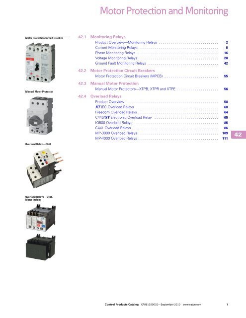
<strong>Motor</strong> <strong>Protection</strong> <strong>and</strong> <strong>Monitoring</strong><strong>Monitoring</strong> Relays42.1ECS Series CurrentWatch Current SwitchesECS Series CurrentWatch Current SwitchesECS SeriesProduct DescriptionThe CurrentWatch ECSSeries from Eaton’s electricalsector is a family of solidstateadjustable currentswitches, ideal for providingstatus information onelectrical equipment. TheECS is excellent for newinstallations, where theconductors run through thehousing, requiring no cutting.These switches are also idealfor retrofits, since split-coremodels can be opened to fitaround existing conductors.The current switch isaccurate, reliable <strong>and</strong> easyto install.The ECS can sensecontinuous currents from1 to 150A <strong>and</strong> does notrequire any supply voltage,as the power required isinduced from the monitoredconductor. The output is anon-polarity-sensitive solidstatecontact for switchingAC <strong>and</strong> DC circuits up to240 Vac/Vdc. This switch alsoincludes an LED indicatingtwo states: on <strong>and</strong> below trippoint, <strong>and</strong> above trip pointwith contacts energized. AllECS Series switches carry anunconditional five-yearwarranty.ReferenceRefer to PG08301004E, Sensing Solutions Catalog,Tab 7, section 7.2 for additional Product information.ECS Series CurrentWatchTab SectionApplication Description . . . . . . . . . . . . . . . . . . . . . . . . . . . . 7.2Product Selection . . . . . . . . . . . . . . . . . . . . . . . . . . . . . . . . . 7.2Accessories . . . . . . . . . . . . . . . . . . . . . . . . . . . . . . . . . . . . . 7.2Technical Data <strong>and</strong> Specifications . . . . . . . . . . . . . . . . . . . . 7.2Wiring Diagrams . . . . . . . . . . . . . . . . . . . . . . . . . . . . . . . . . 7.2Dimensions . . . . . . . . . . . . . . . . . . . . . . . . . . . . . . . . . . . . . 7.2ContentsDescriptionPageCurrent <strong>Monitoring</strong> RelaysECS Series CurrentWatch Current SwitchesECSJ Series CurrentWatch Current Switches . . . . . . . . 4D65 Current <strong>Monitoring</strong> Relays . . . . . . . . . . . . . . . . . . . 5Phase <strong>Monitoring</strong> Relays . . . . . . . . . . . . . . . . . . . . . . . . . . . 16Voltage <strong>Monitoring</strong> Relays . . . . . . . . . . . . . . . . . . . . . . . . . . 28Ground Fault <strong>Monitoring</strong> Relays . . . . . . . . . . . . . . . . . . . . . 42Any change in current can besensed with the ECS Series.A change in current mayindicate motor failure, beltloss/slippage or mechanicalfailure. Any of these eventscan cause the current to dropsignificantly, tripping theswitch <strong>and</strong> notifying thecontroller.St<strong>and</strong>ards <strong>and</strong> Certifications● UL Listed● cUL Listed● CE Certified424242424242424242424242424242424242424242424242424242424242Control Products Catalog CA08102001E—September 2010 www.eaton.com 3
42.1<strong>Motor</strong> <strong>Protection</strong> <strong>and</strong> <strong>Monitoring</strong><strong>Monitoring</strong> Relays424242424242424242424242424242424242424242424242424242424242ECSJ Series CurrentWatch Current SwitchesECSJ Series CurrentWatch Current SwitchesECSJ SeriesProduct DescriptionThe CurrentWatch ECSJSeries current operatedswitches from Eaton’selectrical sector provide thesame dependable indicationof status offered by theCurrentWatch ECS Series,but with the added benefit ofincreased setpoint precision.A choice of three, jumperselectableinput rangesallows the ECSJ Series to betailored to an application,providing more precisecontrol through improvedsetpoint resolution. Selfpowering,isolated solid-stateoutputs, 1–6A, 6–40A <strong>and</strong>40–200A input ranges, <strong>and</strong> achoice of split- or solid-coreenclosures are st<strong>and</strong>ard.For typical applications of theCurrentWatch ECSJ Series,see listing on this page.ReferenceRefer to PG08301004E, Sensing Solutions Catalog,Tab 7, section 7.3 for additional Product information.ECSJ Series CurrentWatchTab SectionApplication Description . . . . . . . . . . . . . . . . . . . . . . . . . . . . 7.3Product Selection . . . . . . . . . . . . . . . . . . . . . . . . . . . . . . . . 7.3Accessories . . . . . . . . . . . . . . . . . . . . . . . . . . . . . . . . . . . . . 7.3Technical Data <strong>and</strong> Specifications . . . . . . . . . . . . . . . . . . . . 7.3Wiring Diagrams . . . . . . . . . . . . . . . . . . . . . . . . . . . . . . . . . 7.3Dimensions . . . . . . . . . . . . . . . . . . . . . . . . . . . . . . . . . . . . . 7.3ContentsDescriptionPageCurrent <strong>Monitoring</strong> RelaysECS Series CurrentWatch Current Switches . . . . . . . . . 3ECSJ Series CurrentWatch Current SwitchesD65 Current <strong>Monitoring</strong> Relays . . . . . . . . . . . . . . . . . . . 5Phase <strong>Monitoring</strong> Relays . . . . . . . . . . . . . . . . . . . . . . . . . . 16Voltage <strong>Monitoring</strong> Relays . . . . . . . . . . . . . . . . . . . . . . . . . 28Ground Fault <strong>Monitoring</strong> Relays . . . . . . . . . . . . . . . . . . . . . 42Application DescriptionTypical Applications● Electronic Proof ofFlow—Current operatedswitches eliminate theneed for multiple pipe orduct penetrations <strong>and</strong> aremore reliable than electromechanicalpressure orflow switches● Conveyors—Detect jams<strong>and</strong> overloads● Lighting Circuits—Easierto install <strong>and</strong> moreaccurate than photocells●Fans, Pumps <strong>and</strong> HeatingElements—Fasterresponse than temperaturesensors● Critical <strong>Motor</strong>s● Ancillary EquipmentSt<strong>and</strong>ards <strong>and</strong> Certifications● UL Listed● cUL Listed● CE Certified● UL 508 IndustrialEquipment (USA <strong>and</strong>Canada)4 Control Products Catalog CA08102001E—September 2010 www.eaton.com
<strong>Motor</strong> <strong>Protection</strong> <strong>and</strong> <strong>Monitoring</strong><strong>Monitoring</strong> Relays42.1Current <strong>Monitoring</strong> RelaysProduct OverviewThe D65C Series Current<strong>Monitoring</strong> Relays monitor ACsingle-phase currents for overorundercurrent conditions inthree current ranges: 0.1–1A,0.5–5A <strong>and</strong> 1–10A. Anexternal current transformermay be used to extend theApplication DescriptionTypical Installation without External CTControlVoltageL1L256Current Monitor RelayTypical Installation with External CTControlVoltageL1L2MM3 4 1MMMM3 4 12568Current Monitor Relay28<strong>Motor</strong><strong>Motor</strong>range of the product. Aseparate 24V or 120 Vacinput (supply) voltageis required to power the unit.All versions are available in acompact plug-in case usingindustry st<strong>and</strong>ard 8- or 11-pinoctal sockets.ContentsDescriptionPageCurrent <strong>Monitoring</strong> RelaysECS Series CurrentWatch Current Switches . . . . . . . . . 3ECSJ Series CurrentWatch Current Switches . . . . . . . . 4D65 Current <strong>Monitoring</strong> RelaysProduct Selection Guide . . . . . . . . . . . . . . . . . . . . . . 6D65CE Series—St<strong>and</strong>ard Current Monitors . . . . . . . 7D65CH Series—Overcurrent Monitors . . . . . . . . . . . 10D65CL Series—Undercurrent Monitors . . . . . . . . . . 13Phase <strong>Monitoring</strong> Relays . . . . . . . . . . . . . . . . . . . . . . . . . . . 16Voltage <strong>Monitoring</strong> Relays . . . . . . . . . . . . . . . . . . . . . . . . . . 28Ground Fault <strong>Monitoring</strong> Relays . . . . . . . . . . . . . . . . . . . . . 42St<strong>and</strong>ards <strong>and</strong>Certifications●●●●CEcRUus listedUL listed RoHS compliantNotesWhen used with accompanying Eatonsocket. In addition to the above approvals, allplug-in products are also UL Listed whenused with the appropriate Eaton socket.424242424242424242424242424242424242424242424242424242424242Control Products Catalog CA08102001E—September 2010 www.eaton.com 5
42.1<strong>Motor</strong> <strong>Protection</strong> <strong>and</strong> <strong>Monitoring</strong><strong>Monitoring</strong> Relays424242424242424242424242424242424242424242424242424242424242Product Selection GuideSt<strong>and</strong>ardFixed time delay on bothpickup <strong>and</strong> dropout currentsettings.D65C St<strong>and</strong>ard FunctionPickupDropoutSeriesSetting Time Delay Setting Time DelayPageD65CEAdjustable (across Fixed 100 ms Fixed (–5% pickup) Fixed 100 ms 8D65CEKmonitored range)Adjustable(50–95% pickup)OvercurrentAdjustable time delay onpickup <strong>and</strong> fixed time delayon dropout current settings.D65C Overcurrent FunctionPickupDropoutSeriesSetting Time Delay Setting Time DelayPageD65CHAdjustable (across 0.1–10 sec adjustable Fixed (–5% pickup) Fixed 100 ms 11D65CHKmonitored range)Adjustable(50–95% pickup)UndercurrentFixed time delay on pickup<strong>and</strong> adjustable time delay ondropout current settings.D65C Undercurrent FunctionPickupDropoutSeriesSetting Time Delay Setting Time DelayD65CLFixed(+5% dropout)Fixed 100 ms NoteFixed time delay eliminates nuisance tripping due to short current surges or drops.Adjustable (acrossmonitored range)Page0.1–10 sec adjustable 146 Control Products Catalog CA08102001E—September 2010 www.eaton.com
<strong>Motor</strong> <strong>Protection</strong> <strong>and</strong> <strong>Monitoring</strong><strong>Monitoring</strong> Relays42.1D65CE Series—St<strong>and</strong>ard Current MonitorsD65CE Series—St<strong>and</strong>ard Current MonitorsProduct DescriptionFeaturesThe D65CE Series St<strong>and</strong>ardCurrent Monitors are used to● Monitors AC single-phasecurrentsdetect either an overcurrent● Three separate currentor undercurrent condition. monitoring ranges coveringThe pickup current setting is 0.1–10 amperesuser-adjustable within three● External CT can be used toranges (0.1–1A), (0.5–5A), orextend ranges(1–10A). The range can be●extended beyond 10A withAdjustable pickup settingthe use of an external currentwith either fixed ortransformer. Chooseadjustable dropout setting●between a fixed dropoutLED indicates output relaycurrent setting at 95% of the statusselected pickup setting or anadjustable dropout setting of50–95% of the selected● Choice of compact 8-pinSPDT or 11-pin DPDTplug-in casepickup setting. The relay will●energize when the monitored10A output contactsAC current is above thepickup setting, <strong>and</strong> will deenergizewhen the monitoredAC current is below thedropout setting. The timedelay on both pickup <strong>and</strong>dropout is fixed at 100 ms.Adjustable time delays areavailable with the D65CH <strong>and</strong>D65CL Series.ContentsDescriptionPageCurrent <strong>Monitoring</strong> RelaysECS Series CurrentWatch Current Switches . . . . . . . . . 3ECSJ Series CurrentWatch Current Switches . . . . . . . . 4D65 Current <strong>Monitoring</strong> RelaysProduct Selection Guide . . . . . . . . . . . . . . . . . . . . . . 6D65CE Series—St<strong>and</strong>ard Current MonitorsProduct Selection . . . . . . . . . . . . . . . . . . . . . . . . . 8Technical Data <strong>and</strong> Specifications . . . . . . . . . . . . 9Dimensions . . . . . . . . . . . . . . . . . . . . . . . . . . . . . 9D65CH Series—Overcurrent Monitors . . . . . . . . . . . 10D65CL Series—Undercurrent Monitors . . . . . . . . . . 13Phase <strong>Monitoring</strong> Relays . . . . . . . . . . . . . . . . . . . . . . . . . . . 16Voltage <strong>Monitoring</strong> Relays . . . . . . . . . . . . . . . . . . . . . . . . . . 28Ground Fault <strong>Monitoring</strong> Relays . . . . . . . . . . . . . . . . . . . . . 42St<strong>and</strong>ard Current <strong>Monitoring</strong>MonitoredCurrentInputPower(Voltage)RelayOutputPickupCurrentDropoutCurrentOnOffOnOff424242424242424242424242424242424242424242424242424242424242Control Products Catalog CA08102001E—September 2010 www.eaton.com 7
42.1<strong>Motor</strong> <strong>Protection</strong> <strong>and</strong> <strong>Monitoring</strong><strong>Monitoring</strong> Relays424242424242424242424242424242424242424242424242424242424242Product SelectionD65CE_D65CE_AccessoriesD65CE Series—St<strong>and</strong>ard Current Monitors, SPDT, 8-Pin Plug-InPickupSettingAdjustableDropoutSettingFixed(at 95% of pickup)Adjustable(from 50–95% of pickup)D65CE Series—St<strong>and</strong>ard Current Monitors, SPDT, 11-Pin Plug-InPickupSettingAdjustableDropoutSettingFixed(at 95% of pickup)Adjustable(from 50–95% of pickup)D65CE Current MonitorsSt<strong>and</strong>ardDescriptionPackCatalogNumber8-pin socket 10 D3PA211-pin socket 10 D3PA3-A2Hold-down spring 10 D65CHDSInput VoltageCurrent RangeMonitoredCatalogNumber24 Vac 0.1–1A D65CE1C01T0.5–5AD65CE1C5T1–10A D65CE1C10T120 Vac 0.1–1A D65CE1C01A0.5–5AD65CE1C5A1–10A D65CE1C10A24 Vac 0.1–1A D65CEK1C01T0.5–5AD65CEK1C5T1–10A D65CEK1C10T120 Vac 0.1–1A D65CEK1C01A0.5–5AD65CEK1C5A1–10A D65CEK1C10AInput VoltageCurrent RangeMonitoredCatalogNumber24 Vac 0.1–1A D65CE2C01T0.5–5AD65CE2C5T1–10A D65CE2C10T120 Vac 0.1–1A D65CE2C01A0.5–5AD65CE2C5A1–10A D65CE2C10A24 Vac 0.1–1A D65CEK2C01T0.5–5AD65CEK2C5T1–10A D65CEK2C10T120 Vac 0.1–1A D65CEK2C01A0.5–5AD65CEK2C5A1–10A D65CEK2C10A8 Control Products Catalog CA08102001E—September 2010 www.eaton.com
<strong>Motor</strong> <strong>Protection</strong> <strong>and</strong> <strong>Monitoring</strong><strong>Monitoring</strong> Relays42.1Technical Data <strong>and</strong> SpecificationsD65CE Series, St<strong>and</strong>ard Current MonitorsDescriptionInput voltage toleranceLoad (burden)Current settingsPickupDropoutTemperatureResponse timesPickupDropoutOutput contactsMechanical life<strong>Electrical</strong> lifeIndicator LEDResetMountingDimensionsApproximate Dimensions in Inches (mm)D65CE Series, St<strong>and</strong>ard Current Monitors2.4(60)D3PA2 Sockets1.7(43)SpecificationAC operation: +10/–15% of nominal voltage at 50/60 HzLess than 5 VA6–32 x 0.312 CombinationHead Screw <strong>and</strong> Pressure Clamping Plate(8 places)2.14(54.3)2.03(51.6)1.30(33.0)1.60(40.6)Max.Two 0.165(4.2) Dia.SlotsAdjustable throughout current range monitoredFixed at 95% of pickup setting for D65CEAdjustable from 50–95% of pickup setting for D65CEK–20° to 131°F (–28° to 55°C)100 ms100 ms10A resistive at 240 Vac/30 Vdc1/2 hp at 240 Vac (NO); 1/3 hp at 240 Vac (NC)10,000,000 operations100,000 operationsGreen when input voltage is applied;red when relay is energizedAutomaticRequires an 8- or 11-pin socketTolerances: ± 0.010± (0.25)Unless Otherwise Shown0.97(24.6)Max.2.9(74) 3.5(89)0.82 (20.8)0.58 (14.7)D65CEKOnlyD3PA3 Sockets6–32 x 0.312 CombinationHead Screw <strong>and</strong> Pressure Clamp(11 places)2.05(52.1)Max.2.06(52.3)2.33 (59.2)Max.Two 0.17(4.3) Dia.Holes0.13–0.16(3.2–4.0)Tolerances: ± 0.010± (0.25)Unless Otherwise ShownWiring DiagramsWiring for 8-Pin SocketMonitoredCurrentInputVoltage(L1) (L2)4 53 62 71 8Wiring for 11-Pin Socket(L1)0.97(24.6)MonitoredCurrent5 6 74 83 92 101 110.15 (3.8)0.58 (14.7)0.77 (19.6)(L2)424242424242424242424242424242424242424242424242424242424242Control Products Catalog CA08102001E—September 2010 www.eaton.com 9
42.1<strong>Motor</strong> <strong>Protection</strong> <strong>and</strong> <strong>Monitoring</strong><strong>Monitoring</strong> Relays424242424242424242424242424242424242424242424242424242424242D65CH Series—Overcurrent MonitorsD65CH Series—Overcurrent MonitorsFeaturesProduct DescriptionThe D65CH Series Overcurrent<strong>Monitoring</strong> Relays are usedto detect an overcurrentcondition. The pickup currentsetting is user-adjustablewithin one of three ranges asshown in product selectiontable. An external currenttransformer can be used toextend the range beyond10A. Users may select afixed dropout current setting(95% of the selected pick-upsetting) or an adjustable dropoutsetting (50–95% of theselected pickup setting). Therelay will energize when themonitored AC current isabove the pickup setting for aperiod longer than theadjustable time delay of0.1–10 seconds. This delayprevents nuisance trippingcaused by inrush currents. Itwill de-energize when themonitored AC current isbelow the dropout setting.●●●●●●●●Monitors AC single-phasecurrents for overcurrentconditionsThree separate currentmonitoring ranges covering0.1–10 amperesExternal CT can be used toextend rangesAdjustable pickup settingwith either fixed oradjustable dropout settingAdjustable time delay of0.1–10 seconds on pickupLED indicates output relaystatusChoice of compact SPDT(8-pin) or DPDT (11-pin)plug-in case10A output contactsContentsDescriptionPageCurrent <strong>Monitoring</strong> RelaysECS Series CurrentWatch Current Switches . . . . . . . . . 3ECSJ Series CurrentWatch Current Switches . . . . . . . . 4D65 Current <strong>Monitoring</strong> RelaysProduct Selection Guide . . . . . . . . . . . . . . . . . . . . . . 6D65CE Series—St<strong>and</strong>ard Current Monitors . . . . . . . 7D65CH Series—Overcurrent MonitorsProduct Selection . . . . . . . . . . . . . . . . . . . . . . . . . 11Technical Data <strong>and</strong> Specifications . . . . . . . . . . . . 12Dimensions . . . . . . . . . . . . . . . . . . . . . . . . . . . . . 12D65CL Series—Undercurrent Monitors . . . . . . . . . . 13Phase <strong>Monitoring</strong> Relays . . . . . . . . . . . . . . . . . . . . . . . . . . 16Voltage <strong>Monitoring</strong> Relays . . . . . . . . . . . . . . . . . . . . . . . . . 28Ground Fault <strong>Monitoring</strong> Relays . . . . . . . . . . . . . . . . . . . . . 42Overcurrent <strong>Monitoring</strong>MonitoredCurrentInputPower(Voltage)RelayOutputPickupCurrentDropoutCurrentOnOffOnOffTT10 Control Products Catalog CA08102001E—September 2010 www.eaton.com
<strong>Motor</strong> <strong>Protection</strong> <strong>and</strong> <strong>Monitoring</strong><strong>Monitoring</strong> Relays42.1Product SelectionD65CH_D65CH_AccessoriesD65CH Series—Overcurrent Monitors, SPDT, 8-Pin Plug-InPick-UpSettingAdjustableDrop-OutSettingFixed(at 95% of pickup)Adjustable(from 50–95% of pickup)D65CH Series—Overcurrent Monitors, SPDT, 11-Pin Plug-InPick-UpSettingAdjustableDrop-OutSettingFixed(at 95% of pickup)Adjustable(from 50–95% of pickup)D65CH Overcurrent MonitorsDescriptionSt<strong>and</strong>ardPackCatalogNumber8-pin socket 10 D3PA211-pin socket 10 D3PA3-A2Hold-down spring 10 D65CHDSInput VoltageCurrent RangeMonitoredCatalogNumber24 Vac 0.1–1A D65CH1C1T0.5–5AD65CH1C5T1–10A D65CH1C10T120 Vac 0.1–1A D65CH1C1A0.5–5AD65CH1C5A1–10A D65CH1C10A24 Vac 0.1–1A D65CHK1C1T0.5–5AD65CHK1C5T1–10A D65CHK1C10T120 Vac 0.1–1A D65CHK1C1A0.5–5AD65CHK1C5A1–10A D65CHK1C10AInput VoltageCurrent RangeMonitoredCatalogNumber24 Vac 0.1–1A D65CH2C1T0.5–5AD65CH2C5T1–10A D65CH2C10T120 Vac 0.1–1A D65CH2C1A0.5–5AD65CH2C5A1–10A D65CH2C10A24 Vac 0.1–1A D65CHK2C1T0.5–5AD65CHK2C5T1–10A D65CHK2C10T120 Vac 0.1–1A D65CHK2C1A0.5–5AD65CHK2C5A1–10A D65CHK2C10A424242424242424242424242424242424242424242424242424242424242Control Products Catalog CA08102001E—September 2010 www.eaton.com 11
42.1<strong>Motor</strong> <strong>Protection</strong> <strong>and</strong> <strong>Monitoring</strong><strong>Monitoring</strong> Relays424242424242424242424242424242424242424242424242424242424242Technical Data <strong>and</strong> SpecificationsD65CH Series, Overcurrent MonitorsDescriptionInput voltage toleranceLoad (burden)Current settingsPickupDropoutTemperatureResponse timesPickupDropoutOutput contactsMechanical life<strong>Electrical</strong> lifeIndicator LEDResetMountingDimensionsApproximate Dimensions in Inches (mm)D65CH Series, Overcurrent Monitors2.4(60)D3PA2 Sockets1.7(43)SpecificationAC operation: +10/–15% of nominal voltage at 50/60 HzLess than 5 VA6–32 x 0.312 CombinationHead Screw <strong>and</strong> Pressure Clamping Plate(8 places)2.14(54.3)2.03(51.6)1.30(33.0)1.60(40.6)Max.Two 0.165(4.2) Dia.SlotsAdjustable throughout current range monitoredFixed at 95% of pickup setting for D65CEAdjustable from 50–95% of pickup setting for D65CEK–20° to 131°F (–28° to 55°C)Adjustable 0.1–10 secondsFixed at 100 ms10A resistive at 240 Vac/30 Vdc1/2 hp at 240 Vac (NO); 1/3 hp at 240 Vac (NC)10,000,000 operations100,000 operationsGreen when input voltage is applied;red flashing when in time delay;red steady when relay is energizedAutomaticRequires an 8- or 11-pin socketTolerances: ± 0.010± (0.25)Unless Otherwise Shown0.97(24.6)Max.2.9(74) 3.5(89)0.82 (20.8)0.58 (14.7)D65CHKOnlyD3PA3 Sockets6–32 x 0.312 CombinationHead Screw <strong>and</strong> Pressure Clamp(11 places)2.05(52.1)Max.2.06(52.3)2.33 (59.2)Max.Two 0.17(4.3) Dia.Holes0.13–0.16(3.2–4.0)Tolerances: ± 0.010± (0.25)Unless Otherwise ShownWiring DiagramsWiring for 8-Pin SocketMonitoredCurrentInputVoltage(L1) (L2)4 53 62 71 8Wiring for 11-Pin Socket(L1)0.97(24.6)MonitoredCurrent5 6 74 83 92 101 110.15 (3.8)0.58 (14.7)0.77 (19.6)(L2)12 Control Products Catalog CA08102001E—September 2010 www.eaton.com
<strong>Motor</strong> <strong>Protection</strong> <strong>and</strong> <strong>Monitoring</strong><strong>Monitoring</strong> Relays42.1D65CL Series—Undercurrent MonitorsD65CL Series—Undercurrent MonitorsProduct DescriptionFeaturesThe D65CL Series isdesigned to detect anundercurrent condition. The● Monitors AC single-phasecurrents for undercurrentconditionsdropout current setting is● Three separate currentuser-adjustable within one of monitoring ranges coveringthree ranges as shown in the 0.1–10 amperesproduct selection table. An● External CT can be used toexternal current transformerextend rangescan be used to extend the●range beyond 10A. TheAdjustable dropout settingpickup current setting is fixedwith fixed pickup setting●at +5% of the selected dropoutsetting. The relay will0.1–10 seconds on dropoutAdjustable time delay ofenergize when the monitoredAC current is above the● LED indicates output relaystatuspickup setting. It will deenergizewhen the monitored (8-pin) or DPDT (11-pin)● Choice of compact SPDTAC current is below theplug-in casedropout setting for a period● 10A output contactslonger than the adjustabletime delay of 0.1–10seconds. This delay preventsnuisance tripping caused bymomentary line dips. Therelay will energize when thecurrent rises 5% above thedropout setting.ContentsDescriptionPageCurrent <strong>Monitoring</strong> RelaysECS Series CurrentWatch Current Switches . . . . . . . . . 3ECSJ Series CurrentWatch Current Switches . . . . . . . . 4D65 Current <strong>Monitoring</strong> RelaysProduct Selection Guide . . . . . . . . . . . . . . . . . . . . . . 6D65CE Series—St<strong>and</strong>ard Current Monitors . . . . . . . 7D65CH Series—Overcurrent Monitors . . . . . . . . . . . 10D65CL Series—Undercurrent MonitorsProduct Selection . . . . . . . . . . . . . . . . . . . . . . . . . 14Technical Data <strong>and</strong> Specifications . . . . . . . . . . . . 15Dimensions . . . . . . . . . . . . . . . . . . . . . . . . . . . . . 15Phase <strong>Monitoring</strong> Relays . . . . . . . . . . . . . . . . . . . . . . . . . . . 16Voltage <strong>Monitoring</strong> Relays . . . . . . . . . . . . . . . . . . . . . . . . . . 28Ground Fault <strong>Monitoring</strong> Relays . . . . . . . . . . . . . . . . . . . . . 42Undercurrent <strong>Monitoring</strong>MonitoredCurrentInputPower(Voltage)RelayOutputPickupCurrentDropoutCurrentOnOffOnOffT424242424242424242424242424242424242424242424242424242424242Control Products Catalog CA08102001E—September 2010 www.eaton.com 13
42.1<strong>Motor</strong> <strong>Protection</strong> <strong>and</strong> <strong>Monitoring</strong><strong>Monitoring</strong> Relays424242424242424242424242424242424242424242424242424242424242Product SelectionD65CL_D65CL_AccessoriesD65CL Series—Undercurrent Monitors, SPDT, 8-Pin Plug-InPickupSettingDropoutSettingD65CL Series—Undercurrent Monitors, SPDT, 11-Pin Plug-InD65CL Undercurrent MonitorsInput VoltageCurrent RangeMonitoredCatalogNumberFixed (at 5% of Dropout) Adjustable 24 Vac 0.1–1A D65CL1C1T0.5–5AD65CL1C5T1–10A D65CL1C10T120 Vac 0.1–1A D65CL1C1A0.5–5AD65CL1C5A1–10A D65CL1C10APickupSettingAdjustableDescriptionSt<strong>and</strong>ardPackDropoutSettingFixed(at 95% ofpickup)CatalogNumber8-pin socket 10 D3PA211-pin socket 10 D3PA3-A2Hold-down spring 10 D65CHDSInput VoltageCurrent RangeMonitoredCatalogNumber24 Vac 0.1–1A D65CL2C1T0.5–5AD65CL2C5T1–10A D65CL210T120 Vac 0.1–1A D65CL2C1A0.5–5AD65CL2C5A1–10A D65CL2C10A14 Control Products Catalog CA08102001E—September 2010 www.eaton.com
<strong>Motor</strong> <strong>Protection</strong> <strong>and</strong> <strong>Monitoring</strong><strong>Monitoring</strong> Relays42.1Technical Data <strong>and</strong> SpecificationsD65CL Series, Undercurrent MonitorsDescriptionInput voltage toleranceLoad (burden)Current settingsPickupDropoutTemperatureResponse timesPickupDropoutOutput contactsMechanical life<strong>Electrical</strong> lifeIndicator LEDResetMountingDimensionsApproximate Dimensions in Inches (mm)D65CL Series, Undercurrent Monitors2.4(60)D3PA2 Sockets1.7(43)SpecificationAC operation: +10/–15% of nominal voltage at 50/60 HzLess than 5 VA6–32 x 0.312 CombinationHead Screw <strong>and</strong> Pressure Clamping Plate(8 places)2.14(54.3)2.03(51.6)1.30(33.0)1.60(40.6)Max.Two 0.165(4.2) Dia.SlotsFixed at 5% above adjustable dropout settingAdjustable throughout current range monitored–20° to 131°F (–28° to 55°C)Fixed at 100 msAdjustable 0.1–10 seconds10A resistive at 240 Vac/30 Vdc1/2 hp at 240 Vac (NO); 1/3 hp at 240 Vac (NC)10,000,000 operations100,000 operationsGreen when input voltage is applied;red flashing when in time delay;red steady when relay is energizedAutomaticRequires an 8- or 11-pin socketTolerances: ± 0.010± (0.25)Unless Otherwise Shown0.97(24.6)Max.2.9(74) 3.5(89)0.82 (20.8)0.58 (14.7)D3PA3 Sockets6–32 x 0.312 CombinationHead Screw <strong>and</strong> Pressure Clamp(11 places)2.05(52.1)Max.2.06(52.3)2.33 (59.2)Max.Two 0.17(4.3) Dia.Holes0.13–0.16(3.2–4.0)Wiring DiagramsWiring for 8-Pin SocketMonitoredCurrentInputVoltage(L1) (L2)4 53 62 71 8Wiring for 11-Pin Socket(L1)Tolerances: ± 0.010± (0.25)Unless Otherwise Shown0.97(24.6)MonitoredCurrent5 6 74 83 92 101 110.15 (3.8)0.58 (14.7)0.77 (19.6)(L2)424242424242424242424242424242424242424242424242424242424242Control Products Catalog CA08102001E—September 2010 www.eaton.com 15
42.1<strong>Motor</strong> <strong>Protection</strong> <strong>and</strong> <strong>Monitoring</strong><strong>Monitoring</strong> Relays4242424242424242Phase <strong>Monitoring</strong> RelaysContentsDescriptionPageCurrent <strong>Monitoring</strong> Relays . . . . . . . . . . . . . . . . . . . . . . . . . 3Phase <strong>Monitoring</strong> RelaysSt<strong>and</strong>ards <strong>and</strong> Certifications . . . . . . . . . . . . . . . . . . . . . 17Product Selection Guide . . . . . . . . . . . . . . . . . . . . . . . . 17D65VMC Series—Phase Reversal . . . . . . . . . . . . . . . . . 18D65PLR Series—Phase Loss <strong>and</strong> Reversal . . . . . . . . . . 20D65PAR Series—Phase Loss, Reversal<strong>and</strong> Undervoltage . . . . . . . . . . . . . . . . . . . . . . . . . . . . 22D65VM Series—Phase Loss, Reversal, Imbalance<strong>and</strong> Under/Overvoltage . . . . . . . . . . . . . . . . . . . . . . . . 24Voltage <strong>Monitoring</strong> Relays . . . . . . . . . . . . . . . . . . . . . . . . . 28Ground Fault <strong>Monitoring</strong> Relays . . . . . . . . . . . . . . . . . . . . . 42424242424242424242424242424242424242Product OverviewThe D65 Series Phase<strong>Monitoring</strong> Relays provideprotection against prematureequipment failure caused byvoltage faults on three-phasesystems. All D65 phasemonitoring relays arecompatible with most wyeor delta systems. In wyesystems, a connection toneutral is not required. Phase<strong>Monitoring</strong> relays protectagainst single-phasingregardless of anyregenerative voltages.Application Description<strong>Protection</strong>Depending on the unitselected, it will protect threephaseequipment against:●●Phase Loss—total loss ofone or more of the threephases. Also known as“single phasing.” Typicallycaused by a blown fuse,broken wire or worn contact.This condition would result ina motor drawing locked rotorcurrent during startup. Inaddition, a three-phasemotor will continue to runafter losing a phase,resulting in possible motorburn-out.Phase Reversal—reversingany two of the three phaseswill cause a three-phasemotor to run in the oppositedirection. This may causedamage to driven machineryor injury to personnel. Thecondition usually occurs as aresult of mistakes madeduring routine maintenanceor when modifications aremade to the circuit.●●●Phase Imbalance—imbalance of a three-phasesystem occurs whensingle-phase loads areconnected such that one ortwo of the lines (phases)carry more or less of theload. This could causemotors to run attemperatures abovepublished ratings.Undervoltage—whenvoltage in all three lines ofa three-phase system dropsimultaneously.Overvoltage—whenvoltage in all three lines ofa three-phase systemincrease simultaneously.4242424216 Control Products Catalog CA08102001E—September 2010 www.eaton.com
<strong>Motor</strong> <strong>Protection</strong> <strong>and</strong> <strong>Monitoring</strong><strong>Monitoring</strong> Relays42.1Typical ConnectionsLine Side <strong>Monitoring</strong>With the relay connected before the motor starter, themotor can be started in the reverse direction. However, themotor is unprotected against phase failures between the relay<strong>and</strong> the motor.Line Side <strong>Monitoring</strong>St<strong>and</strong>ards <strong>and</strong> CertificationsD65VMC, D65PLR <strong>and</strong>D65PAR SeriesD65VMLP Series●●●L1L1L2L3StopStartMMMMInput Fuses2A Max.PhaseMonitorRelaycRUus listedRoHS recognizedCE marked (pending)(Pending)PhaseMonitorRelayProduct Selection GuideD65 Series—Product Family Selection●●●cRUus listedRoHS recognizedCE markedNoteIn addition to the above approvals, all plug-in products arealso UL Listed when used with the appropriate Eaton socket.MO/LL23Phase<strong>Motor</strong>Series Mounting Style Phase ReversalLoad Side <strong>Monitoring</strong>With the relay connected directly to the motor, the total feedlines are monitored. This connection should not be used withreversing motors.Load Side <strong>Monitoring</strong>D65VMLS Series● cULus listed● RoHS recognized●CE markedPhase Loss <strong>and</strong>Reversal Undervoltage Overvoltage Phase ImbalanceTime Delay onUndervoltageD65VMC Plug-in 3 — — — — —D65PLR Plug-in 3 3 — — — —D65PAR Plug-in 3 3 ✓ (adjustable) — — 50 ms fixedD65VMLP Plug-in 3 3 ✓ (adjustable) ✓ (fixed) 3 0.1–20 secD65VMLS Surface 3 3 ✓ (adjustable) ✓ (fixed) 3 0.1–20 secL1L1L2L3StopStartPhaseMonitor RelayMMMMO/LL23Phase<strong>Motor</strong>Input Fuses2A Max.PhaseMonitorRelay424242424242424242424242424242424242424242424242424242424242Control Products Catalog CA08102001E—September 2010 www.eaton.com 17
42.1<strong>Motor</strong> <strong>Protection</strong> <strong>and</strong> <strong>Monitoring</strong><strong>Monitoring</strong> Relays424242424242424242424242424242424242424242424242424242424242D65VMC Series—Phase ReversalD65VMC Series—Phase ReversalProduct DescriptionFeaturesThe D65VMC Series●<strong>Monitoring</strong> Relays provide reversalprotection against phase●reversal in a compact plug-indesign. One version will work systemson any three-phase system●from 208V to 480V(a separate 120V-only version●is also available). Thesedevices are designed to becompatible with most wye or●delta systems. In wyesystems, a connection to aneutral is not required.The relay is energized <strong>and</strong> theLED on when the sequenceis correct. Any fault will deenergizethe relay <strong>and</strong> turn offthe LED. Re-energization isautomatic upon correction ofthe fault condition.Protects against phaseOne version works on208–480V three-phaseLED indicates both normal<strong>and</strong> fault conditionsCompact plug-in caseutilizing industry-st<strong>and</strong>ard8-pin octal socket10A SPDT output contactsContentsDescriptionPageCurrent <strong>Monitoring</strong> Relays . . . . . . . . . . . . . . . . . . . . . . . . . 3Phase <strong>Monitoring</strong> RelaysProduct Selection Guide . . . . . . . . . . . . . . . . . . . . . . . . 17D65VMC Series—Phase ReversalProduct Selection . . . . . . . . . . . . . . . . . . . . . . . . . . . 19Technical Data <strong>and</strong> Specifications . . . . . . . . . . . . . . . 19Dimensions . . . . . . . . . . . . . . . . . . . . . . . . . . . . . . . . 19D65PLR Series—Phase Loss <strong>and</strong> Reversal . . . . . . . . . . 20D65PAR Series—Phase Loss, Reversal<strong>and</strong> Undervoltage . . . . . . . . . . . . . . . . . . . . . . . . . . . . 22D65VM Series—Phase Loss, Reversal, Imbalance<strong>and</strong> Under/Overvoltage . . . . . . . . . . . . . . . . . . . . . . . . 24Voltage <strong>Monitoring</strong> Relays . . . . . . . . . . . . . . . . . . . . . . . . . 28Ground Fault <strong>Monitoring</strong> Relays . . . . . . . . . . . . . . . . . . . . . 42St<strong>and</strong>ards <strong>and</strong> Certifications● cRUus● UL listed ● RoHS compliantNoteWhen used with appropriate Eatonsocket.18 Control Products Catalog CA08102001E—September 2010 www.eaton.com
<strong>Motor</strong> <strong>Protection</strong> <strong>and</strong> <strong>Monitoring</strong><strong>Monitoring</strong> Relays42.1Product SelectionD65VMC120AccessoriesTechnical Data <strong>and</strong> SpecificationsD65VMC Series, Phase ReversalMountingStyleD65VMC Series, Phase ReversalD65VMC Series, Phase ReversalDescriptionSpecificationPhase reversalUnit trips if sequence of the three phases is anything other than A-B-COutput contacts10A SPDT at 240 Vac, 1/3 hp at 240 Vac (NO), 1/6 hp at 240 Vac (NC)LifeFull load—100,000 operationsResponse timesOperate50 msRelease50 msLoad (burden)3 VATemperature–20° to 150°F (–28° to 65°C)Transient protection10,000 volts for 20 microsecondsMountingUses an 8-pin octal socket. Requires a 600V rated socket when used on system voltagesgreater than 300VIndicator LEDRed LED on when all conditions are normal, <strong>and</strong> off when a fault condition has occurredResetAutomatic upon correction of faultDimensionsApproximate Dimensions in Inches (mm)D65VMC Series, Phase Reversal2.40(60.0)1.70(43.0)Nominal Voltage50/60 HzNoteRequires a 600V rated socket when used on system voltages greater than 300V.CatalogNumberPlug-in 120V D65VMC120Plug-in 208–480V D65VMC480 DescriptionSt<strong>and</strong>ard PackCatalogNumber8-pin socket 10 D3PA2Hold-down spring 10 D65CHDS2.90(74.0)3.00(76.0)Wiring DiagramWiring for 8-Pin SocketØA ØB ØC4 53 62 71 8424242424242424242424242424242424242424242424242424242424242Control Products Catalog CA08102001E—September 2010 www.eaton.com 19
42.1<strong>Motor</strong> <strong>Protection</strong> <strong>and</strong> <strong>Monitoring</strong><strong>Monitoring</strong> Relays424242424242424242424242424242424242424242424242424242424242D65PLR Series—Phase Loss <strong>and</strong> ReversalD65PLR Series—Phase Loss <strong>and</strong> ReversalProduct DescriptionFeaturesThe D65PLR Series● Protects against phase loss<strong>Monitoring</strong> Relays provide <strong>and</strong> phase reversalprotection against phase loss● LED indicates both normal<strong>and</strong> phase reversal in a<strong>and</strong> fault conditionscompact plug-in design.● Compact plug-in caseThese devices are designedutilizing industry-st<strong>and</strong>ardto be compatible with most8-pin octal socketwye or delta systems. In wye●systems, a connection to a10A SPDT output contactsneutral is not required. Phasemonitoring relays protectagainst single-phasingregardless of anyregenerative voltages.The relay is energized <strong>and</strong> theLED on when all three phasesare present <strong>and</strong> in the correctsequence. Any fault willinstantaneously de-energizethe relay <strong>and</strong> turn off theLED. Re-energization isautomatic upon correction ofthe fault condition.ContentsDescriptionPageCurrent <strong>Monitoring</strong> Relays . . . . . . . . . . . . . . . . . . . . . . . . . 3Phase <strong>Monitoring</strong> RelaysProduct Selection Guide . . . . . . . . . . . . . . . . . . . . . . . . 17D65VMC Series—Phase Reversal . . . . . . . . . . . . . . . . . 18D65PLR Series—Phase Loss <strong>and</strong> ReversalProduct Selection . . . . . . . . . . . . . . . . . . . . . . . . . . . 21Technical Data <strong>and</strong> Specifications . . . . . . . . . . . . . . . 21Dimensions . . . . . . . . . . . . . . . . . . . . . . . . . . . . . . . . 21D65PAR Series—Phase Loss, Reversal<strong>and</strong> Undervoltage . . . . . . . . . . . . . . . . . . . . . . . . . . . . 22D65VM Series—Phase Loss, Reversal, Imbalance<strong>and</strong> Under/Overvoltage . . . . . . . . . . . . . . . . . . . . . . . . 24Voltage <strong>Monitoring</strong> Relays . . . . . . . . . . . . . . . . . . . . . . . . . 28Ground Fault <strong>Monitoring</strong> Relays . . . . . . . . . . . . . . . . . . . . . 42St<strong>and</strong>ards <strong>and</strong> Certifications● cRUus● UL listed ● RoHS compliantNoteWhen used with appropriate Eatonsocket.20 Control Products Catalog CA08102001E—September 2010 www.eaton.com
<strong>Motor</strong> <strong>Protection</strong> <strong>and</strong> <strong>Monitoring</strong><strong>Monitoring</strong> Relays42.1Product SelectionD65PLR120AccessoriesTechnical Data <strong>and</strong> SpecificationsD65PLR Series, Phase Loss <strong>and</strong> ReversalMountingStyleD65PLR Series, Phase Loss <strong>and</strong> ReversalD65PLR Series, Phase Loss <strong>and</strong> ReversalDescriptionSpecificationPhase lossUnit trips on loss of any Phase A, B or CPhase reversalUnit trips if sequence of the three phases is anything other than A-B-COutput contacts10A SPDT at 240 Vac, 1/3 hp at 240 Vac (NO), 1/6 hp at 240 Vac (NC)LifeFull load—100,000 operationsResponse timesOperate50 msRelease50 msLoad (burden)3 VATemperature–20° to 150°F (–28° to 65°C)Transient protection10,000 volts for 20 microsecondsMountingUses an 8-pin octal socket. Requires a 600V rated socket when used on system voltagesgreater than 300VIndicator LEDRed LED on when all conditions are normal, <strong>and</strong> off when a fault condition has occurredResetAutomatic upon correction of faultDimensionsApproximate Dimensions in Inches (mm)D65PLR Series, Phase Loss <strong>and</strong> Reversal2.40(60.0)1.70(43.0)Nominal Voltage50/60 HzNoteRequires a 600V rated socket when used on system voltages greater than 300V.CatalogNumberPlug-in 120V D65PLR120Plug-in 208V D65PLR208Plug-in 240V D65PLR240Plug-in 400V D65PLR400 Plug-in 480V D65PLR480 DescriptionSt<strong>and</strong>ard PackCatalogNumber8-pin socket 10 D3PA2Hold-down spring 10 D65CHDS2.90(74.0)3.00(76.0)Wiring DiagramWiring for 8-Pin SocketØA ØB ØC4 53 62 71 8424242424242424242424242424242424242424242424242424242424242Control Products Catalog CA08102001E—September 2010 www.eaton.com 21
42.1<strong>Motor</strong> <strong>Protection</strong> <strong>and</strong> <strong>Monitoring</strong><strong>Monitoring</strong> Relays424242424242424242424242424242424242424242424242424242424242D65PAR Series—Phase Loss, Reversal <strong>and</strong> UndervoltageD65PAR Series—Phase Loss, Reversal <strong>and</strong> UndervoltageProduct DescriptionFeaturesThe D65PAR Series● Protects against phase<strong>Monitoring</strong> Relays provide loss, phase reversal <strong>and</strong>protection against phase loss, undervoltagephase reversal <strong>and</strong>● Undervoltage setting isundervoltage in a compact adjustable from 75–95%plug-in design. These devices of nominalare designed to be● LED indicates both normalcompatible with most wye or<strong>and</strong> fault conditionsdelta systems. In wye●systems, a connection to aCompact plug-in caseneutral is not required. Phaseutilizing industry-st<strong>and</strong>ardmonitoring relays protect8-pin octal socket●against single-phasing10A SPDT output contactsregardless of anyregenerative voltages.The relay is energized <strong>and</strong> theLED on when all three phasesare present in the correctsequence at a voltage levelabove the undervoltagesetting. The undervoltagedrop-out can be set at 75–95% of operating voltage.Any fault will instantaneouslyde-energize the relay <strong>and</strong> turnoff the LED. Re-energizationis automatic upon correctionof the fault condition.ContentsDescriptionPageCurrent <strong>Monitoring</strong> Relays . . . . . . . . . . . . . . . . . . . . . . . . . 3Phase <strong>Monitoring</strong> RelaysProduct Selection Guide . . . . . . . . . . . . . . . . . . . . . . . . 17D65VMC Series—Phase Reversal . . . . . . . . . . . . . . . . . 18D65PLR Series—Phase Loss <strong>and</strong> Reversal . . . . . . . . . . 20D65PAR Series—Phase Loss, Reversal<strong>and</strong> Undervoltage . . . . . . . . . . . . . . . . . . . . . . . . . . . . 22Product Selection . . . . . . . . . . . . . . . . . . . . . . . . . . . 23Technical Data <strong>and</strong> Specifications . . . . . . . . . . . . . . . 23Dimensions . . . . . . . . . . . . . . . . . . . . . . . . . . . . . . . . 23D65VM Series—Phase Loss, Reversal, Imbalance<strong>and</strong> Under/Overvoltage . . . . . . . . . . . . . . . . . . . . . . . . 24Voltage <strong>Monitoring</strong> Relays . . . . . . . . . . . . . . . . . . . . . . . . . 28Ground Fault <strong>Monitoring</strong> Relays . . . . . . . . . . . . . . . . . . . . . 42St<strong>and</strong>ards <strong>and</strong> Certifications● cRUus● UL listed ● RoHS compliantNoteWhen used with appropriate Eatonsocket.22 Control Products Catalog CA08102001E—September 2010 www.eaton.com
<strong>Motor</strong> <strong>Protection</strong> <strong>and</strong> <strong>Monitoring</strong><strong>Monitoring</strong> Relays42.1Product SelectionD65PAR_AccessoriesTechnical Data <strong>and</strong> SpecificationsD65PAR Series, Phase Loss, Reversal <strong>and</strong> UndervoltageMountingStyleNominal Voltage60 HzD65PAR Series, Phase Loss, Reversal <strong>and</strong> UndervoltageCatalogDescriptionSt<strong>and</strong>ard PackNumberD65PAR Series, Phase Loss, Reversal <strong>and</strong> UndervoltageDescriptionSpecificationPhase lossUnit trips on loss of any Phase A, B or CPhase reversalUnit trips if sequence of the three phases is anything other than A-B-CUndervoltageAdjustable over a range per product selection table. Unit trips when the average of all three lines isless than the adjusted set point.Output contacts10A SPDT at 240 Vac, 1/3 hp at 240 Vac (NO), 1/6 hp at 240 Vac (NC)LifeFull load—100,000 operationsResponse timesOperate50 msRelease50 msLoad (burden)3 VATemperature–20° to 150°F (–28° to 65°C)Transient protection10,000 volts for 20 microsecondsMountingUses an 8-pin octal socket. Requires a 600V rated socket when used on system voltagesgreater than 300VIndicator LEDRed LED on when all conditions are normal, <strong>and</strong> off when a fault condition has occurredResetAutomatic upon correction of faultDimensionsApproximate Dimensions in Inches (mm)D65PAR Series, Phase Loss, Reversal <strong>and</strong> Undervoltage2.40(60.9)1.70(43.2)NoteRequires a 600V rated socket when used on system voltages greater than 300V.UndervoltageRangeCatalogNumberPlug-in 120V 90–115V D65PAR120Plug-in 208V 156–198V D65PAR208Plug-in 240V 180–230V D65PAR240Plug-in 400V 300–380V D65PAR400 Plug-in 480V 360–460V D65PAR480 8-pin socket 10 D3PA2Hold-down spring 10 D65CHDS2.90(73.7)3.50(88.9)Wiring DiagramWiring for 8-Pin SocketØA ØB ØC4 53 62 71 8424242424242424242424242424242424242424242424242424242424242Control Products Catalog CA08102001E—September 2010 www.eaton.com 23
42.1<strong>Motor</strong> <strong>Protection</strong> <strong>and</strong> <strong>Monitoring</strong><strong>Monitoring</strong> Relays424242424242424242424242424242424242424242424242424242424242D65VM Series—Phase Loss, Reversal, Imbalance <strong>and</strong> Under/OvervoltageContentsD65VM Series—Phase Loss, Reversal, Imbalance <strong>and</strong> Under/OvervoltageProduct DescriptionApplication DescriptionEaton’s D65 Phase<strong>Monitoring</strong> Relay protectsdistribution systemssupplying motor feeder orbranch circuits againstpremature equipment failurecaused by voltage faults onthree-phase systems—wyeor delta connected. Phasemonitoring relays protectagainst voltage imbalance <strong>and</strong>single-phasing regardless ofany regenerative voltages.The relay is energized whenthe phase sequence <strong>and</strong> allvoltages are correct. Any offive abnormal conditions(phase loss, phase reversal,overvoltage, undervoltageor phase imbalance) willde-energize the relay. Asst<strong>and</strong>ard, re-energizationis automatic upon correctionof the fault condition. TheD65 can also be wired formanual reset.Protective FunctionsThe D65 Series Relay makesseparate trip decisions basedon the status of the threephasevoltage inputs. Controlpower is derived from thethree-phase voltage inputs.Separate control power is notrequired. The device will tripin response to anycombination of the followingconditions:●Undervoltage—Whenvoltage in all three lines ofa three-phase systemdrops simultaneously.Undervoltage drop-out canbe set at 80–95% ofoperating voltage. Unittrips when the average ofall three lines is less thanthe adjusted set point for aperiod longer than theadjustable time delay dropout(0.1–20 seconds). Thistime delay eliminatesnuisance tripping causedby momentary voltagefluctuation.DescriptionPageCurrent <strong>Monitoring</strong> Relays . . . . . . . . . . . . . . . . . . . . . . . . . 3Phase <strong>Monitoring</strong> RelaysProduct Selection Guide . . . . . . . . . . . . . . . . . . . . . . . . 17D65VMC Series—Phase Reversal . . . . . . . . . . . . . . . . . 18D65PLR Series—Phase Loss <strong>and</strong> Reversal . . . . . . . . . . 20D65PAR Series—Phase Loss, Reversal<strong>and</strong> Undervoltage . . . . . . . . . . . . . . . . . . . . . . . . . . . . 22D65VM Series—Phase Loss, Reversal, Imbalance<strong>and</strong> Under/OvervoltageFeatures . . . . . . . . . . . . . . . . . . . . . . . . . . . . . . . . . . 25Product Selection . . . . . . . . . . . . . . . . . . . . . . . . . . . 26Technical Data <strong>and</strong> Specifications . . . . . . . . . . . . . . . 26Dimensions . . . . . . . . . . . . . . . . . . . . . . . . . . . . . . . . 27Voltage <strong>Monitoring</strong> Relays . . . . . . . . . . . . . . . . . . . . . . . . . 28Ground Fault <strong>Monitoring</strong> Relays . . . . . . . . . . . . . . . . . . . . . 42●●Overvoltage—Fixed at110% of nominal, unit tripswhen the average of allthree lines is greater thanthe fixed set point for aperiod longer than the timedelay drop-out.Phase Imbalance—Imbalance of a three-phasesystem occurs whensingle-phase loads areconnected such that one ortwo of the lines (phases)carry more or less of theload. This could causemotors to run attemperatures abovepublished ratings. Unit tripswhen any one of the threelines is more than theadjusted set point belowthe average of all threelines. The percent phaseimbalance is adjustablefrom 2–10% <strong>and</strong> also has aDisable setting forapplications where poorvoltage conditions couldcause nuisance tripping.●●Phase Loss (Single-Phasing)—Total loss ofone or more of the threephases. Typically causedby a blown fuse, brokenwire or worn contact. Thiscondition would result in amotor drawing locked rotorcurrent during start-up. Inaddition, a three-phasemotor will continue to runafter losing a phase,resulting in potential motorburn-out. Unit trips on lossof any phase.Phase Reversal—Reversing any two of thethree phases will cause athree-phase motor to run inthe opposite direction. Thismay cause damage tomachinery or injury topersonnel. Unit trips ifrotation (sequence) of thethree phases is anythingother than A-B-C.24 Control Products Catalog CA08102001E—September 2010 www.eaton.com
<strong>Motor</strong> <strong>Protection</strong> <strong>and</strong> <strong>Monitoring</strong><strong>Monitoring</strong> Relays42.1Typical ConnectionsLine Side <strong>Monitoring</strong>L1L1L2L3STOPSTARTMMMMInput Fuses(Recommended)Voltage 2A Max.MonitorRelayWith the relay connected before the motor starter, the motorcan be started in the reverse direction. However, the motoris unprotected against phase failures between the relay <strong>and</strong>the motor.Features●Universal voltage range of208–480V provides theflexibility to cover a varietyof applications (120V <strong>and</strong>600V units also available)●Automatic or manual resetafter the fault condition iscorrected●Multi-color LED indicatesnormal condition <strong>and</strong>defines fault type forsimpler troubleshootingOperationThe D65 provides protectionagainst premature equipmentfailure caused by voltagefaults on three-phasesystems. The D65 isdesigned to be compatiblewith most wye or deltasystems. In wye systems, aconnection to a neutral is notrequired. D65 Phase<strong>Monitoring</strong> Relays protectagainst imbalanced voltagesor single-phasing regardlessof any regenerative voltages.The relay is energized whenthe phase sequence <strong>and</strong> allvoltages are correct. Any oneof five fault conditions will deenergizethe relay. Reenergizationis automaticupon correction of the faultcondition.MVoltage MonitorRelay●O/LL23Phase<strong>Motor</strong>D65VMLS can be eithermounted directly on35 mm DIN rail with noadditional parts or to aback-panel with twoscrews. No socketrequired. D65VMLP willplug into D3PA2 socket<strong>and</strong> mount on 35 mmDIN railManual reset is available ifa NC switch is wired to theappropriate terminals. Amulti-color LED indicatesnormal condition <strong>and</strong> alsoprovides specific faultindication to simplifytroubleshooting. The percentphase imbalance is adjustablefrom 2–10%, <strong>and</strong> theundervoltage drop-out can beset at 80–95% of operatingvoltage. The adjustable timedelay drop-out onundervoltage (0.1–20 sec.)eliminates nuisance trippingcaused by momentaryvoltage fluctuations.Load Side <strong>Monitoring</strong>L1L1L2L3With the relay connected directly to the motor, the total feedlines are monitored. This connection should not be used withreversing motors.●●STOPSmall, compact sizeUser-adjustable settingsinclude nominal voltage,percent phase imbalance,undervoltage drop-out,time delay on undervoltage<strong>and</strong> time delay on restartafter faultLED OperationLED StatusGreen steadyGreen flashingRed steadyRed flashingAmber steadyAmber flashingAlternating green/redAlternating red/amberSTARTVoltage MonitorRelayMMMMO/LL23Phase<strong>Motor</strong>Input Fuses(Recommended)2A Max.VoltageMonitorRelayIndicatorNormal/relay ONPower-up/restart delayImbalanceUndervoltage/overvoltageReversalLossUndervoltage/overvoltage trip pendingNominal voltage set error424242424242424242424242424242424242424242424242424242424242Control Products Catalog CA08102001E—September 2010 www.eaton.com 25
42.1<strong>Motor</strong> <strong>Protection</strong> <strong>and</strong> <strong>Monitoring</strong><strong>Monitoring</strong> Relays424242424242424242424242424242424242424242424242424242424242St<strong>and</strong>ards <strong>and</strong> Certifications●CE (Low Voltage + EMCDirective EN60947-5-1)●cULus listed(D65VMLS only)Product SelectionD65VM_Technical Data <strong>and</strong> Specifications●●cRUus(D65VMLP only)RoHS compliantD65VM Series—Phase Loss, Reversal, Imbalance <strong>and</strong>Under/Overvoltage Mounting StyleOperating Voltage50/60 Hz●UL Listed D65VM Series—Phase Loss, Reversal, Imbalance <strong>and</strong> Under/OvervoltageDescriptionSpecificationNominal voltages 120V, 208–480V, 575V(50–60 Hz)ConnectionsThree-wire wye or deltaOutput contactsFor D65VMLSSPDT <strong>and</strong> SPNC (surface mount version only)NO: 10A resistive at 240 Vac/30 Vdc, 1/2 hp at 240 VacNC: 10A resistive at 240 Vac/30 Vdc, 1/3 hp at 240 VacFor D65VMLPSPDT:10A Resistive at 240 Vac/30 Vdc; 1/2 hp at 120/240 VacDielectric1000V + (2 * nominal voltage rating) between input terminals <strong>and</strong> case or active circuitryOperating temp.–20° to 150°F (–28° to 65°C)Response timesPower up1–300 seconds adjustableRestart after fault 1–300 seconds adjustableDropout due to fault 100 ms fixed on phase loss <strong>and</strong> phase reversal;2 seconds fixed on phase imbalance;0.1–20 sec. adjustable on undervoltage only; inverse time curve for overvoltageMechanical life10,000,000 operations<strong>Electrical</strong> life100,000 operationsPower consumption 3 VANet weight10.3 oz. (292g) D65VMLS6.4 oz. (181g) D65VMLPHysteresis 2–3%CatalogNumberSurface-mount120VD65VMLS120(DIN rail or panel)208–480V D65VMLS480600VD65VMLS600Plug-in120VD65VMLP120(DIN rail)208–480V D65VMLP480 8-pin socket — D3PA28-pin IP20 rated socket — D3PA6NotesWhen used with accompanying Eaton Socket (D65VMLP only).Additional models available. Please visit our Web site for the latest offering.Requires a 600V-rated socket when used on system voltages greater than 300V. The D3PA2 socket is rated 10A, 600V.26 Control Products Catalog CA08102001E—September 2010 www.eaton.com
<strong>Motor</strong> <strong>Protection</strong> <strong>and</strong> <strong>Monitoring</strong><strong>Monitoring</strong> Relays42.1Wiring DiagramsSurface-Mount <strong>and</strong> Plug-InØA ØB ØCA B C11 2112 14 M1M222Manual ResetDimensionsØA ØB ØC4 53 62 71 8ManualResetApproximate Dimensions in Inches (mm)Surface-Mount <strong>and</strong> Plug-In2.70 2.40(68.6) (60.1)2.40(60.1)1.40(35.6)1.80 (45.7)1.70 (43.2)0.20 (50.8) Mounting Holes – 2 Places4.40 (111.8)4.50 (114.3)2.90 (73.7)3.00 (76.2)424242424242424242424242424242424242424242424242424242424242Control Products Catalog CA08102001E—September 2010 www.eaton.com 27
42.1<strong>Motor</strong> <strong>Protection</strong> <strong>and</strong> <strong>Monitoring</strong><strong>Monitoring</strong> Relays4242424242424242Voltage <strong>Monitoring</strong> RelaysContentsDescriptionPageCurrent <strong>Monitoring</strong> Relays . . . . . . . . . . . . . . . . . . . . . . . . . 3Phase <strong>Monitoring</strong> Relays . . . . . . . . . . . . . . . . . . . . . . . . . . 16Voltage <strong>Monitoring</strong> RelaysProduct Selection Guide . . . . . . . . . . . . . . . . . . . . . . . . 29D65VMRP <strong>and</strong> D65VMKP Over/Undervoltage Relays(Fixed Time Delay) . . . . . . . . . . . . . . . . . . . . . . . . . . . . 30D65VAP <strong>and</strong> D65VAKP Over/Undervoltage Relays . . . . . 33D65VWP <strong>and</strong> D65VWKP Voltage B<strong>and</strong> Relays . . . . . . . 36VSR Series—Solid-<strong>State</strong>, Single-PhaseVoltage Sensing . . . . . . . . . . . . . . . . . . . . . . . . . . . . . . 39Ground Fault <strong>Monitoring</strong> Relays . . . . . . . . . . . . . . . . . . . . . 42424242424242424242424242424242Product OverviewVoltage <strong>Monitoring</strong> Relaysmonitor either AC singlephase(50/60 Hz) or DCvoltages to protectequipment against voltagefault conditions. No separatesupply (input) voltage isrequired. All versions areavailable in a compact plug-incase using an 8-pin octalsocket.There are two styles ofvoltage monitoring relays:●●Over/Undervoltage RelaysVoltage B<strong>and</strong> RelaysOver/Undervoltage RelaysOver/Undervoltage Relaysprovide protection toequipment where either anover- or undervoltagecondition is potentiallydamaging. Each relay can beused as either an overvoltageor an undervoltage relay,depending on the outputcontact used. When used asan undervoltage relay, itprovides protection toequipment that is required tooperate above a minimumvoltage. When used as anovervoltage relay, it protectsequipment against excessivevoltage conditions. Over/undervoltage relays aredesigned to operate whenthe operating voltage reachesa preset value <strong>and</strong> drop outwhen the operating voltagedrops to a level below thepreset value.Voltage B<strong>and</strong> RelaysVoltage B<strong>and</strong> Relays provideprotection to equipment thatis required to operate withinan upper <strong>and</strong> lower voltagelimit. As long as the operatingvoltage remains within anover- <strong>and</strong> undervoltage range,the internal relay staysenergized. If the operatingvoltage falls outside thisrange, the relay will drop out.St<strong>and</strong>ards <strong>and</strong>Certifications●●●●CEcRUus listedUL listed RoHS recognizedNoteWhen used with accompanying Eatonsocket.4242424242424228 Control Products Catalog CA08102001E—September 2010 www.eaton.com
<strong>Motor</strong> <strong>Protection</strong> <strong>and</strong> <strong>Monitoring</strong><strong>Monitoring</strong> Relays42.1Product Selection GuideD65V Product Family Selection—Over/Undervoltage RelaysSeriesPickupVoltageDropoutVoltageD65V Product Family Selection—Voltage B<strong>and</strong> RelaysNoteFixed time delay eliminates nuisance tripping due to short voltage surges or drops.Time DelayDropoutFixed Time Delay forOver/Undervoltage RelaysD65VMP AdjustableFixed at 95% of pickup Fixed 500 ms Page 31 —D65VMKP85–115% nominalAdjustable 75–95% of pickup Page 31 —D65VAP Fixed at 95% of pickup Adjustable 0.5–10 seconds — Page 34D65VAKP Adjustable 75–95% of pickup — Page 34SeriesPickupVoltageDropoutVoltageTime DelayDropoutD65VWP AdjustableAdjustable 75–100% of nominal Fixed 500 ms Page 37D65VWKP100–125% nominalAdjustable 0.5–10 seconds Page 37Voltage B<strong>and</strong> RelaysAdjustable Time DelayOver/Undervoltage Relays424242424242424242424242424242424242424242424242424242424242Control Products Catalog CA08102001E—September 2010 www.eaton.com 29
42.1<strong>Motor</strong> <strong>Protection</strong> <strong>and</strong> <strong>Monitoring</strong><strong>Monitoring</strong> Relays424242424242424242424242424242424242424242424242424242424242D65VMRP <strong>and</strong> D65VMKP—Fixed Time Delay Over/Undervoltage RelaysD65VMRP <strong>and</strong> D65VMKP Over/Undervoltage Relays(Fixed Time Delay)Product DescriptionThe D65VMRP <strong>and</strong>D65VMKP Over/Undervoltage Relays provideprotection to equipmentwhere either an over- orundercurrent condition ispotentially damaging. Theyare designed to operatewhen the operating voltagereaches a preset value <strong>and</strong>drop out when the operatingvoltage drops to a level belowthe preset value.The pickup voltage settingis user-adjustable from85–115% of the nominalvoltage rating. As st<strong>and</strong>ard,the D65VMRP Series has adropout voltage setting fixedat 95% of the pickup voltagesetting. An adjustable dropoutsetting of 75–95% of thepickup setting is available onthe D65VMKP Series. Therelay energizes when themonitored voltage is abovethe pickup setting. The relayde-energizes when themonitored voltage is belowthe dropout setting for aperiod longer than the dropouttime delay, which is fixedat 500 ms. An adjustable timedelay on dropout of0.5–10 seconds is available.Application DescriptionEach relay can be used aseither an overvoltage or anundervoltage relay,depending on the outputcontact used.Overvoltage RelayProvides protection toequipment that cannot h<strong>and</strong>leexcess voltages. Uses anormally closed contact (NC).As long as the monitoredvoltage remains below themaximum voltage theequipment can withst<strong>and</strong>(pickup setting), the relayremains energized <strong>and</strong> theNC contact remains closed,keeping the load energized. Ifthe operating voltageincreases beyond themaximum rating of theequipment, the relayenergizes <strong>and</strong> the NC contactopens, turning off the load.When the voltage falls belowthe dropout settings(hysteresis), the relay deenergizes<strong>and</strong> the NC contactre-closes, turning on the load.ContentsDescriptionPageCurrent <strong>Monitoring</strong> Relays . . . . . . . . . . . . . . . . . . . . . . . . . 3Phase <strong>Monitoring</strong> Relays . . . . . . . . . . . . . . . . . . . . . . . . . . 16Voltage <strong>Monitoring</strong> RelaysProduct Selection Guide . . . . . . . . . . . . . . . . . . . . . . . . 29D65VMRP <strong>and</strong> D65VMKP Over/Undervoltage Relays(Fixed Time Delay)Product Selection . . . . . . . . . . . . . . . . . . . . . . . . . . . 31Technical Data <strong>and</strong> Specifications . . . . . . . . . . . . . . . 32Dimensions . . . . . . . . . . . . . . . . . . . . . . . . . . . . . . . . 32D65VAP <strong>and</strong> D65VAKP Over/Undervoltage Relays . . . . . 33D65VWP <strong>and</strong> D65VWKP Voltage B<strong>and</strong> Relays . . . . . . . 36VSR Series—Solid-<strong>State</strong>, Single-PhaseVoltage Sensing . . . . . . . . . . . . . . . . . . . . . . . . . . . . . . 39Ground Fault <strong>Monitoring</strong> Relays . . . . . . . . . . . . . . . . . . . . . 42Undervoltage RelayProvides protection toequipment that is required tooperate above a certainminimum voltage. Uses anormally open contact (NO).As long as the monitoredvoltage is above theminimum value required(pickup setting), the relay willenergize <strong>and</strong> the NO contactcloses, turning on the load. Ifthe voltage drops below thedropout setting (the minimumvoltage required minushysteresis), the relay will deenergize<strong>and</strong> the NO contactwill re-open, turning off theload.Features● Monitors AC single-phase<strong>and</strong> DC voltages● Wide range of useradjustablepickup <strong>and</strong>dropout settings● Fixed time delay ondropout of 500 ms● LED indicates output relaystatus● Compact plug-in caseusing industry st<strong>and</strong>ard8-pin socket● 10A DPDT output contactsFixed Time Delay Over/Undervoltage Current <strong>Monitoring</strong>MonitoredVoltageRelayOutputPickupVoltageDropoutVoltageOnOffTT30 Control Products Catalog CA08102001E—September 2010 www.eaton.com
<strong>Motor</strong> <strong>Protection</strong> <strong>and</strong> <strong>Monitoring</strong><strong>Monitoring</strong> Relays42.1Product SelectionD65VM_D65VM_AccessoriesD65VMP <strong>and</strong> D65VMKP Series—Over/Undervoltage Relay ,Adjustable Pickup, Fixed Dropout Settings NominalVoltageVoltage RangePickupD65VMP <strong>and</strong> D65VMKP Series—Over/Undervoltage Relay ,Adjustable Pickup <strong>and</strong> Dropout Settings D65VMP <strong>and</strong> D65VMKP Series—Over/Undervoltage RelaysDropoutNotesTime delay on dropout fixed at 500 ms.Dropout voltage is fixed at 95% of the adjusted pickup setting.Dropout voltage is adjustable from 75–95% of the adjusted pickup setting.CatalogNumber24 Vac 21–27 Vac 20–26 Vac D65VMRPT120 Vac 102–138 Vac 97–131 Vac D65VMRPA12 Vdc 10–14 Vdc 9–13 Vdc D65VMRPR124 Vdc 21–27 Vdc 20–26 Vdc D65VMRPT148 Vdc 41–55 Vdc 39–52 Vdc D65VMRPW1110 Vdc 94–126 Vdc 89–121 Vdc D65VMRPA1NominalVoltageVoltage RangePickupDropoutCatalogNumber24 Vac 21–27 Vac 16–26 Vac D65VMKPT120 Vac 102–138 Vac 77–131 Vac D65VMKPA12 Vdc 10–14 Vdc 8–13 Vdc D65VMKPR124 Vdc 21–27 Vdc 16–26 Vdc D65VMKPT148 Vdc 41–55 Vdc 32–52 Vdc D65VMKPW1110 Vdc 94–126 Vdc 71–121 Vdc D65VMKPA1DescriptionSt<strong>and</strong>ardPackCatalogNumber8-pin socket 10 D3PA2Hold-down spring 10 D65CHDS424242424242424242424242424242424242424242424242424242424242Control Products Catalog CA08102001E—September 2010 www.eaton.com 31
42.1<strong>Motor</strong> <strong>Protection</strong> <strong>and</strong> <strong>Monitoring</strong><strong>Monitoring</strong> Relays424242424242424242424242424242424242424242424242424242424242Technical Data <strong>and</strong> SpecificationsD65V Series—Fixed <strong>and</strong> Adjustable Time Delay Over/Undervoltage RelaysD65VMP, D65VMKP, D65VAP <strong>and</strong> D65VAKP Series, Over/Undervoltage RelaysDescriptionSpecificationVoltage tolerance+25%/–50% of nominal voltage; AC voltages are 50/60 HzNo supply (input) voltage is requiredLoad (burden)Less than 3 VACurrent settingsPickupAdjustable from 85–115% of nominal voltageDropoutFixed at 95% of the pickup setting for D65VMP <strong>and</strong> D65VAPAdjustable from 75–95% of the pickup setting for D65VMKP <strong>and</strong> D65VAKPTemperature–20° to 131°F (–28° to 55°C)Response timesPickup500 msDropoutFixed 500 ms for D65VMP <strong>and</strong> D65VMKPAdjustable 0.5–10 seconds for D65VAP <strong>and</strong> D65VAKPOutput contacts10A Resistive at 240 Vac/30 Vdc, 1/2 hp at 240 Vac (NO), 1/3 hp at 240 Vac (NC)Mechanical life10,000,000 operations<strong>Electrical</strong> life100,000 operationsIndicator LEDRed steady when relay is energized;green when relay is OFFTransient protection10,000 volts for 20 microsecondsResetAutomaticMountingRequires an 8-pin socketWiring DiagramWiring for 8-Pin Socket(DC)+L14 53 62 71 8MonitoredVoltage(DC)−L2DimensionsApproximate Dimensions in Inches (mm)D65V Series—Fixed <strong>and</strong> Adjustable Time Delay Over/Undervoltage Relays2.4(60)1.7(43)2.9(74) 3.5(89)D65VMKP <strong>and</strong>D65VAKP Only32 Control Products Catalog CA08102001E—September 2010 www.eaton.com
<strong>Motor</strong> <strong>Protection</strong> <strong>and</strong> <strong>Monitoring</strong><strong>Monitoring</strong> Relays42.1D65VAP & D65VAKP—Adjustable Time Delay Over/Undervoltage RelaysD65VAP <strong>and</strong> D65VAKP Over/Undervoltage Relays(Adjustable Time Delay)Product DescriptionThe D65VAP <strong>and</strong> D65VAKPOver/Undervoltage Relaysprovide protection toequipment where either anover- or undercurrentcondition is potentiallydamaging. They are designedto operate when theoperating voltage reaches apreset value <strong>and</strong> drop outwhen the operating voltagedrops to a level below thepreset value.The pickup voltage setting isuser-adjustable from 85–115% of the nominal voltagerating. As st<strong>and</strong>ard, theD65VAP Series has a dropoutvoltage setting fixed at 95%of the pickup voltage setting.An adjustable dropout settingof 75–95% of the pickupsetting is available on theD65VAKP Series. The relayenergizes when themonitored voltage is abovethe pickup setting. The relayde-energizes when themonitored voltage is belowthe dropout setting for aperiod longer than thedropout time delay, which isadjustable from 0.5–10seconds. A fixed time delayof 500 ms is available withthe D65VMP Series.Application DescriptionEach relay can be used aseither an overvoltage or anundervoltage relay,depending on the outputcontact used.Overvoltage RelayProvides protection toequipment that cannot h<strong>and</strong>leexcess voltages. Uses anormally closed contact (NC).As long as the monitoredvoltage remains below themaximum voltage theequipment can withst<strong>and</strong>(pickup setting), the relayremains energized <strong>and</strong> theNC contact remains closed,keeping the load energized.If the operating voltageincreases beyond themaximum rating of theequipment, the relayenergizes <strong>and</strong> the NC contactopens, turning off the load.When the voltage falls belowthe dropout settings(hysteresis), the relay deenergizes<strong>and</strong> the NC contactre-closes, turning on the load.ContentsDescriptionPageCurrent <strong>Monitoring</strong> Relays . . . . . . . . . . . . . . . . . . . . . . . . . . 3Phase <strong>Monitoring</strong> Relays . . . . . . . . . . . . . . . . . . . . . . . . . . . 16Voltage <strong>Monitoring</strong> RelaysProduct Selection Guide . . . . . . . . . . . . . . . . . . . . . . . . . 29D65VMRP <strong>and</strong> D65VMKP Over/Undervoltage Relays(Fixed Time Delay) . . . . . . . . . . . . . . . . . . . . . . . . . . . . 30D65VAP <strong>and</strong> D65VAKP Over/Undervoltage Relays(Adjustable Time Delay)Product Selection . . . . . . . . . . . . . . . . . . . . . . . . . . . 34Technical Data <strong>and</strong> Specifications . . . . . . . . . . . . . . . 35Dimensions . . . . . . . . . . . . . . . . . . . . . . . . . . . . . . . . 35D65VWP <strong>and</strong> D65VWKP Voltage B<strong>and</strong> Relays . . . . . . . 36VSR Series—Solid-<strong>State</strong>, Single-PhaseVoltage Sensing . . . . . . . . . . . . . . . . . . . . . . . . . . . . . . 39Ground Fault <strong>Monitoring</strong> Relays . . . . . . . . . . . . . . . . . . . . . 42Undervoltage RelayProvides protection toequipment that is required tooperate above a certainminimum voltage. Uses anormally open contact (NO).As long as the monitoredvoltage is above the minimumvalue required (pickup setting),the relay will energize <strong>and</strong> theNO contact closes, turning onthe load. If the voltage dropsbelow the dropout setting(the minimum voltagerequired minus hysteresis),the relay will de-energize <strong>and</strong>the NO contact will re-open,turning off the load.Features● Monitors AC single-phase<strong>and</strong> DC voltages● Wide range of useradjustablepickup <strong>and</strong>dropout settings● Adjustable time delay ondropout of 0.5–10 seconds● LED indicates outputrelay status● Compact plug-in caseusing industry st<strong>and</strong>ard8-pin socket● 10A DPDT output contactsAdjustable Time Delay Over/Undervoltage Current <strong>Monitoring</strong>MonitoredVoltageRelayOutputPickupVoltageDropoutVoltageOnOffTT424242424242424242424242424242424242424242424242424242424242Control Products Catalog CA08102001E—September 2010 www.eaton.com 33
42.1<strong>Motor</strong> <strong>Protection</strong> <strong>and</strong> <strong>Monitoring</strong><strong>Monitoring</strong> Relays424242424242424242424242424242424242424242424242424242424242Product SelectionD65VA_D65VA_AccessoriesD65VAP <strong>and</strong> D65VAKP Series—Over/Undervoltage Relay ,Adjustable Pickup, Fixed Dropout Settings NominalVoltageVoltage RangePickupD65VAP <strong>and</strong> D65VAKP Series—Over/Undervoltage Relay ,Adjustable Pickup <strong>and</strong> Dropout Settings D65VMP <strong>and</strong> D65VMKP Series—Over/Undervoltage RelaysDropoutNotesTime delay on dropout fixed at 500 ms.Dropout voltage is fixed at 95% of the adjusted pickup setting.Dropout voltage is adjustable from 75–95% of the adjusted pickup setting.CatalogNumber24 Vac 21–27 Vac 20–26 Vac D65VAPT120 Vac 102–138 Vac 97–131 Vac D65VAPA12 Vdc 10–14 Vdc 9–13 Vdc D65VAPR124 Vdc 21–27 Vdc 20–26 Vdc D65VAPT148 Vdc 41–55 Vdc 39–53 Vdc D65VAPW1110 Vdc 94–126 Vdc 89–121 Vdc D65VAPA1NominalVoltageVoltage RangePickupDropoutCatalogNumber24 Vac 21–27 Vac 16–26 Vac D65VAKPT120 Vac 102–138 Vac 77–131 Vac D65VAKPA12 Vdc 10–14 Vdc 8–13 Vdc D65VAKPR124 Vdc 21–27 Vdc 16–26 Vdc D65VAKPT148 Vdc 41–55 Vdc 32–52 Vdc D65VAKPW1110 Vdc 94–126 Vdc 71–121 Vdc D65VAKPA1DescriptionSt<strong>and</strong>ardPackCatalogNumber8-pin socket 10 D3PA2Hold-down spring 10 D65CHDS34 Control Products Catalog CA08102001E—September 2010 www.eaton.com
<strong>Motor</strong> <strong>Protection</strong> <strong>and</strong> <strong>Monitoring</strong><strong>Monitoring</strong> Relays42.1Technical Data <strong>and</strong> SpecificationsD65V Series—Fixed <strong>and</strong> Adjustable Time Delay Over/Undervoltage RelaysD65VMP, D65VMKP, D65VAP <strong>and</strong> D65VAKP Series, Over/Undervoltage RelaysDescriptionSpecificationVoltage tolerance+25%/–50% of nominal voltage; AC voltages are 50/60 HzNo supply (input) voltage is requiredLoad (burden)Less than 3 VACurrent settingsPickupAdjustable from 85–115% of nominal voltageDropoutFixed at 95% of the pickup setting for D65VMP <strong>and</strong> D65VAPAdjustable from 75–95% of the pickup setting for D65VMKP <strong>and</strong> D65VAKPTemperature–20° to 131°F (–28° to 55°C)Response timesPickup500 msDropoutFixed 500 ms for D65VMP <strong>and</strong> D65VMKPAdjustable 0.5–10 seconds for D65VAP <strong>and</strong> D65VAKPOutput contacts10A resistive at 240 Vac/30 Vdc, 1/2 hp at 240 Vac (NO), 1/3 hp at 240 Vac (NC)Mechanical life10,000,000 operations<strong>Electrical</strong> life100,000 operationsIndicator LEDRed steady when relay is energized;green when relay is OFFTransient protection10,000 volts for 20 microsecondsResetAutomaticMountingRequires an 8-pin socketWiring DiagramWiring for 8-Pin Socket(DC)+L14 53 62 71 8MonitoredVoltage(DC)−L2DimensionsApproximate Dimensions in Inches (mm)D65V Series—Fixed <strong>and</strong> Adjustable Time Delay Over/Undervoltage Relays2.4(60)1.7(43)2.9(74) 3.5(89)D65VMKP <strong>and</strong>D65VAKP Only424242424242424242424242424242424242424242424242424242424242Control Products Catalog CA08102001E—September 2010 www.eaton.com 35
42.1<strong>Motor</strong> <strong>Protection</strong> <strong>and</strong> <strong>Monitoring</strong><strong>Monitoring</strong> Relays424242424242424242424242424242424242424242424242424242424242D65VWP <strong>and</strong> D65VWKP Voltage B<strong>and</strong> RelaysD65VWP <strong>and</strong> D65VWKP Voltage B<strong>and</strong> RelaysProduct DescriptionThe D65VWP <strong>and</strong> D65VWKPSeries Voltage B<strong>and</strong> Relaysprovide protection toequipment that is required tooperate within an upper <strong>and</strong>lower voltage limit. As long asthe operating voltage remainswithin an over- <strong>and</strong>undervoltage range, theinternal relay stays energized.If the operating voltage fallsoutside this range, the relaywill drop out.When nominal operatingvoltage is applied, the internalrelay will energize (pickup). Ifthe operating voltage fallsoutside the preset over trippoint (adjustable 100–125%of nominal), or under trippoint (adjustable 75–100% ofnominal), for a period longerthan the dropout time delay,the relay will de-energize(dropout). When the voltagereturns to normal (within thepreset over- <strong>and</strong> undervoltagetrip points), the unitautomatically resets <strong>and</strong> therelay energizes. Choosebetween a unit with fixeddropout time of 500 ms orone with an adjustable 0.5–10seconds dropout time.ContentsDescriptionPageCurrent <strong>Monitoring</strong> Relays . . . . . . . . . . . . . . . . . . . . . . . . . 3Phase <strong>Monitoring</strong> Relays . . . . . . . . . . . . . . . . . . . . . . . . . . 16Voltage <strong>Monitoring</strong> RelaysProduct Selection Guide . . . . . . . . . . . . . . . . . . . . . . . . 29D65VMRP <strong>and</strong> D65VMKP Over/Undervoltage Relays(Fixed Time Delay) . . . . . . . . . . . . . . . . . . . . . . . . . . . . 30D65VAP <strong>and</strong> D65VAKP Over/Undervoltage Relays(Adjustable Time Delay) . . . . . . . . . . . . . . . . . . . . . . . . 33D65VWP <strong>and</strong> D65VWKP Voltage B<strong>and</strong> RelaysProduct Selection . . . . . . . . . . . . . . . . . . . . . . . . . . . 37Technical Data <strong>and</strong> Specifications . . . . . . . . . . . . . . . 38Dimensions . . . . . . . . . . . . . . . . . . . . . . . . . . . . . . . . 38VSR Series—Solid-<strong>State</strong>, Single-PhaseVoltage Sensing . . . . . . . . . . . . . . . . . . . . . . . . . . . . . . 39Ground Fault <strong>Monitoring</strong> Relays . . . . . . . . . . . . . . . . . . . . . 42Features● Monitors AC single-phase<strong>and</strong> DC voltages● Provides voltage b<strong>and</strong>(window) protection● Wide range of useradjustableovervoltage <strong>and</strong>undervoltage settingsVoltage B<strong>and</strong> Relay Current <strong>Monitoring</strong>MonitoredCurrentRelayOutputOverVoltageUnderVoltageON●●●●Fixed or adjustable timedelay on dropoutLED indicates output relaystatusCompact plug-in caseusing industry st<strong>and</strong>ard 8-pin octal socket10A DPDT output contactsOFF T T T T36 Control Products Catalog CA08102001E—September 2010 www.eaton.com
<strong>Motor</strong> <strong>Protection</strong> <strong>and</strong> <strong>Monitoring</strong><strong>Monitoring</strong> Relays42.1Product SelectionD65VW_D65VW_AccessoriesD65VWP <strong>and</strong> D65VWKP Voltage B<strong>and</strong> RelaysFixed Dropout Time Delay, 500 msNominalVoltageVoltage RangeOverUnderD65VWP <strong>and</strong> D65VWKP Voltage B<strong>and</strong> RelaysAdjustable Dropout Time Delay (0.5–10 Seconds)D65VWP <strong>and</strong> D65VWKP Voltage B<strong>and</strong> RelaysCatalogNumber24 Vac 24–30 Vac 18–24 Vac D65VWPT120 Vac 120–150 Vac 90–120 Vac D65VWPA12 Vdc 12–15 Vdc 9–12 Vdc D65VWPR124 Vdc 24–30 Vdc 18–24 Vdc D65VWPT148 Vdc 48–60 Vdc 36–48 Vdc D65VWPW1110 Vdc 110–137 Vdc 83–110 Vdc D65VWPA1NominalVoltageVoltage RangeOverUnderCatalogNumber24 Vac 24–30 Vac 18–24 Vac D65VWKPT120 Vac 120–150 Vac 90–120 Vac D65VWKPA12 Vdc 12–15 Vdc 9–12 Vdc D65VWKPR124 Vdc 24–30 Vdc 18–24 Vdc D65VWKPT148 Vdc 48–60 Vdc 36–48 Vdc D65VWKPW1110 Vdc 110–137 Vdc 83–110 Vdc D65VWKPA1DescriptionSt<strong>and</strong>ardPackCatalogNumber8-pin socket 10 D3PA2Hold-down spring 10 D65CHDS424242424242424242424242424242424242424242424242424242424242Control Products Catalog CA08102001E—September 2010 www.eaton.com 37
42.1<strong>Motor</strong> <strong>Protection</strong> <strong>and</strong> <strong>Monitoring</strong><strong>Monitoring</strong> Relays424242424242424242424242424242424242424242424242424242424242Technical Data <strong>and</strong> SpecificationsD65VWP <strong>and</strong> D65VWPK Series, Voltage B<strong>and</strong> RelaysDescriptionSpecificationVoltage tolerance+25%/–50% of nominal voltage; AC voltages are 50/60 HzNo separate supply (input) voltage is requiredLoad (burden)Less than 3 VAVoltage settingsOvervoltage100–125% of nominal voltageUndervoltage75–100% of nominal voltageTemperature–20° to 131°F (–28° to 55°C)Indicator LEDRed steady when relay is energized;green when relay is OFFResetAutomaticContact Eaton for information on how to order a unit with manual resetResponse timesOperate500 msReleaseFixed 500 ms (D65VWP Series)Adjustable 0.5–10 seconds (D65VWKP Series)Output contacts10A resistive at 240 Vac/30 Vdc, 1/2 hp at 240 Vac (NO), 1/3 hp at 240 Vac (NC)Mechanical life10,000,000 operations<strong>Electrical</strong> life100,000 operationsTransient protection10,000 volts for 20 microsecondsWiring DiagramWiring for 8-Pin Socket(DC)+L14 53 62 71 8MonitoredVoltage(DC)−L2DimensionsApproximate Dimensions in Inches (mm)D65VWP <strong>and</strong> D65VWPK Series, Voltage B<strong>and</strong> Relays2.4(60)1.7(43)2.9(74) 3.5(89)D65VWKPOnly38 Control Products Catalog CA08102001E—September 2010 www.eaton.com
<strong>Motor</strong> <strong>Protection</strong> <strong>and</strong> <strong>Monitoring</strong><strong>Monitoring</strong> Relays42.1VSR Series—Solid-<strong>State</strong>, Single-Phase Voltage SensingVSR Series—Solid-<strong>State</strong>, Single-Phase Voltage SensingProduct DescriptionThe Catalog Number VSRvoltage sensing relays arehighly accurate, solid-state,AC voltage sensing devicesavailable in both overvoltage<strong>and</strong> undervoltage types. Theyinclude built-in locking shaftpotentiometers for voltage<strong>and</strong> differential adjustment.Product SelectionWhen Ordering, Specify● Catalog Number of Basic RelayVSRU_VSRO_Relay circuit boards areconformal contact forenvironment-free operation.Input is transformer isolatedfrom solid-state outputcontact. Mountingdimensions are the same asCatalog Number BF relays.Voltage Sensing Relays—UndervoltageVoltage RangeCatalogNumber70–120 Vac VSRUA200–280 Vac VSRUBVoltage Sensing Relays—OvervoltageCatalogVoltage RangeNumber100–140 Vac VSROA200–280 Vac VSROBContentsDescriptionPageCurrent <strong>Monitoring</strong> Relays . . . . . . . . . . . . . . . . . . . . . . . . . . 3Phase <strong>Monitoring</strong> Relays . . . . . . . . . . . . . . . . . . . . . . . . . . . 16Voltage <strong>Monitoring</strong> RelaysProduct Selection Guide . . . . . . . . . . . . . . . . . . . . . . . . . 29D65VMRP <strong>and</strong> D65VMKP Over/Undervoltage Relays(Fixed Time Delay) . . . . . . . . . . . . . . . . . . . . . . . . . . . . 30D65VAP <strong>and</strong> D65VAKP Over/Undervoltage Relays(Adjustable Time Delay) . . . . . . . . . . . . . . . . . . . . . . . . 33D65VWP <strong>and</strong> D65VWKP Voltage B<strong>and</strong> Relays . . . . . . . 36VSR Series—Solid-<strong>State</strong>, Single-PhaseVoltage SensingProduct Selection . . . . . . . . . . . . . . . . . . . . . . . . . . . 39Technical Data <strong>and</strong> Specifications . . . . . . . . . . . . . . . 40Dimensions . . . . . . . . . . . . . . . . . . . . . . . . . . . . . . . . 41Ground Fault <strong>Monitoring</strong> Relays . . . . . . . . . . . . . . . . . . . . . 42Features● Same base plate asCatalog Number BF relay,mounts in same area● Captive, pressure clampterminals—accept 1 or 2solid or str<strong>and</strong>ed 14 AWGor smaller wires● Adjustment potentiometerwith locking shafts—provides shock-proofadjustment●●Conformal coated printedcircuit board—protectsrelay against shock,moisture, dirt <strong>and</strong> otherenvironmental hazardsBuilt-in surge protection—protects internal solid-statecontact from damage dueto load <strong>and</strong> line transients424242424242424242424242424242424242424242424242424242424242Control Products Catalog CA08102001E—September 2010 www.eaton.com 39
42.1<strong>Motor</strong> <strong>Protection</strong> <strong>and</strong> <strong>Monitoring</strong><strong>Monitoring</strong> Relays424242424242424242424242424242424242424242424242424242424242Technical Data <strong>and</strong> SpecificationsVSR Series—Solid-<strong>State</strong>, Single-Phase Voltage SensingDescriptionSpecification<strong>Electrical</strong> ratingsOperating voltage range70–140 Vac, 200–280 Vac 3 VA burdenVariable differential rangeSee Operating Curves belowRepeatability±0.5 Vac of settingSolid-state contacts2A continuous maximum inductive or resistive, 132 Vac maximum Ambient temperature range –4° to 140°F (–20° to 60°C)Open contact leakage current3 mA maximumClosed contact voltage drop3 Vac maximumOperating Curves—Undervoltage RelayLine VoltsMaximum280 Volts120 VoltstotoMinimum200 Volts70 VoltsRelay ContactStatus DroppingVoltageRelay Contact StatusRising VoltageSolid-state NO contact closes when voltage exceeds upper limitset by voltage adjustment potentiometer. Contact remainsclosed until voltage drops below the value set with differentialadjustment. Contact will not reclose until voltage once againexceeds upper limit.Operating Curves—Overvoltage RelayLine VoltsMaximum0 Volts280 Volts120 VoltstotoMinimum200 Volts70 Volts0 VoltsRelay ContactStatus DroppingVoltageProviding a minimum of 60V input is present, solid-state contactis NC. Differential adjustment sets upper limit where contact willopen. After opening, contact will remain open until voltage dropsbelow value set with voltage adjustment potentiometer.CWCCWCCWCWVoltage Adjustment(Pickup)1 Volt MinimumRecommendedDifferentialDifferentialAdjustment(Dropout)Potentiometer RotationRelay Contact StatusRising VoltageCWCCWCCWCWVoltage Adjustment(Pickup)1 Volt MinimumRecommendedDifferentialDifferentialAdjustment(Dropout)Potentiometer RotationRelay Pick-Up <strong>and</strong> Drop-Out VoltageRanges—Undervoltage120or 280Line Voltage (VA-C)on Terminals 1 & 21 VA-CDropout Voltage(Variable Between70 Volts AC <strong>and</strong>1 Volt AC Less ThanPickup Voltage) Diff. Adj.Max. CCW70or 200Diff. Adj. Max. CW0 50% Rotation Voltage Adj. ControlRelay Pick-Up <strong>and</strong> Drop-Out VoltageRanges—Overvoltage140or 280Line Voltage (VA-C)on Terminals 1 & 2100Diff. Adj. Max. CWPickup Voltage(Variable from100 to 137 Volts ACor 200 Volts AC)Pickup Voltage (Variablefrom 70 to 120 Volts ACor 200 to 280 Volts AC)Diff. Adj.Max. CCWNotesCan initiate a Size 4 motor starter.12A rms maximum inrush for three cycles. If inrush current is greater than 12A <strong>and</strong> relay isoperated more than 30 times per minute, derating may be necessary. If surge current is 12Aor less, no derating is necessary. If currents exceeding these ratings could occur,a series fuse having an I 2 t rating equal to 3A squared seconds is recommended.For operation in a higher ambient temperature, derating may be necessary.100Dropout Voltage(Variable Between3 Volts AC More ThanPickup Voltage <strong>and</strong>140 Volts AC)or 2003 VA-C0 50% Rotation Voltage Adj. Control10040 Control Products Catalog CA08102001E—September 2010 www.eaton.com
<strong>Motor</strong> <strong>Protection</strong> <strong>and</strong> <strong>Monitoring</strong><strong>Monitoring</strong> Relays42.1DimensionsApproximate Dimensions in Inches (mm)VSR Series—Solid-<strong>State</strong>, Single-Phase Voltage Sensing0.16(4.1)2.81(71.4)3.13(79.5)1.63(41.4)0.81(20.6)0.17 (4.3) Dia.3 Mtg. SlotsVoltage Input:Terminals 1 <strong>and</strong> 2Solid-<strong>State</strong> Output:Terminals 3 <strong>and</strong> 4LockNut0.5 (12.7)1 (25.4)Catalog Number VSR4.69 (119.1)424242424242424242424242424242424242424242424242424242424242Control Products Catalog CA08102001E—September 2010 www.eaton.com 41
42.1<strong>Motor</strong> <strong>Protection</strong> <strong>and</strong> <strong>Monitoring</strong><strong>Monitoring</strong> Relays4242424242Ground Fault Relays <strong>and</strong> MonitorsContentsDescriptionPageCurrent <strong>Monitoring</strong> Relays . . . . . . . . . . . . . . . . . . . . . . . . . 3Phase <strong>Monitoring</strong> Relays . . . . . . . . . . . . . . . . . . . . . . . . . . 16Voltage <strong>Monitoring</strong> Relays . . . . . . . . . . . . . . . . . . . . . . . . . 28Ground Fault Relays <strong>and</strong> MonitorsD64R Series—Digital Ground Fault Relays . . . . . . . . . . . 43D64L Series—Ground Fault Monitors . . . . . . . . . . . . . . 53424242424242424242424242424242424242Product OverviewD64R Series—Digital Ground Fault RelaysThe new D64R digitalground fault relays aremicroprocessor-based<strong>and</strong> replace the previousgeneration of analog-baseddevices.Microprocessor-based D64RGFRs combine moreselectable features into asingle model, which makeseasier model selection <strong>and</strong>reduces spares inventoryrequirements.These devices are designedto provide reliable detection ofground fault conditions onthree-phase AC resistancegrounded or solidly groundedelectrical distributionsystems.D64L Series—Ground Fault MonitorsType D64L ground faultmonitors are designed tomonitor ungrounded supplieson three-phase AC powersystems up to 600V. If aninsulation fault developsanywhere on the systembetween the source <strong>and</strong> theload, the D64L will detect it<strong>and</strong> give an alarm or trip,depending on the adjustablefield settings selected.The D64L is ideally suited forsystems supplied from thesecondary of either anungrounded delta or anungrounded wye connectedtransformer.Because D64L has highimmunity from the effects ofvoltage transients <strong>and</strong> cablecapacitance, it may beapplied in automotive, subsea,mobile lighting, portablegenerators, sensitiveequipment <strong>and</strong> otherinstallations whereungrounded systems areused extensively.The user is able to individuallyset the alarm level <strong>and</strong> thetrip level from 20%–80% ofthe maximum leakage currentlimit of the D64L selected.Any leakage current abovethe alarm level will activatethe alarm relay <strong>and</strong> light thealarm LED. Should theleakage current rise abovethe trip level, the trip relay<strong>and</strong> trip LED will activate.4242424242424242 Control Products Catalog CA08102001E—September 2010 www.eaton.com
<strong>Motor</strong> <strong>Protection</strong> <strong>and</strong> <strong>Monitoring</strong><strong>Monitoring</strong> Relays42.1D64R Series—Digital Ground Fault RelaysD64R Series—Digital Ground Fault RelaysProduct DescriptionApplication DescriptionThe new D64R digitalground fault relays aremicroprocessor-based<strong>and</strong> replace the previousgeneration of analog-baseddevices.Microprocessor-based D64RGFRs combine moreselectable features into asingle model, which makeseasier model selection <strong>and</strong>reduces spares inventoryrequirements.These devices are designedto provide reliable detection ofground fault conditions onthree-phase AC resistancegrounded or solidly groundedelectrical distributionsystems.D64R ground fault relaysfeature adjustable tripsettings for both trip current<strong>and</strong> trip time. This allows theuser to set the ground faulttrip current just above the“charging” current of thesystem. This preventsnuisance tripping <strong>and</strong>provides meaningfulprotection of additionalground fault leakage currents.ContentsDescriptionPageCurrent <strong>Monitoring</strong> Relays . . . . . . . . . . . . . . . . . . . . . . . . . . 3Phase <strong>Monitoring</strong> Relays . . . . . . . . . . . . . . . . . . . . . . . . . . . 16Voltage <strong>Monitoring</strong> Relays . . . . . . . . . . . . . . . . . . . . . . . . . . 28Ground Fault Relays <strong>and</strong> MonitorsD64R Series—Digital Ground Fault RelaysFeatures . . . . . . . . . . . . . . . . . . . . . . . . . . . . . . . . . . 44Options . . . . . . . . . . . . . . . . . . . . . . . . . . . . . . . . . . . 44St<strong>and</strong>ards <strong>and</strong> Certifications . . . . . . . . . . . . . . . . . . . 44Product Selection . . . . . . . . . . . . . . . . . . . . . . . . . . . 45Accessories . . . . . . . . . . . . . . . . . . . . . . . . . . . . . . . . 46Technical Data <strong>and</strong> Specifications . . . . . . . . . . . . . . . 47Wiring Diagrams . . . . . . . . . . . . . . . . . . . . . . . . . . . . 48Dimensions . . . . . . . . . . . . . . . . . . . . . . . . . . . . . . . . 50D64L Series—Ground Fault Monitors . . . . . . . . . . . . . . 53Every system has a“charging” current that cancause nuisance tripping if thetrip current is set too low.The “charging” current iscaused by the capacitance-togroundeffect of phaseconductors in a system <strong>and</strong>will vary depending on:●●●●●The overall length of thecablesThe types of loadsThe quality of theinsulation on the phaseconductorsSurrounding equipmentgrounding, cable trays,junction boxes, etc.Type <strong>and</strong> size oftransformerA “rule-of-thumb” forsystems 600V <strong>and</strong> lower: the“charging” current is 0.5Aper 1000 kVA of transformercapacity.424242424242424242424242424242424242424242424242424242424242Control Products Catalog CA08102001E—September 2010 www.eaton.com 43
42.1<strong>Motor</strong> <strong>Protection</strong> <strong>and</strong> <strong>Monitoring</strong><strong>Monitoring</strong> Relays4242424242424242424242424242424242424242424242424242424242FeaturesSt<strong>and</strong>ard Models●Built-in current sensor(zero sequence CT)●Run <strong>and</strong> trip indicatingLEDs●Built-in harmonic filteringfor variable frequencydrives or st<strong>and</strong>ard 50/60 Hzapplications (see Page 47for frequency responserange)● DIN rail or panel mounting●Rugged epoxyencapsulated construction●Pull-apart terminal blockconnectors●Form “Z” (4 terminal) NO<strong>and</strong> NC output contacts,5 amps at 250 Vac● Pulsed (trip) auto resetmodeThe pulsed (trip) auto resetmode is designed forapplications where the outputrelay is operating a shunt tripdevice. The D64R relayresets automatically, threeseconds after the groundfault current is interrupted bythe tripping action of thecircuit breaker. This opensthe output contact wired tothe shunt trip coil <strong>and</strong>prevents damage to theinternal mechanism of thecircuit breaker in the eventthat the operator tries toreset the circuit breaker.●●●●Suitable for use on 600Vsystems—may be appliedon higher voltages by usingseparate CTs with powerconductors insulated forthe system voltageBuilt-in test circuitry—noexternal power oradditional wiring isnecessary—tests trip time<strong>and</strong> current settingsCommunications port(st<strong>and</strong>ard RJ-10 jack) forconnection to optionalremote display (D64D1)<strong>and</strong> door mountedunits (on D64RPB100models only)Fail-safe selectablemode (on D64RPB100models only)In the fail-safe mode, therelay is energized whencontrol voltage is applied <strong>and</strong>will trip when either:●●a ground fault trip isdetected or,there is a loss of controlpower.Service <strong>Protection</strong> Models●Service protection modelsrequire C311CT10,000:1 ratio CTs● <strong>Tri</strong>p current range of 50 to1200A●Green LED indicates“Power On”● Circuit breaker toggleposition indicates“Normal” or “<strong>Tri</strong>pped”condition● Form “C” (3 terminal)NO-NC output contacts,3 amps at 250 Vac● Frequency response rangeof 40 to 200 Hz● Zone interlocking featurewith green LED to indicate“Grading Input Active” <strong>and</strong>DIP switch array for zonegrading backup delay <strong>and</strong>block signal override (onD64RPBH15 model only)● Test button to invoke testat 20A trip current—testsexternal CT, electronics <strong>and</strong>circuit breaker trip● Fail-safe selectable mode(see above for description)● Inhibit selectable mode—this allows the relay todifferentiate betweennormal ground fault triplevels <strong>and</strong> short circuitconditionsThe trip inhibit function isuseful when the relay is beingused to trip a contactor ormotor starter on a solidlygrounded system. Under abolted fault condition, the relaywould trip <strong>and</strong> could cause thecontactor or motor starter tointerrupt the high fault currentwith harmful results. Byinhibiting the trip, the groundfault relay will not trip onbolted faults <strong>and</strong> will allow theupstream protective device toclear the fault instead.●Through-the-door or rearpanel mountingOptions● Other ranges of tripcurrents <strong>and</strong> times● Fixed trip current <strong>and</strong>times● Other control voltages● Custom packaging forvolume OEM requirements● Separate outputs foralarming vs trip● Relays for neutralgrounding resistancemonitoring● Relays for ground faultdetection on DC powersystems● Other sizes of currenttransformersSt<strong>and</strong>ards <strong>and</strong> Certifications●UL 1053●Ground Fault Sensing<strong>and</strong> RelayingEquipment, Class 1(UL File # E195341)●CSA C22.2 No. 144-M91●Ground Fault CircuitInterrupters(CSA File # 700103)● CE Mark—Declaration ofConformity● IEC 60755●General Requirementsfor residual currentoperated protectivedevices●EN 50081-1● Electromagneticcompatibility (radiatedemission), “household”directiveD64R ground fault relaysare UL listed as Class 1devices designed to protectelectrical equipment againstextensive damage fromarcing ground faults.4244 Control Products Catalog CA08102001E—September 2010 www.eaton.com
<strong>Motor</strong> <strong>Protection</strong> <strong>and</strong> <strong>Monitoring</strong><strong>Monitoring</strong> Relays42.1Product SelectionSt<strong>and</strong>ard ModelsWhen Ordering, Specify●Catalog number of relay from tables●Catalog number of zero sequence current transformers, if or when required,remote digital display or remote indicator unitsD64RP18without Plug-InD64RPB100Full-Featured GroundFault RelayGround Fault Relay with Built-In Current SensorControl PowerService <strong>Protection</strong> ModelsWhen Ordering, Specify●Catalog number of relay from tables● Catalog number of zero sequence current transformers, if or when required,remote digital display or remote indicator unitsD64RPBH15 GroundFault Relay with ZoneInterlockingGround Fault Relay<strong>Tri</strong>p CurrentRangeCurrent TransformerSelection24–240 Vac/Vdc 30 mA–6A Built-in 1.1 in CT If external CT is required for specific application,select 500:1 ratio CT 24–240 Vac/Vdc 30 mA–9A Built-in 2.0 in CT If external CT is required for specific application,select 500:1 ratio CT ControlPowerZoneInterlockingFeatureCatalogNumberD64RP18D64RPB100_3A–900A Select 500:5 ratio CT D64RPB100_30A–9000A Select 5000:5 ratio CT D64RPB100_<strong>Tri</strong>p CurrentRangeCurrent TransformerSelectionCatalogNumber120 Vac No 50A–1200A Select 10,000:1 ratio CT D64RPBH13120 Vac Yes 50A–1200A Select 10,000:1 ratio CT D64RPBH15NotesMaximum allowable continuous current through built-in CT is 100 amps.For 500:1 ratio CTs, select from Protective Relays in CA08101001E, Distribution Products Catalog, Tab 26, section 26.3.Maximum allowable continuous current through built-in CT is 200 amps.For 500:5 or 5000:5 ratio CTs, select any commercially available 5 amp secondary CT with the same ratio.For 10,000: 1 ratio CTs, select from Protective Relays in CA08101001E, Distribution Products Catalog, Tab 26, section 26.3.424242424242424242424242424242424242424242424242424242424242Control Products Catalog CA08102001E—September 2010 www.eaton.com 45
42.1<strong>Motor</strong> <strong>Protection</strong> <strong>and</strong> <strong>Monitoring</strong><strong>Monitoring</strong> Relays42424242424242AccessoriesZero Sequence CurrentTransformers●A complete size range ofzero sequence CTsdesigned specifically foruse with D64R relaysprovide excellent couplingto the monitored circuit.This means accurateground fault leakagecurrent detection over thefull setting range of the relaywith no saturation●●Built-in back-to-back zenersacross the output terminalsof all 500:1 <strong>and</strong> 10,000:1CTs provide personnelsafety should the secondarycircuit be openedRectangular split core CTsmake retro-fitting easy●●All CTs are epoxy potted,panel mounted <strong>and</strong> comewith either secondaryscrew terminals orthreaded studsThe core is very high gradesilicon iron to give superiorcoupling characteristics<strong>and</strong> to withst<strong>and</strong> highshock <strong>and</strong> vibration●All CTs are 600 Volt class.They may be used onhigher voltage circuitsprovided that powerconductors are insulatedfor the system voltage424242424242424242Zero Sequence Current Transformers for D64RP18 <strong>and</strong> D64RPB100 Relay C311CT9ToroidalDescription/Window SizeRatio 500:1 CTs CatalogNumber1.1 in (28 mm) C311CT81.8 in (46 mm) C311CT12.5 in (65 mm) C311CT93.5 in (90 mm) C311CT25.7 in (144 mm) C311CT59.5 in (240 mm) C311CT6Split Core (Rectangular/Square)Ratio 500:1 CTs CatalogDescription/Window SizeNumber42425.9 x 6.7 in (150 x 170 mm) C311CT34.0 x 13.8 in (100 x 350 mm) C311CT411.8 x 11.8 in (300 x 300 mm) C311CT74242Zero Sequence Current Transformers for D64RPBH13 <strong>and</strong> D64RPBH15 RelaysToroidal4242424242424242Description/Window SizeNotesRatio 10,000:1 CTs CatalogNumber2.5 in (65 mm) C311CT115.7 in (144 mm) C311CT129.5 in (240 mm) C311CT13 D64RP18 relays use 500:1 ratio CTs if needed. D64RPB100 relays can use 500:1 ratio CTs when needed for 30 mA–9A,500:5 ratio for 3A–900A <strong>and</strong> 5000:5 ratio for 30A–9000A trip current ranges.For 500:5 or 5000:5 ratio CTs, select any commercially available 5 Ampsecondary CT with the same ratio. The maximum allowable continuous current through CTs is 1000A.The maximum allowable continuous current through 10,000:1 ratio CTs is 10,000A.424246 Control Products Catalog CA08102001E—September 2010 www.eaton.com
<strong>Motor</strong> <strong>Protection</strong> <strong>and</strong> <strong>Monitoring</strong><strong>Monitoring</strong> Relays42.1D64D1 Digital Display UnitThe D64D1 digital display unitis connected to theD64RPB100 by up to 30 ft(10m) of st<strong>and</strong>ard four-wiretelephone type cable. It issupplied with door-mountinghardware. It provides thefollowing remote indications<strong>and</strong> functions:●●Continuous reading ofactual ground fault current,employing auto rangingDisplay of the pre-tripground fault current, after atrip has occurred (flashingdisplay)D64D1Technical Data <strong>and</strong> Specifications●●●Display of the trip currentsetting, after a Test <strong>Tri</strong>phas been activatedGreen RUN LED, redTRIP LEDTEST <strong>and</strong> RESETpushbuttons. The RESETbutton must be heldpressed before the TEST ispressed to invoke the testprocedure. The function ofthis button can be enabled/disabled by inserting theinterconnecting cable fromthe D64RPB100 relay intoone of two sockets, TESTON or TEST OFF, on theright side of the displayRemote Display Unit for D64RPB100Description●●Pushing VERIFYpushbutton shows ifD64RPB100 tripped due toa ground fault prior to lossof its control voltage—redTRIP LED lights, or if therewas no ground fault trip—green RUN LED lights. Thisindication will remainavailable for at least tenhoursThe Numerical LCD windowdisplays actual ground faultcurrent in amps. When a5000:5 ratio interposing CTis used, all displayedvalues are to beinterpreted as kA ratherthan ampsD64R Series—Digital Ground Fault RelaysControl Frequency <strong>Tri</strong>p Current Range <strong>Tri</strong>p Time Delay Range Built-In External Current TransformerCatalog PowerResponseCurrentNumber (Volts)(Hz) Min. Max. Min. Max. Sensor Required RatioNoteWith zone interlocking feature.Remote digital display with numerical LCD, RUN <strong>and</strong> TRIP LEDs, TEST,RESET <strong>and</strong> VERIFY pushbuttons: C/W 3 ft (1m) of cable.CatalogNumberD64D1Test/Reset ProvisionPushbuttonon Cover RemoteD64RP18 24–240 Vac/Vdc 45–450 Hz 30 mA 6A 20 ms 500 ms 1.1 in Optional 500:1 No Pushbuttonnon-isolatedD64RPB100 24–240 Vac/Vdc 45–450 Hz 30 mA 9A 20 ms 5 sec 2.0 in Optional 500:1 Yes Pushbutton orisolatedRJ-113A 900A Required 500:5Communications30A 9000A Required 5000:5portD64RPBH13 120 Vac 45–200 Hz 50A 1200A 35 ms 1 sec None Required 10000:1 Yes PushbuttonD64RPBH15 120 Vac 40–200 Hz 50A 1200A 35 ms 1 sec None Required 10000:1 Yes Pushbutton424242424242424242424242424242424242424242424242424242424242Control Products Catalog CA08102001E—September 2010 www.eaton.com 47
42.1<strong>Motor</strong> <strong>Protection</strong> <strong>and</strong> <strong>Monitoring</strong><strong>Monitoring</strong> Relays424242424242424242424242424242424242424242424242424242424242Wiring DiagramsTypical Field Connection of D64RP18 Using Built-In CurrentTransformerGROUNDED SYSTEMS– 1-Phase 2-Wire– 1-Phase 3-Wire– 3-Phase 3-Wire– 3-Phase 4-Wire1MO/LPowerSourceCurrent CarryingNeutral, When UsedTypical Field Connection of D64RP18 with External 500:1Current Transformer <strong>and</strong> Pulsed <strong>Tri</strong>p-Auto ResetPowerSourceLOADCurrent CarryingNeutral, When Used500:1 C311CTSERIESO/LSTR1M1MSTOPReset “DoubleClick for Test” T“Double Clickfor Test” T(Pulsed<strong>Tri</strong>p-Auto Reset)GROUNDED SYSTEMS– 1-Phase 2-Wire– 1-Phase 3-Wire– 3-Phase 3-Wire– 3-Phase 4-WireTypical Field Connection of D64RPB100 Using Built-InCurrent Transformer <strong>and</strong> Remote Test/Reset1MGF <strong>Tri</strong>p Range30 mA to 9A.RemoteTest/ResetPower SourceCurrent CarryingNeutral, When UsedChassisClose toD64RPB100Typical Field Connection of D64RPB100 with Interposing500:5 Current Transformer, Pulsed <strong>Tri</strong>p-Auto Reset for Shunt<strong>Tri</strong>p BreakerSTGF <strong>Tri</strong>p Range3A to 900A<strong>Tri</strong>pR1MO/L1MO/LGROUNDEDSYSTEMS– 1-Phase 2-Wire–– 3-Phase 3-Wire– 3-Phase 4-WireChassisClose toD64RPB100GROUNDED SYSTEMS– 1-Phase 2-Wire–– 3-Phase 3-Wire– 3-Phase 4-WirePower SourceLOADCurrentCarryingNeutral,When UsedINTERPOSING 500:548 Control Products Catalog CA08102001E—September 2010 www.eaton.com
<strong>Motor</strong> <strong>Protection</strong> <strong>and</strong> <strong>Monitoring</strong><strong>Monitoring</strong> Relays42.1Typical Field Connection of D64RPB100 with External 500:1Current Transformer (C311CT Series) Pulsed <strong>Tri</strong>p-Auto Resetfor Shunt <strong>Tri</strong>p BreakerGROUNDED SYSTEMS– 1-Phase 2-Wire– 1-Phase 3-WireRange:30 mA to 9AST– 3-Phase 3-Wire– 3-Phase 4-WireD64RPBH13 Typical Field ConnectionsGROUNDED SYSTEMS– 1-Phase 2-Wire– 1-Phase 3-Wire– 3-Phase 3-Wire– 3-Phase 4-WireSTCB CoilClearingContactChassisClose toD64RPB100Power SourceLOADC311CTCurrentTransformerCurrentCarryingNeutral,When Used500:1 C31 1CT S SERIESCurrent CarryingNeutral, When UsedPowerLOADD64RPBH15 Typical Field ConnectionGROUNDED SYSTEMS– 1-Phase 2-Wire– 3-Phase 3-Wire– 3-Phase 4-WireSTCB CoilClearingContactToUpstreamZoneCurrent CarryingNeutral, When UsedC311CTCurrentTransformerFrom Downstream ZonePowerSourceLOAD424242424242424242424242424242424242424242424242424242424242Control Products Catalog CA08102001E—September 2010 www.eaton.com 49
42.1<strong>Motor</strong> <strong>Protection</strong> <strong>and</strong> <strong>Monitoring</strong><strong>Monitoring</strong> Relays424242424242424242424242424242424242424242424242424242424242DimensionsApproximate Dimensions in Inches (mm)D64RP182.76(70)D64RPB1002.36(60)0.20 (5)2.36(60)1.38(35)1.38(35)0.30 (7.5)35 mmDIN Rail1.77 (45)1.38(35)DIN RailReleaseRear Panel Mounting DIN Rail or Two Screw3.94 (100)DIN RailRelease3.35 (85)Mounting Hole0.22 (5.5) Dia.Rear Panel Mounting DIN Rail or Two ScrewMounting Hole0.22 (5.5) Dia.35 mmDIN Rail2.76(70)1.10 (28)Dia.Clip1.38(35)0.82 (21)4.02(102)1.26(32)1.97(50)2.76 (70)3.58(91)Right H<strong>and</strong> Side View2.17 (55)3.94 (100)4.43(112.5)1.77 (45)Bottom Side View2.00(50.8)Dia.3.94(100)50 Control Products Catalog CA08102001E—September 2010 www.eaton.com
<strong>Motor</strong> <strong>Protection</strong> <strong>and</strong> <strong>Monitoring</strong><strong>Monitoring</strong> Relays42.1Approximate Dimensions in Inches (mm)D64RPBH13 <strong>and</strong> D64RPBH150.20 (5)0.30(7.5)3.35(85)35 mmDIN RailD64D1 <strong>and</strong> D64D2Mounting Hole0.22 (5.5) Dia.0.59(15)Rear Panel Mounting DIN Rail or Two Screw3.74(95)1.50(38)1.38(35)2.36 (60)1.38(35)DIN RailRelease2.76 (70)0.94(24)0.31(8)0.41(10.5)Right Side View1.46(37)3.27(83)3.94(100)3.74(95)4.92(125)0.83(21)2.68 (68)1.02(26)M53.19 (81)3.94 (100)4.14 (105)Right Side ViewM5Rear View1.82(46.2)3.27(83)0.73(18.4)3.94(100)0.30(7.5)3.27(83)PanelCutout0.30 (7.5)0.16 (4)4.33(110)0.16 (4)4.01(102)DoorCutout3.15 (80)2.83 (72)Door Cutout3.74 (95)Through-the-Door Mounting2.72 (69)Panel CutoutThrough-the-Panel MountingMounting Hole0.158 (4) Dia.4.92(125)424242424242424242424242424242424242424242424242424242424242Control Products Catalog CA08102001E—September 2010 www.eaton.com 51
42.1<strong>Motor</strong> <strong>Protection</strong> <strong>and</strong> <strong>Monitoring</strong><strong>Monitoring</strong> Relays424242424242424242424242424242424242424242424242424242424242Approximate Dimensions in Inches (mm)C311CT SeriesCatalogNumberFADBEFigureCWideAThreadedStudsM4 1 mmEHighBFADFigure A Figure B Figure CNote: All Mounting Holes Are 0.25 (6.4) Dia.DeepCBHMountingDMountingE F G HC311CT1 A 3.35 (85) 3.35 (85) 1.57 (40) 0.98 (25) 0.39 (10) 1.81 (46) — —C311CT2 B 7.30 (185) 5.50 (140) 1.20 (30) 6.42 (163) 0.59 (15) 3.54 (90) — 0.89 (22.5)C311CT3 C 13.58 (345) 8.75 (222) 1.57 (40) 12.80 (325) 0.59 (15) 6.70 (170) 5.90 (150) 0.89 (22.5)C311CT4 C 20.87 (530) 7.87 (200) 1.57 (40) 20.08 (510) 0.59 (15) 13.78 (350) 3.94 (100) 0.89 (22.5)C311CT5 B 10.12 (257) 8.27 (210) 1.46 (37) 9.33 (237) 0.59 (15) 5.70 (145) — 0.89 (22.5)C311CT6 B 13.86 (352) 11.89 (302) 1.46 (37) 13.07 (332) 0.59 (15) 9.45 (240) — 0.89 (22.5)C311CT8 A 2.17 (55) 2.56 (65) 2.20 (56) 0.98 (25) 0.59 (15) 1.10 (28) — —C311CT9 B 6.68 (167) 4.84 (123) 1.18 (30) 5.78 (147) 0.59 (15) 2.56 (65) — 0.89 (22.5)C311CT11 B 6.68 (167) 4.84 (123) 1.18 (30) 5.78 (147) 0.59 (15) 2.56 (65) — 0.89 (22.5)C311CT12 B 10.12 (257) 8.27 (210) 1.85 (47) 9.33 (237) 0.59 (15) 5.70 (145) — 0.89 (22.5)C311CT13 B 13.86 (352) 11.89 (302) 1.85 (47) 13.07 (332) 0.59 (15) 9.45 (240) — 0.89 (22.5)CESplit (If Split Core)ADFGBH C52 Control Products Catalog CA08102001E—September 2010 www.eaton.com
<strong>Motor</strong> <strong>Protection</strong> <strong>and</strong> <strong>Monitoring</strong><strong>Monitoring</strong> Relays42.1D64L Series—Ground Fault MonitorsD64L Series—Ground Fault MonitorsProduct DescriptionType D64L ground faultmonitors are designed tomonitor ungrounded supplieson three-phase AC powersystems up to 600V. If aninsulation fault developsanywhere on the systembetween the source <strong>and</strong> theload, the D64L will detect it<strong>and</strong> give an alarm or trip,depending on the adjustablefield settings selected.The D64L is ideally suited forsystems supplied from thesecondary of either anungrounded delta or anungrounded wye connectedtransformer.Because D64L has highimmunity from the effects ofvoltage transients <strong>and</strong> cablecapacitance, it may beapplied in automotive, subsea,mobile lighting, portablegenerators, sensitiveequipment <strong>and</strong> otherinstallations whereungrounded systems areused extensively.The user is able to individuallyset the alarm level <strong>and</strong> thetrip level from 20%–80% ofthe maximum leakage currentlimit of the D64L selected.Any leakage current abovethe alarm level will activatethe alarm relay <strong>and</strong> light thealarm LED. Should theleakage current rise abovethe trip level, the trip relay<strong>and</strong> trip LED will activate.ContentsDescriptionPageCurrent <strong>Monitoring</strong> Relays . . . . . . . . . . . . . . . . . . . . . . . . . . 3Phase <strong>Monitoring</strong> Relays . . . . . . . . . . . . . . . . . . . . . . . . . . . 16Voltage <strong>Monitoring</strong> Relays . . . . . . . . . . . . . . . . . . . . . . . . . . 28Ground Fault Relays <strong>and</strong> MonitorsD64R Series—Digital Ground Fault Relays . . . . . . . . . . . 43D64L Series—Ground Fault MonitorsProduct Selection . . . . . . . . . . . . . . . . . . . . . . . . . . . 54Wiring Diagram. . . . . . . . . . . . . . . . . . . . . . . . . . . . . . 54Dimensions . . . . . . . . . . . . . . . . . . . . . . . . . . . . . . . . 54Features● Adjustable leakage currentlimit setting (20 mA, 35mA or 50 mA). Factory setat 20 mA● Built-in RESET button on allmodels● Selectable fail-safe/non-failsafeoperation● Auto reset after alarmcondition● Selectable auto/manualreset after trip● Three LEDs for POWERON, ALARM <strong>and</strong> TRIP● Three LEDs to indicatewhich phase is faulted● Adjustable alarm setting20%–80% of leakagecurrent limit● Adjustable trip setting20%–80% of leakagecurrent limit●70 ms response time foralarm <strong>and</strong> trip level.Resample time—2 seconds● Minimum alarm signalduration—70 ms● 110/120V or 220/240V 50/60 Hz control power, 4 VA● Isolated voltage free FormZ NO <strong>and</strong> NC contacts onboth alarm <strong>and</strong> trip relays,5A at 250 Vac● 30A 600V screw terminals,12 AWG capacity, forphase <strong>and</strong> groundconnections● 10A 300V screw clampterminals, 12 AWGcapacity for relay outputs<strong>and</strong> control supply● CSA certified● 35 mm DIN rail or twoscrew mountingSuggested Fuse Block <strong>and</strong> Fuses● DIN rail mounting● 1–C350BD3C61 600V30A three-pole fuseblock3–Class CC 600V 5A fuses424242424242424242424242424242424242424242424242424242424242Control Products Catalog CA08102001E—September 2010 www.eaton.com 53
42.1<strong>Motor</strong> <strong>Protection</strong> <strong>and</strong> <strong>Monitoring</strong><strong>Monitoring</strong> Relays424242424242424242424242424242424242424242424242424242424242Product SelectionWhen Ordering, Specify●Catalog number of ground fault monitor.●Catalog number of fuse block <strong>and</strong> fuses as required.Wiring DiagramFuse BlockMounting Type Fuse Holder Rating Fuse TypeLine Insulation MonitorsD64L Series—Ground Fault Monitors480VTransformerSecondary120V ACAlarmDimensionsApproximate Dimensions in Inches (mm)D64L Series—Ground Fault Monitors3.94(100.1)CatalogNumberDIN rail 600V 30A three-pole Class CC 600V 5A WMR633GLine Voltage Range 50/60 HzFuse TypeCatalogNumber380–600V 110/120V 50/60 Hz D64L2A220/240V 50/60 Hz D64L2BAlarmCurrent20% 80% 20% 80%L1 L2Reset2.36 (59.1)<strong>Tri</strong>pLoadST3-Pole HRC FusingSuggested Test Circuit<strong>Tri</strong>pCurrent1-Pole Deadfront Fuseholderwith 0.5A HRC FuseL3 G L1 L2 L3Resistor – Refer to120<strong>Tri</strong>p AlarmV ACInstruction ManualPower <strong>Tri</strong>p Alarm12345678910 OkNO Momentary ContactD64L2Pushbutton Rated 600 Volts5.31(134.9)6.14(155.9)3.00 (76.2)Separate Connectionto Equipment Ground54 Control Products Catalog CA08102001E—September 2010 www.eaton.com
<strong>Motor</strong> <strong>Protection</strong> <strong>and</strong> <strong>Monitoring</strong><strong>Motor</strong> <strong>Protection</strong> Circuit Breakers42.2<strong>Motor</strong> <strong>Protection</strong> Circuit Breakers<strong>Motor</strong> <strong>Protection</strong> Circuit Breakers (MPCB)Product DescriptionApplication Description●Eliminates need forseparate overload relayReference●●Can be used withcontactor to eliminate needfor overload relay <strong>and</strong> stillcreate manual motorcontrolMeets requirement formotor branch protection,including:● Disconnecting means● Branch circuit shortcircuit protection● Overload protectionRefer to CA08101001E, Distribution Products Catalog, Tab 12,section 12.2 for additional Product information.<strong>Motor</strong> <strong>Protection</strong> Circuit BreakersTab SectionProduct Selection . . . . . . . . . . . . . . . . . . . . . . . . . . . . . . . . 12.2Technical Data <strong>and</strong> Specifications . . . . . . . . . . . . . . . . . . . 12.2Contents<strong>Motor</strong> <strong>Protection</strong> Circuit Breakers (MPCB)Features <strong>and</strong> Benefits● Phase imbalanceprotection● Phase loss protection● Hot trip/cold trip● High load alarm● Pre-detection trip relayoption● Class 10, 15, 20, 30protectionSt<strong>and</strong>ards <strong>and</strong> Certifications● IEC 60947-2● UL 489 100% rated● UL 508● CSA C22.2424242424242424242424242424242424242424242424242424242424242Control Products Catalog CA08102001E—September 2010 www.eaton.com 55
42.3<strong>Motor</strong> <strong>Protection</strong> <strong>and</strong> <strong>Monitoring</strong>Manual <strong>Motor</strong> <strong>Protection</strong>424242424242424242424242424242424242424242424242424242424242Manual <strong>Motor</strong> <strong>Protection</strong>Manual <strong>Motor</strong> Protectors—XTPB, XTPR <strong>and</strong> XTPEProduct DescriptionEaton’s new XT family ofmanual motor protectors(MMPs) features apushbutton or rotary ON/OFFmanual disconnect, Class 10adjustable bimetallic overloadrelay <strong>and</strong> fixed magneticshort-circuit trip capabilityin one compact unit. Twoframe sizes are available:Frame B (45 mm) for motorswith FLA ratings up to 32A<strong>and</strong> Frame D (55 mm) coversmotor FLA ratings up to 65A.Application DescriptionThe XTPB <strong>and</strong> XTPR MMPscan be used in the followingapplications.<strong>Motor</strong> Protective Circuit BreakerIn many countries outsideof the United <strong>State</strong>s <strong>and</strong>Canada, especially Europe,the MMPs are tested <strong>and</strong>classified as thermalmagneticcircuit breakersfor use in motor branchcircuits. This can be animportant consideration for allcompanies who export theirequipment <strong>and</strong> machinesinternationally. Both the XTPB<strong>and</strong> XTPR conform to IEC/EN60947 <strong>and</strong> have the CE Mark.ContentsDescriptionPageManual <strong>Motor</strong> <strong>Protection</strong>Features <strong>and</strong> Benefits . . . . . . . . . . . . . . . . . . . . . . . . . . 57Catalog Number Selection . . . . . . . . . . . . . . . . . . . . . . . 57Reference . . . . . . . . . . . . . . . . . . . . . . . . . . . . . . . . . . . 57Manual <strong>Motor</strong> ProtectorsThe XTPB <strong>and</strong> XTPR MMPsare UL listed under UL 508 asmanual motor protectors. Theyprovide an economical solutionfor applications requiringsimple manual starting <strong>and</strong>stopping of motors. Whenused as a manual starter, theyare typically installed in anenclosure. Many enclosuresare offered as accessories forthe MMPs. Separate shortcircuitprotective devices, suchas circuit breakers or fuses, arewired ahead of the MMPs. Theshort-circuit protective deviceshould be sized per the NEC<strong>and</strong> should not exceed 400%of the maximum FLA dialsetting of the MMP.Individual Branch <strong>Motor</strong>ApplicationsA UL 508 Type E selfprotectedmanualcombination starter/motorcontroller consists of a singledevice possessing fouressential elements:disconnect, short circuitprotection, motor controller,<strong>and</strong> motor overloadprotection. Some MMPsrequire use of a linesideadapter for this type ofapproval. When tested as anofficial combination by UL,this device takes the place ofa fuse-starter or breakerstarter,XT Type E MMPs areself-protected, meaning theydo not need additional shortcircuit protection of a fuse orbreaker. Type E devices canalso be used with a contactoror other types of UL approvedcontrollers. If tested with acontactor, the combinationmotor controller becomes aType F device. SeeCA08102001E, ControlProducts Catalog, Tab 34,section 34.1 for XTFC Type Fdevices.56 Control Products Catalog CA08102001E—September 2010 www.eaton.com
<strong>Motor</strong> <strong>Protection</strong> <strong>and</strong> <strong>Monitoring</strong>Manual <strong>Motor</strong> <strong>Protection</strong>42.3Features <strong>and</strong> Benefits●ON/OFF rotary h<strong>and</strong>le withlockout provision●Visible trip indication●Class 10 overloadprotection●Phase loss sensitivity●Ambient temperaturecompensation to IEC/EN60947, VDE 0660● Fixed short-circuit trip—14 times maximum settingof overload FLA dial●Type 2 coordination perIEC 947● Identification markersst<strong>and</strong>ard on starterfaceplateCatalog Number SelectionXT Manual <strong>Motor</strong> ProtectorsDesignationXT = XT IEC power control●●●●●<strong>Motor</strong> applications from0.1A to 65ABuilt-in heater <strong>and</strong>magnetic trip elementsto protect the motorAdjustment dial for settingmotor FLADIN rail mountTerminal types available:●Screw terminals● Screw (line) <strong>and</strong> springcage (load) terminals●Spring cage terminalsTypePB = Manual motor protector—pushbuttonPR = Manual motor protector—rotaryPM = Manual motor protector—magnetic onlyPT = Manual transformerprotector (high mag.)ReferenceRefer to CA08102001E, Control Products Catalog, Tab 34,section 34.1 for additional Product information.Manual <strong>Motor</strong> ProtectorsTab SectionProduct Identification . . . . . . . . . . . . . . . . . . . . . . . . . . . . . 34.1Product Selection . . . . . . . . . . . . . . . . . . . . . . . . . . . . . . . . 34.1Accessories . . . . . . . . . . . . . . . . . . . . . . . . . . . . . . . . . . . . 34.1Technical Data <strong>and</strong> Specifications . . . . . . . . . . . . . . . . . . . 34.1Dimensions . . . . . . . . . . . . . . . . . . . . . . . . . . . . . . . . . . . . 34.1XT PR 012 B C1Frame BP16 = 0.16AP25 = 0.25AP40 = 0.40AP63 = 0.63A001 = 1A1P6 = 1.6A2P5 = 2.5A004 = 4A6P3 = 6.3A010 = 10A012 = 12A016 = 16A020 = 20A025 = 25A032 = 32A●Current RatingsAccessories include:●Front <strong>and</strong> side auxiliarycontacts●<strong>Tri</strong>p indicating contacts●Tamperproof cover forOLR dial●Undervoltage release●Shunt trip●Through-the-dooroperators● Enclosures● Three-phase line sideconnecting linksFrame D016 = 16A025 = 25A032 = 32A040 = 40A050 = 50A058 = 58A063 = 63AFrame SizeB = 45 mmD = 55 mmSt<strong>and</strong>ards <strong>and</strong> Certifications●CE approved●UL listed File No. E245398●UL 508 group motor <strong>and</strong>Type E compliant●IEC/EN 60947●CSA File 229767, Class3211-05●DIN VDE 0660 Part 100,Part 101 <strong>and</strong> Part 102<strong>Tri</strong>p ClassC1 = Class 10Blank = Magnetic only (no thermal trip)424242424242424242424242424242424242424242424242424242424242Control Products Catalog CA08102001E—September 2010 www.eaton.com 57
42.4<strong>Motor</strong> <strong>Protection</strong> <strong>and</strong> <strong>Monitoring</strong>Overload Relays424242424242Overload RelaysContentsDescriptionPageOverload RelaysXT IEC Overload Relays . . . . . . . . . . . . . . . . . . . . . . . . . 60Freedom Overload Relays . . . . . . . . . . . . . . . . . . . . . . . 64C440/XT Electronic Overload Relay . . . . . . . . . . . . . . . . 65IQ500 Overload Relays . . . . . . . . . . . . . . . . . . . . . . . . . 85C441 Overload Relays . . . . . . . . . . . . . . . . . . . . . . . . . . 86MP-3000 Overload Relays . . . . . . . . . . . . . . . . . . . . . . . 109MP-4000 Overload Relays . . . . . . . . . . . . . . . . . . . . . . . 111424242424242Product OverviewOverload Relays4242424242424242424242424242424242XT IEC—MiniatureProduct DescriptionEaton’s new line of XTminiature controls includesnon-reversing <strong>and</strong> reversingmini contactors, mini overloadrelays <strong>and</strong> snap-on accessories.A wide range of applications ispossible, including smallelectrical motors from fractionalto 5 hp (460 Vac) or up to 4 kW(400 Vac).Features● Phase failure sensitivity● Direct mount to XTMC <strong>and</strong>XTMF mini contactors● <strong>Tri</strong>p Class 10● 11 settings to cover0.1 to 12A● Ambient temperaturecompensated –5° to 50°C[23° to 122°F]● Manual <strong>and</strong> automaticreset by selector switch● One make (NO) or onebreak (NC) auxiliary contactas st<strong>and</strong>ard●Test/Off button● <strong>Tri</strong>p-free releaseXT IEC—ThermalProduct DescriptionThe XT line of IEC motorthermal overload relaysprovides an efficient motorprotection solution, availableup to 630A. XTOB units canbe directly mounted to thecontactor or mountedseparately.Features● Direct connect up to 250A● St<strong>and</strong> alone <strong>and</strong> CT typeup to 630A●Large thermal overcurrentrange●Test button● Manual/automaticselectable reset● NO-NC auxiliary asst<strong>and</strong>ard● Class 10A (to 250A)● Class 30 (CT type)FreedomProduct DescriptionC306 Overload Relays aredesigned for use with CEor CN non-reversing <strong>and</strong>reversing contactors. Foursizes are available foroverload protection upto 144A.Features● Selectable manual orautomatic reset operation● Interchangeable heaterpacks adjustable ±24%to match motor FLA <strong>and</strong>calibrated for use with1.0 <strong>and</strong> 1.15 service factormotors. Heater packs for32A overload relay willmount in 75A overloadrelay—useful in deratingapplications such asjogging●Class 10 or 20heater packs●Load lugs built intorelay base●Bimetallic, ambientcompensated operated.<strong>Tri</strong>p free mechanism●Overload trip indicationC440/XTOEProduct DescriptionEaton’s new electronicoverload relay (EOL) isthe most compact, highfeatured,economical productin its class. Designed on aglobal platform, the newEOL covers the entire powercontrol spectrum includingNEMA, IEC <strong>and</strong>DP contactors. The NEMA<strong>and</strong> DP versions are offeredwith the C440 designationwhile the IEC offering has theXT designation. Theelectronic design providesreliable, accurate <strong>and</strong> valuedriven protection <strong>and</strong>communications capabilitiesin a single compact device. Itis the flexible choice for anyapplication requiring easy-touse,reliable protection.C440 is a self-poweredelectronic overload relayavailable up to 100A as aself contained unit. Withexternal CTs, C440 canprotect motor up to1500 FLA. Available add-onaccessories include remotereset capability <strong>and</strong>communication moduleswith I/O for DeviceNet,PROFIBUS, <strong>and</strong> Modbus.4258 Control Products Catalog CA08102001E—September 2010 www.eaton.com
<strong>Motor</strong> <strong>Protection</strong> <strong>and</strong> <strong>Monitoring</strong>Overload Relays42.4IQ500The IQ500 is a heaterless,current-sensing, solid-statemotor protective relay withoptional communicationscapabilities. Several functionsare incorporated into the baserelay (IQ502/IQ504) asst<strong>and</strong>ard:●●●Overload (overcurrent)protectionPhase imbalance <strong>and</strong>phase loss protectionGround current protection(Class II)The base relay can serve asthe initial building block for amotor protection system byadding the IQ500M SpecialFunction Module. Themodule can addressapplication related motor loadfunctions with the additionalfeatures:●●●●Underload protectionLong accelerationJam protectionLoad controlThe IQ500 can provide a costeffectivealternative toconventional protective relayssuch as current relays,ground fault relays <strong>and</strong> phaseloss or phase imbalancerelays. Used with thePowerNet system, a lowcost,local areacommunication network,information such as currentvalues, status, setpointvalues <strong>and</strong> cause of trip canbe displayed remotely. TheIQ500 relay is ideal for avariety of industrialapplications such as mining,timber, material h<strong>and</strong>ling, airconditioning compressors,wastewater treatment plants<strong>and</strong> petrochemical industries.C441Eaton’s <strong>Motor</strong> Insight, thefirst product in the IntelligentPower Control Solutionsfamily, is a highlyconfigurable motor, load <strong>and</strong>line protection device withpower monitoring,diagnostics <strong>and</strong> flexiblecommunications allowingthe customer to save energy,optimize their maintenanceschedules <strong>and</strong> configuregreater system protection,thus reducing overall costs<strong>and</strong> downtime.<strong>Motor</strong> Insight is availablein either a line-powered or120 Vac control powereddesign, capable of monitoringvoltages up to 660 Vac. Eachof these units is available ina 1–9 amp or a 5–90 amp FLAmodel. With external CTs,<strong>Motor</strong> Insight can protectmotors up to 540 amps FLA.Available add-on accessoriesinclude communicationmodules for Modbus,DeviceNet <strong>and</strong> PROFIBUS,all with I/O options. For easeof-use<strong>and</strong> operator safety,<strong>Motor</strong> Insight offers a remotedisplay that mounts easilywith two 30 mm knockouts.The <strong>Motor</strong> Insight’s functionsconsist of:●●●●●<strong>Motor</strong> control<strong>Motor</strong> protectionLoad protectionLine protection<strong>Monitoring</strong> capabilitiesMP-3000●Microprocessor-based,multi-function motorprotection●Current only device—no need to add PTs●Intel-I-<strong>Tri</strong>p overloadprotection based onmotor data●Event recording <strong>and</strong>operational loggingThe protection functions arelisted below.● I 2 t overload protection(49/51)●Locked rotor (49S/51)●Ultimate trip current (51)●Negative sequence phaseimbalance (46)● Instantaneousovercurrent (50)● Ground faultprotection (50G)● RTD trip <strong>and</strong> alarm withURTD module (49/38)● Underload trip (37)● Starts per time (66)● Jam or stall (51R)● Auto or manual reset (86)● Fail-safe or non-fail-safetrip modesThe metering functions are:● <strong>Motor</strong> currents:● Average current (Iave)● Individual phase <strong>and</strong>ground current inprimary amperes● Percent of full load● Percent of phaseimbalance● RTD temperatures:●Individual winding● <strong>Motor</strong> bearing●Load● Auxiliary temperatures●<strong>Motor</strong> conditions:● Percent of I 2 t thermalbucket● Time before start● Remaining startsallowed●Oldest start timeMP-4000●Microprocessor-based,multi-function motorprotection●Current <strong>and</strong> Voltage device●Intel-I-<strong>Tri</strong>p overloadprotection based onmotor data●Event recording <strong>and</strong>operational loggingThe protection functions arelisted below.● All functions listed underMP-3000 as well as:●Undervoltage (27)●Overvoltage (59)●Under power (32)●Negative sequencevoltage imbalance (47)● Power factor (55)The metering functions are:● All functions listed underMP-3000 as well as:Metering—● Average current● Amperes: magnitude<strong>and</strong> angle in primaryvalues● Amperes: positive,negative <strong>and</strong> zerosequence● Average voltage (V ave)● Voltage: magnitude <strong>and</strong>angle● Voltage: positive,negative <strong>and</strong> zerosequence● % of full load● % current imbalance● % voltage imbalance●Power, vars <strong>and</strong> VA● Power factor● Frequency●Energy metering withtime <strong>and</strong> date stampsRTD temperatures—●Individual winding● <strong>Motor</strong> bearing● Load●Auxiliary temperatures<strong>Motor</strong> conditions—●Percent of I 2 t thermalbucket●Time before start●Remaining startsallowed●Oldest start time424242424242424242424242424242424242424242424242424242424242Control Products Catalog CA08102001E—September 2010 www.eaton.com 59
42.4<strong>Motor</strong> <strong>Protection</strong> <strong>and</strong> <strong>Monitoring</strong>Overload Relays424242424242424242Miniature Overload RelaysContentsDescriptionPageXT IEC Overload RelaysMiniature Overload RelaysCatalog Number Selection . . . . . . . . . . . . . . . . . . . . 61Reference . . . . . . . . . . . . . . . . . . . . . . . . . . . . . . . . . 61An EatonGreen SolutionThermal Overload Relays . . . . . . . . . . . . . . . . . . . . . . . . 62Freedom Overload Relays . . . . . . . . . . . . . . . . . . . . . . . . . . 64C440/XT Electronic Overload Relay . . . . . . . . . . . . . . . . . . 65IQ500 Overload Relays . . . . . . . . . . . . . . . . . . . . . . . . . . . . 85C441 Overload Relays . . . . . . . . . . . . . . . . . . . . . . . . . . . . . 86MP-3000 Overload Relays . . . . . . . . . . . . . . . . . . . . . . . . . . 109MP-4000 Overload Relays . . . . . . . . . . . . . . . . . . . . . . . . . . 111424242424242424242424242424242XT IEC Overload RelaysMiniature Overload RelaysProduct DescriptionEaton’s new line of XTminiature controls includesnon-reversing <strong>and</strong> reversingmini contactors, mini overloadrelays <strong>and</strong> snap-on accessories.A wide range of applications ispossible, including smallelectrical motors from fractionalto 5 hp (460 Vac) or up to 4 kW(400 Vac).Application DescriptionDue to its compact size, theXT line of mini controls isbest suited to be applied inlight-duty loads, such ashoisting, packaging, materialh<strong>and</strong>ling, heating, lighting <strong>and</strong>automation systems. XT minicontactors are a particularlycompact, economic <strong>and</strong>environmentally friendlysolution wherever controlof small motors or loadsis required.FeaturesMini Overload Relays—Bimetallic Type XTOM● Phase failure sensitivity● Direct mount to XTMC <strong>and</strong>XTMF mini contactors● <strong>Tri</strong>p Class 10● 11 settings to cover0.1 to 12A● Ambient temperaturecompensated –5° to 50°C[23° to 122°F]● Manual <strong>and</strong> automaticreset by selector switch● One make (NO) or onebreak (NC) auxiliary contactas st<strong>and</strong>ard● Test/Off button●<strong>Tri</strong>p-free releaseSt<strong>and</strong>ards <strong>and</strong> Certifications● IEC EN 60947● CE approved● UL● CSA● CCC● ATEXInstructional LeafletsPub51219 XTMC, XTMF Mini Contactors, XTRM MiniControl Relay <strong>and</strong> AccessoriesPub51243 XTOM Mini Overload RelaysPub51206 Mini Reversing Link KitsMN03402002E XTOM Mini Overload Relays Installation<strong>and</strong> User Manual42424242424260 Control Products Catalog CA08102001E—September 2010 www.eaton.com
<strong>Motor</strong> <strong>Protection</strong> <strong>and</strong> <strong>Monitoring</strong>Overload Relays42.4Catalog Number SelectionXT IEC Miniature Overload RelaysXT OM P16 A C1424242DesignationXT = XT IEC power controlTypeOM = Mini overload relayP16 = 0.1–0.16AP24 = 0.16–0.24AP40 = 0.24–0.4AP60 = 0.4–0.6A001 = 0.6–1A1P6 = 1–1.6AOverload Release2P4 = 1.6–2.4A004 = 2.4–4A006 = 4–6A009 = 6–9A012 = 9–12AFrame SizeA = 45 mm mini<strong>Tri</strong>p ClassC1 = Class 10A4242424242Mini Overload Relay Settings (A)SettingA: I N x 0.58<strong>Motor</strong> protection in the Y <strong>and</strong> delta configurations.B: I N x 1Only partial motor protection in star positionStarting≤15 sec15–40 sec424242C: I N x 0.58<strong>Motor</strong> not protected in star position.>40 sec42Timing relay set to approximately 10 sec.NoteDepending on the coordination type required (i.e., Type 1 or Type 2) it must be establishedwhether the fuse protection <strong>and</strong> the input wiring for the main <strong>and</strong> delta contactors are to becommon or separate.424242424242ReferenceRefer to CA08102001E, Control Products Catalog, Tab 34,section 34.1 for additional Product information.Miniature Overload RelaysTab SectionProduct Selection . . . . . . . . . . . . . . . . . . . . . . . . . . . . . . . . 34.1Accessories . . . . . . . . . . . . . . . . . . . . . . . . . . . . . . . . . . . . 34.1Technical Data <strong>and</strong> Specifications . . . . . . . . . . . . . . . . . . . 34.1Wiring Diagrams . . . . . . . . . . . . . . . . . . . . . . . . . . . . . . . . 34.1Dimensions . . . . . . . . . . . . . . . . . . . . . . . . . . . . . . . . . . . . 34.1424242424242424242424242Control Products Catalog CA08102001E—September 2010 www.eaton.com 61
42.4<strong>Motor</strong> <strong>Protection</strong> <strong>and</strong> <strong>Monitoring</strong>Overload Relays4242424242424242Thermal Overload RelaysContentsDescriptionPageXT IEC Overload RelaysMiniature Overload Relays . . . . . . . . . . . . . . . . . . . . . . . 60Thermal Overload RelaysCatalog Number Selection . . . . . . . . . . . . . . . . . . . . 63Reference . . . . . . . . . . . . . . . . . . . . . . . . . . . . . . . . . 63Freedom Overload Relays . . . . . . . . . . . . . . . . . . . . . . . . . . 64C440/XT Electronic Overload Relay . . . . . . . . . . . . . . . . . . 65IQ500 Overload Relays . . . . . . . . . . . . . . . . . . . . . . . . . . . . 85C441 Overload Relays . . . . . . . . . . . . . . . . . . . . . . . . . . . . . 86MP-3000 Overload Relays . . . . . . . . . . . . . . . . . . . . . . . . . . 109MP-4000 Overload Relays . . . . . . . . . . . . . . . . . . . . . . . . . . 111424242424242424242424242424242Thermal Overload RelaysProduct DescriptionThe XT line of IEC motorthermal overload relaysprovides an efficient motorprotection solution, availableup to 630A. XTOB units canbe directly mounted to thecontactor or mountedseparately.Features <strong>and</strong> Benefits● Direct connect up to 250A● St<strong>and</strong> alone <strong>and</strong> CT typeup to 630A● Large thermal overcurrentrange● Test button● Manual/automaticselectable reset● NO-NC auxiliary asst<strong>and</strong>ard● Class 10A (to 250A)● Class 30 (CT type)St<strong>and</strong>ards <strong>and</strong> Certifications● IEC EN 60947● CE approved● UL● CSA● ATEX● RoHSInstructional LeafletsPub51221 XTOB, D Frame overload relays(inside of packaging)Pub51222XTOB, B–C Frame overload relays(inside of packaging)NotesShort-circuit protection: Observe the maximum permissible fuse of the contactor with directdevice mounting. See MN03402001E for more information on overload relays for Frames B–G.<strong>Tri</strong>p Class: 10ASuitable for protection of EEx e-motors. EC prototype test certificate available upon request.See manuals MN03402001E <strong>and</strong> MN03407001E, Page 135.4242424242424262 Control Products Catalog CA08102001E—September 2010 www.eaton.com
<strong>Motor</strong> <strong>Protection</strong> <strong>and</strong> <strong>Monitoring</strong>Overload Relays42.4Catalog Number SelectionXT IEC Overload RelaysXT OB P16 B C1 S424242Device TypeXT = XT line of IEC controlTypeOB = Bimetallic overload relayOT = Current transformer overload relayFrame BP16 = 0.1–0.16AP24 = 0.16–0.24AP40 = 0.24–0.4AP60 = 0.4–0.6A001 = 0.6–1A1P6 = 1.0–1.6A2P4 = 1.6–2.4A004 = 2.4–4A006 = 4–6A010 = 6–10A012 = 9–12A016 = 12–16AFrame CP16 = 0.1–0.16AP24 = 0.16–0.24AP40 = 0.24–0.4AP60 = 0.4–0.6A001 = 0.6–1A1P6 = 1.0–1.6A2P4 = 1.6–2.4A004 = 2.4–4A006 = 4–6A010 = 6–10A016 = 12–16A024 = 16–24A032 = 24–32AFrame D010 = 6–10A016 = 12–16A024 = 16–24A040 = 24–40A057 = 40–57A065 = 50–65A075 = 65–75AFrame F035 = 25–35A050 = 35–50A070 = 50–70A100 = 70–100AOverload ReleaseFrame G035 = 25–35A050 = 35–50A070 = 50–70A100 = 70–100A125 = 95–125A150 = 120–150A175 = 145–175AFrame L070 = 50–70A100 = 70–100A125 = 95–125A160 = 120–160A220 = 160–220A250 = 200–250AFrame M063 = 42–63A090 = 60–90A125 = 85–125A160 = 110–160A240 = 160–240A290 = 190–290A400 = 170–400A540 = 360–540AFrame N063 = 42–63A090 = 60–90A125 = 85–125A160 = 110–160A240 = 160–240A290 = 190–290A400 = 170–400A540 = 360–540A630 = 420–630AFrame SizeDesignationB = 45 mmC = 45 mmD = 55 mmG = 90 mmL = 140 mmBlank = XTOT only<strong>Tri</strong>p ClassC1 = Class 10AC3 = Class 30MountingBlank = Direct to contactorS = Separate mount4242424242424242424242424242424242424242ReferenceRefer to CA08102001E, Control Products Catalog, Tab 34,section 34.1 for additional Product information.Thermal Overload RelaysTab SectionProduct Selection . . . . . . . . . . . . . . . . . . . . . . . . . . . . . . . . 34.1Accessories . . . . . . . . . . . . . . . . . . . . . . . . . . . . . . . . . . . . 34.1Technical Data <strong>and</strong> Specifications . . . . . . . . . . . . . . . . . . . 34.1Dimensions . . . . . . . . . . . . . . . . . . . . . . . . . . . . . . . . . . . . 34.142424242424242Control Products Catalog CA08102001E—September 2010 www.eaton.com 63
42.4<strong>Motor</strong> <strong>Protection</strong> <strong>and</strong> <strong>Monitoring</strong>Overload Relays42424242424242424242424242424242424242424242424242424242424232A Overload—C306DN3BFreedom Overload RelaysProduct DescriptionC306 Overload Relays aredesigned for use with CEor CN non-reversing <strong>and</strong>reversing contactors. Foursizes are available foroverload protection upto 144A.ReferenceFeatures● Selectable manual orautomatic reset operation● Interchangeable heaterpacks adjustable ±24%to match motor FLA <strong>and</strong>calibrated for use with1.0 <strong>and</strong> 1.15 service factormotors. Heater packs for32A overload relay willmount in 75A overloadrelay—useful in deratingapplications such asjogging● Class 10 or 20heater packsRefer to CA08102001E, Control Products Catalog, Tab 33,section 33.1 for additional Product information.Freedom Overload RelaysTab SectionProduct Selection . . . . . . . . . . . . . . . . . . . . . . . . . . . . . . . 33.1Accessories . . . . . . . . . . . . . . . . . . . . . . . . . . . . . . . . . . . . 33.1Modifications . . . . . . . . . . . . . . . . . . . . . . . . . . . . . . . . . . . 33.1Replacement Parts . . . . . . . . . . . . . . . . . . . . . . . . . . . . . . 33.1Technical Data <strong>and</strong> Specifications . . . . . . . . . . . . . . . . . . . 33.1Dimensions . . . . . . . . . . . . . . . . . . . . . . . . . . . . . . . . . . . . 33.1ContentsDescriptionPageXT IEC Overload Relays . . . . . . . . . . . . . . . . . . . . . . . . . . . 60Freedom Overload RelaysC440/XT Electronic Overload Relay . . . . . . . . . . . . . . . . . . 65IQ500 Overload Relays . . . . . . . . . . . . . . . . . . . . . . . . . . . . 85C441 Overload Relays . . . . . . . . . . . . . . . . . . . . . . . . . . . . . 86MP-3000 Overload Relays . . . . . . . . . . . . . . . . . . . . . . . . . . 109MP-4000 Overload Relays . . . . . . . . . . . . . . . . . . . . . . . . . . 111●●●●●Load lugs built intorelay baseBimetallic, ambientcompensated operated.<strong>Tri</strong>p free mechanism<strong>Electrical</strong>ly isolated NO-NCcontacts (pull RESETbutton to test). (<strong>Electrical</strong>ratings see tables inCA08102001E, ControlProducts Catalog, Tab 33,section 33.1)Overload trip indicationShrouded or fingerproofterminals to reducepossibility of electricalshockSt<strong>and</strong>ards <strong>and</strong> Certifications● Meets UL 508 singlephasingrequirements● UL listed, CSA certified,NEMA compliance <strong>and</strong>CE mark64 Control Products Catalog CA08102001E—September 2010 www.eaton.com
<strong>Motor</strong> <strong>Protection</strong> <strong>and</strong> <strong>Monitoring</strong>Overload Relays42.4C440/XT Electronic Overload RelayC440/XT Electronic Overload RelayProduct DescriptionEaton’s new electronicoverload relay (EOL) isthe most compact, highfeatured,economical productin its class. Designed on aglobal platform, the newEOL covers the entire powercontrol spectrum includingNEMA, IEC <strong>and</strong>DP contactors. The NEMA<strong>and</strong> DP versions are offeredwith the C440 designationwhile the IEC offering has theXT designation. Theelectronic design providesreliable, accurate <strong>and</strong> valuedriven protection <strong>and</strong>communications capabilitiesin a single compact device. Itis the flexible choice for anyapplication requiring easy-touse,reliable protection.Eaton has a long history ofinnovations <strong>and</strong> productdevelopment in motor control<strong>and</strong> protection, including bothtraditional NEMA, as well asIEC control. It was from thisexperience that the C440was developed, deliveringnew solutions to meettoday’s dem<strong>and</strong>s.C440 is a self-poweredelectronic overload relayavailable up to 100A as aself contained unit. Withexternal CTs, C440 canprotect motor up to1500 FLA. Available add-onaccessories include remotereset capability <strong>and</strong>communication moduleswith I/O for DeviceNet,PROFIBUS, <strong>and</strong> Modbus.ContentsDescriptionPageXT IEC Overload Relays . . . . . . . . . . . . . . . . . . . . . . . . . . . 60Freedom Overload Relays . . . . . . . . . . . . . . . . . . . . . . . . . . 64C440/XT Electronic Overload RelaySt<strong>and</strong>ards <strong>and</strong> Certifications . . . . . . . . . . . . . . . . . . . . . . 66Catalog Number Selection . . . . . . . . . . . . . . . . . . . . . . . 67Product Selection . . . . . . . . . . . . . . . . . . . . . . . . . . . . . . 69Accessories . . . . . . . . . . . . . . . . . . . . . . . . . . . . . . . . . . 73Technical Data <strong>and</strong> Specifications . . . . . . . . . . . . . . . . . 76Dimensions . . . . . . . . . . . . . . . . . . . . . . . . . . . . . . . . . . 82IQ500 Overload Relays . . . . . . . . . . . . . . . . . . . . . . . . . . . . 85C441 Overload Relays . . . . . . . . . . . . . . . . . . . . . . . . . . . . . 86MP-3000 Overload Relays . . . . . . . . . . . . . . . . . . . . . . . . . . 109MP-4000 Overload Relays . . . . . . . . . . . . . . . . . . . . . . . . . . 111Features <strong>and</strong> BenefitsFeatures● Reliable, accurate, electronic motor protection● Easy to select, install <strong>and</strong> maintain● Compact size● Flexible, intelligent design● Global product offering—available with NEMA, IEC <strong>and</strong> DPpower controlSize/Range● Broad FLA range(0.33–1500A)● Selectable trip class(10A, 10, 20, 30)● Direct mounting to NEMA,IEC <strong>and</strong> DP contactors● Most compact electronicoverload in its class<strong>Motor</strong> Control● Two B600 alarm (NO) <strong>and</strong>fault (NC) contacts● Test/<strong>Tri</strong>p button<strong>Motor</strong> <strong>Protection</strong>● Thermal overload●Phase loss● Selectable (ON/OFF)phase imbalance● Selectable (ON/OFF)ground faultUser Interface● Large FLA selection dial● <strong>Tri</strong>p status indicator● Operating mode LED● DIP switch selectable tripclass, phase imbalance <strong>and</strong>ground fault● Selectable Auto/ManualresetFeature Options●Remote reset● 120 Vac● 24 Vac●24 Vdc●●Tamper-proof coverCommunications modules● Modbus RTU RS-485● DeviceNet with I/O●PROFIBUS with I/O● Modbus RTU with I/O(Q4 2010)●Ethernet IP (planned)●Smartwire (planned)424242424242424242424242424242424242424242424242424242424242Control Products Catalog CA08102001E—September 2010 www.eaton.com 65
42.4<strong>Motor</strong> <strong>Protection</strong> <strong>and</strong> <strong>Monitoring</strong>Overload Relays424242424242424242424242424242424242424242424242424242424242BenefitsReliability <strong>and</strong> ImprovedUptime●C440 provides the userswith peace of mindknowing that theirassets are protectedwith the highest levelof motor protection <strong>and</strong>communication capabilityin its class● Extends the life of plantassets with selectablemotor protection featuressuch as trip class, phaseimbalance <strong>and</strong> ground fault●Protects againstunnecessary downtimeby discovering changesin your system (line/load)with remote monitoringcapabilities● Status LED providesadded assurance thatvaluable assets areprotected by indicating theoverload operational statusFlexibility●Available with NEMA,IEC <strong>and</strong> DP contactors●Improves return oninvestment by reducinginventory carrying costswith wide FLA adjustment(5:1) <strong>and</strong> selectabletrip class● Patented designincorporates built-in groundfault protection thuseliminating the need forseparate CTs <strong>and</strong> modules●Flexible communicationwith optional I/O enableseasy integration into plantmanagement systems forremote monitoring <strong>and</strong>control● Available as an opencomponent <strong>and</strong> inenclosed control <strong>and</strong>motor control centerassemblies<strong>Monitoring</strong> Capabilities●Individual phasecurrents RMS●Average three-phasecurrent RMS●Thermal memory●Fault indication (overload,phase loss, phaseimbalance, ground fault)Safety● IP 20 rated terminal blocks● Available in Eaton’sindustry leading FlashGardMCCs●Tested to the highestindustry st<strong>and</strong>ards suchas UL, CSA, CE <strong>and</strong> IEC● RoHS compliantSt<strong>and</strong>ards <strong>and</strong> Certifications●UL●CSA●CE●NEMA●IEC/EN 60947 VDE 0660●ISO 13849-1 (EN954-1)●RoHS●ATEX directive 94/9/EC●Equipment Group 2,Category 2Electronic Overload EducationDescription Definition Cause Effect if not Protected C440/XT <strong>Protection</strong><strong>Motor</strong> <strong>Protection</strong>Thermal overloadOverload is a condition in whichcurrent draw exceeds 115% ofthe full load amperage rating foran inductive motor.• An increase in the load or torque that isbeing driven by the motor.• A low voltage supply to the motorcauses the current to go high tomaintain the power needed.• A poor power factor causing abovenormal current draw.• Increase in current draw leads to heat<strong>and</strong> insulation breakdown, which cancause system failure.• Increase in current can increasepower consumption <strong>and</strong> wastevaluable energy.Ground fault A line to ground fault. A current leakage path to ground. An undetected ground fault can burnthrough multiple insulation windings,ultimately leading to motor failure, not tomention risk to equipment or personnelImbalanced phases(voltage <strong>and</strong> current)Phase loss—current(single-phasing)Uneven voltage or currentbetween phases in a three-phasesystem.One of the three-phase voltages isnot present.When a three-phase load is powered witha poor quality line, the voltage per phasemay be imbalanced.Multiple causes, loose wire, improperwiring, grounded phase, open fuse, etc.Imbalanced voltage causes largeimbalanced currents <strong>and</strong> as a result thiscan lead to motor stator windings beingoverloaded, causing excessive heating,reduced motor efficiency <strong>and</strong> reducedinsulation life.Single-phasing can lead to unwantedmotor vibrations in addition to the resultsof imbalanced phases as listed above.• Thermal trip behavior is defined byUL, CSA <strong>and</strong> IEC st<strong>and</strong>ards.• <strong>Tri</strong>p class is settable from 10A,10, 20, 30Fixed protective setting that takes thestarter offline if ground fault currentexceeds 50% of the FLA dial setting,i.e., if the FLA dial is set to 12A, theoverload relay will trip if the groundcurrent exceeds 6A.Fixed protective setting that takes thestarter offline if a phase drops below50% of the other two phases.Fixed protective setting that takes thestarter offline if a phase drops below50% of the other two phases.66 Control Products Catalog CA08102001E—September 2010 www.eaton.com
<strong>Motor</strong> <strong>Protection</strong> <strong>and</strong> <strong>Monitoring</strong>Overload Relays42.4Catalog Number SelectionXT Electronic Overload Relay—IEC C440 Electronic Overload Relay—NEMA NotesSee Page 69 for Product Selection.See Page 71 for Product Selection.On GF version only.DesignationXT = XT line of IEC controlTypeOE = Electronic overload relayDevice TypeC440 = Electronic overload relayXT OE 1P6 C CS SOverload Range1P6 = 0.33–1.65A005 = 1–5A020 = 4–20A1P6 = 0.33–1.65A005 = 1–5A020 = 4–20A045 = 9–45A045 = 9–45A100 = 20–100AContactor FrameB = 45 mmC = 45 mmD = 55 mm100 = 20–100A F, G = 105 mmC440 A 2 A 005 S F1Frame SizeA = 45 mmB = 55 mmFeature Set1 = St<strong>and</strong>ard2 = Ground fault sensingReset TypeA = SelectableAuto/ManualMountingBlank = Direct to contactorS = Separate mount (Frames C <strong>and</strong> G only)<strong>Tri</strong>p TypeCS = Selectable Class 10A, 10, 20, 30GS = Ground fault with selectable Class 10, 20Overload Range1P6 = 0.33–1.65A005 = 1–5A020 = 4–20A045 = 9–45A100 = 20–100AContactor SizeF00 = Freedom Size 00F0 = Freedom Size 0F1 = Freedom Size 1F2 = Freedom Size 2F3 = Freedom Size 3AX = Separate mount<strong>Tri</strong>p ClassS = Selectable—10A, 10 , 20 , 30424242424242424242424242424242424242424242424242424242424242Control Products Catalog CA08102001E—September 2010 www.eaton.com 67
42.4<strong>Motor</strong> <strong>Protection</strong> <strong>and</strong> <strong>Monitoring</strong>Overload Relays424242424242424242424242424242424242424242424242424242424242Freedom Series NEMA Starters with C440 Electronic Overload Relays A =B =D =G =K =N =S =Device TypeA = StarterDevice AssemblyConfiguration1 = Non-reversing5 = ReversingContactor Frame SizeNEMASize00012345ContinuousAmperes918274590135270St<strong>and</strong>ardN = NEMAOLR Type9 = Starter w/C440 EOLRNEMA EnclosureN = OpenA N 1 9 A N 0 A 5E 005For StartersStarter Mounting Option0 = HorizontalAC Coil SuffixSuffix Volts <strong>and</strong> HertzNotesSee Page 72 for Product Selection.NEMA Sizes 00 <strong>and</strong> 0 only.NEMA Sizes 00 <strong>and</strong> 0 only. Sizes 1–3 are 24/60 only.Starter not shipped as an assembled unit. Order NEMA Size 4 contactor (CN15NN3A) plus current transformers (ZEB-XCT300)<strong>and</strong> 1–5A C440 overload relay (C440A1A005SELAX or C440A2A005SELAX).NEMA Size 5 starter available with 60-300A panel mounted CTs. Starter shipped as an assembled unit with1–5A C440 overload relay (C440A1A005SELAX or C440A2A005SELAX).C440 OLR Designation(FVNR <strong>and</strong> FVR only)5E = St<strong>and</strong>ard feature setSEL Reset, SEL Class (10A, 10, 20, 30)5G = Ground fault feature setSEL Reset, SEL Class (10, 20)A =B =C =D =E =H =J =K =L =N =T =U =V =W =Y =120/60 or 110/50240/60 or 220/50480/60 or 440/50600/60 or 550/50208/60277/60208–240/60 240/50380–415/50550/5024/60, 24/50 24/5032/5048/6048/50C440 FLA Range(FVNR <strong>and</strong> FVR only)NEMA Size 001P6 = 0.33–1.65A005 = 1–5A020 = 4–20ANEMA Size 01P6 = 0.33–1.65A005 = 1–5A020 = 4–20ANEMA Size 11P6 = 0.33–1.65A005 = 1–5A020 = 4–20A045 = 9–45ANEMA Size 2005 = 1–5A020 = 4–20A045 = 9–45ANEMA Size 3100 = 20–100ANEMA Size 4 —NEMA Size 5 300 = 60–300A68 Control Products Catalog CA08102001E—September 2010 www.eaton.com
<strong>Motor</strong> <strong>Protection</strong> <strong>and</strong> <strong>Monitoring</strong>Overload Relays42.4Product SelectionXT Electronic Overload Relays45 mm XT forDirect Mount45 mm XT forDirect Mountwith Ground FaultXT Electronic Overload Relays for Direct Mount to XT ContactorsFor Use withXT ContactorFrameBCDFor Use withContactorXTCE007B…,XTCE009B…,XTCE012B…,XTCE015B…XTCE018C…,XTCE025C…,XTCE032CXTCE040D…,XTCE050D…,XTCE065D…,XTCE072D…F, G XTCE080F…,XTCE095F…,XTCE115G…,XTCE150G…,XTCE170G…OverloadRange (Amps)ContactSequenceFrameSizeXT Electronic Overload Relays with Ground Fault for Direct Mount to XT ContactorsFor Use withXT ContactorFrameBCDFor Use withContactorXTCE007B…,XTCE009B…,XTCE012B…,XTCE015B…XTCE018C…,XTCE025C…,XTCE032CXTCE040D…,XTCE050D…,XTCE065D…,XTCE072D…F, G XTCE080F…,XTCE095F…,XTCE115G…,XTCE150G…,XTCE170G…AuxiliaryContactConfiguration Type Catalog Number0.33–1.65 97 95 45 mm NO-NC ZEB12-1,65 XTOE1P6BCS1–5 ZEB12-5 XTOE005BCS4–20 2 4 6 98 96ZEB12-20 XTOE020BCS0.33–1.65 97 95 45 mm NO-NC ZEB32-1,65 XTOE1P6CCS1–5 ZEB32-5 XTOE005CCS4–20 2 4 6 98 96ZEB32-20 XTOE020CCS9–45 ZEB32-45 XTOE045CCS9–45 97 95 45 mm NO-NC ZEB65-45 XTOE045DCS20–100 55 mm ZEB65-100 XTOE100DCS20–100 97 95 55 mm NO-NC ZEB150-100 XTOE100GCSOverloadRange (Amps)2 4 6 98 962 4 6 98 96ContactSequenceFrameSizeAuxiliaryContactConfiguration Type Catalog Number0.33–1.65 97 95 45 mm NO-NC ZEB12-1.65-GF XTOE1P6BGS1–5 ZEB12-5-GF XTOE005BGS4–20 2 4 6 98 96ZEB12-20-GF XTOE020BGS0.33–1.65 97 95 45 mm NO-NC ZEB32-1.65-GF XTOE1P6CGS1–5 ZEB32-5-GF XTOE005CGS4–20 2 4 6 98 96ZEB32-20-GF XTOE020CGS9–45 ZEB32-45-GF XTOE045CGS9–45 97 95 45 mm NO-NC ZEB65-45-GF XTOE045DGS20–100 55 mm ZEB65-100-GF XTOE100DGS2 4 6 98 9620–100 97 95 55 mm NO-NC ZEB150-100-GF XTOE100GGS2 4 6 98 96424242424242424242424242424242424242424242424242424242424242Control Products Catalog CA08102001E—September 2010 www.eaton.com 69
42.4<strong>Motor</strong> <strong>Protection</strong> <strong>and</strong> <strong>Monitoring</strong>Overload Relays421–5A OL with CTsXT Electronic Overload Relays for use with Large Frame XT Contactors (L–R)Use CTs <strong>and</strong> 1-5A XT overload relay. CT kit does not include overload relay (order separately).42424242XTContactorFrameFor Use with IECContactor AmpRange (AC-3)CT Range(Amps)DescriptionL, M 185–500A 60-300 300: 5 panel-mount CT kitwith integrated lugsM, N 300–820A 120-600 600: 5 panel-mount CT kitwith integrated,pass through holesCT KitCatalog NumberZEB-XCT300ZEB-XCT600TerminalSize750 kcmil(2) 250 kcmil3/0 Cu/Al(2) 750 kcmil3/0 Cu/AlOverload RelayCatalog NumberXTOE005CCSSXTOE005CCSSOverload Relaywith Ground FaultCatalog NumberXTOE005CGSSXTOE005CGSS424242N 580–1000A 200-1000 1000: 5 panel-mount CT kitwith integrated,pass through holesR 1600A 300-1500 1500: 5 panel-mount CT kitwith integrated,pass through holesZEB-XCT1000ZEB-XCT1500(3) 750 kcmil3/0 Cu/Al(4) 750 kcmil1/0 Cu/AlXTOE005CCSSXTOE005CCSSXTOE005CGSSXTOE005CGSS42424242424245 mm XT forSeparate MountXT Electronic Overload Relays for Separate MountOverloadRange (Amps)FrameSizeContactSequenceTypeOverload RelayCatalog NumberOverload Relaywith Ground FaultCatalog NumberOverload Relay0.33–1.65 45 mm 1 3 5 97 95 ZEB32-1.65/KK XTOE1P6CCSS XTOE1P6CGSS1–5 ZEB32-5/KK XTOE005CCSS XTOE005CGSS4–20 2 4 6 9896 ZEB32-20/KK XTOE020CCSS XTOE020CGSS9–45 ZEB32-45/KK XTOE045CCSS XTOE045CGSS20–100 55 mm ZEB150-100/KK XTOE100GCSS XTOE100GGSS4242424242424242424242424242424270 Control Products Catalog CA08102001E—September 2010 www.eaton.com
<strong>Motor</strong> <strong>Protection</strong> <strong>and</strong> <strong>Monitoring</strong>Overload Relays42.4C440 Electronic Overload Relays45 mm C440 forDirect Mount1–5A OL with CTs45 mm C440 forSeparate MountC440 Electronic Overload Relays for Direct Mount toFreedom Series ContactorsFor Use withFreedom NEMAContactor SizeC440 Electronic Overload Relays for use with NEMA Contactors Sizes 4–8Use CTs <strong>and</strong> 1-5A C440 overload relay. CT kit does not include overload relay (order separately).C440 Electronic Overload Relays for Separate MountNotesFor Use withContactor OverloadRange (Amps)St<strong>and</strong>ardFeature SetCatalog NumberSt<strong>and</strong>ard Feature Setwith Ground FaultCatalog Number00 CN15AN3_B 0.33–1.65 C440A1A1P6SF00 C440A2A1P6SF001–5 C440A1A005SF00 C440A2A005SF004–20 C440A1A020SF00 C440A2A020SF000 CN15BN3_B 0.33–1.65 C440A1A1P6SF0 C440A2A1P6SF01–5 C440A1A005SF0 C440A2A005SF04–20 C440A1A020SF0 C440A2A020SF01 CN15DN3_B 0.33–1.65 C440A1A1P6SF1 C440A2A1P6SF11–5 C440A1A005SF1 C440A2A005SF14–20 C440A1A020SF1 C440A2A020SF19–45 C440A1A045SF1 C440A2A045SF12 CN15GN3_B 1–5 C440A1A005SF2 C440A2A005SF24–20 C440A1A020SF2 C440A2A020SF29–45 C440A1A045SF2 C440A2A045SF23 CN15KN3_ 20–100 C440B1A100SF3 C440B2A100SF3For Use withNEMAContactor SizeCT Range(Amps)Description4 <strong>and</strong> 5 60-300 300: 5 panel-mount CT kit withintegrated, pass through holes6 120-600 600: 5 panel-mount CT kit withintegrated, pass through holes7 200-1000 1000: 5 panel-mount CT kit withintegrated, pass through holes8 300-1500 1500: 5 panel-mount CT kit withintegrated, pass through holesOverload RangeFrame SizeOverload RelayCatalog NumberCT KitCatalog NumberZEB-XCT300ZEB-XCT600ZEB-XCT1000ZEB-XCT1500TerminalSizeOverload Relaywith Ground FaultCatalog Number0.33–1.65 45 mm C440A1A1P6SAX C440A2A1P6SAX1–5 C440A1A005SAX C440A2A005SAX4–20 C440A1A020SAX C440A2A020SAX9–45 C440A1A045SAX C440A2A045SAX20–100 55 mm C440B1A100SAX C440B2A100SAX750 kcmil(2) 250 kcmil3/0 Cu/Al(2) 750 kcmil3/0 Cu/Al(3) 750 kcmil3/0 Cu/Al(4) 750 kcmil1/0 Cu/AlCN15 contactor listed is non-reversing with a 120 Vac coil. For more options, see CA08102001E, Control ProductsCatalog, Tab 33, section 33.1. Starters available with 60–300A CTs <strong>and</strong> C440A1A005SAX overload relay.Overload RelayCatalog NumberC440A1A005SAXC440A1A005SAXC440A1A005SAXC440A1A005SAXOverload Relaywith Ground FaultCatalog NumberC440A2A005SAXC440A2A005SAXC440A2A005SAXC440A2A005SAX424242424242424242424242424242424242424242424242424242424242Control Products Catalog CA08102001E—September 2010 www.eaton.com 71
42.4<strong>Motor</strong> <strong>Protection</strong> <strong>and</strong> <strong>Monitoring</strong>Overload Relays424242424242424242424242424242424242424242424242424242424242Type AN19/59 Freedom Series StartersType AN19/59 Freedom Series Starters with C440 Electronic Overload RelaysNEMA StarterNon-Reversing <strong>and</strong> ReversingMaximum UL HorsepowerContinuous Service LimitThree-PoleThree-PoleNEMA Ampere Current Rating Single-Phase Three-PhaseNon-Reversing Reversing Size Rating (Amps)115V 230V 208V 240V 480V 600V Catalog Number Catalog Number00 9 11 1/3 1 1-1/2 1-1/2 2 2 AN19AN0_ 5E _ AN59AN0_ 5E _0 18 21 1 2 3 3 5 5 AN19BN0_ 5E _ AN59BN0_ 5E _1 27 32 2 3 7-1/2 7-1/2 10 10 AN19DN0_ 5E _ AN59DN0_ 5E _2 45 52 3 7-1/2 10 15 25 25 AN19GN0_ 5E _ AN59GN0_ 5E _3 90 104 — — 25 30 50 50 AN19KN0_ 5E _ AN59KN0_ 5E _4 135 156 — — 40 50 100 100 5 270 311 — — 75 100 200 200 AN19SN0_ 5E _ AN59SN0_ 5E _Type AN19/59 Freedom Series Starters with C440 with Ground Fault Electronic Overload RelaysNEMA Starter withGround FaultNon-Reversing <strong>and</strong> ReversingMaximum UL HorsepowerContinuous Service LimitThree-PoleThree-PoleNEMA Ampere Current Rating Single-Phase Three-PhaseNon-Reversing Reversing Size Rating (Amps)115V 230V 208V 240V 480V 600V Catalog Number Catalog Number00 9 11 1/3 1 1-1/2 1-1/2 2 2 AN19AN0_ 5G _ AN59AN0_ 5G _0 18 21 1 2 3 3 5 5 AN19BN0_ 5G _ AN59BN0_ 5G _1 27 32 2 3 7-1/2 7-1/2 10 10 AN19DN0_ 5G _ AN59DN0_ 5G _2 45 52 3 7-1/2 10 15 25 25 AN19GN0_ 5G _ AN59GN0_ 5G _3 90 104 — — 25 30 50 50 AN19KN0_ 5G _ AN59KN0_ 5G _4 135 156 — — 40 50 100 100 5 270 311 — — 75 100 200 200 AN19SN0_ 5G _ AN59SN0_ 5G _Coil Suffix CodesSuffix Coil Volts <strong>and</strong> Hertz Suffix Coil Volts <strong>and</strong> HertzA 120/60 or 110/50 L 380–415/50B 240/60 or 220/50 N 550/50C 480/60 or 440/50 T 24/60, 24/50D 600/60 or 550/50 U 24/50E 208/60 V 32/50H 277/60 W 48/60J 208–240/60 Y 48/50K 240/50Notes Underscore (_) indicates coils suffix required, see Coil Suffix table above. Underscore (_) indicates OLR designation required, see C440 FLA Range table above. Starter not shipped as an assembled unit. Order NEMA Size 4 contactor (CN15NN3A) plus current transformers (ZEB-XCT300)<strong>and</strong> 1–5A C440 overload relay (C440A1A005SELAX or C440A2A005SELAX).NEMA Size 5 starter available with 60-300A panel mounted CTs. Starter shipped as an assembled unit with1–5A C440 overload relay (C440A1A005SELAX or C440A2A005SELAX).C440 FLA Range (FVNR <strong>and</strong> FVR Starters Only)NEMA Size OLR Code FLA Range OLR Code FLA Rating00 1P6 0.33–1.65A 020 4.0–20A005 1.0–5.0A — —0 1P6 0.33–1.65A 020 4.0–20A005 1.0–5.0A — —1 1P6 0.33–1.65A 020 4.0–20A005 1.0–5.0A 045 9.0–45A2 005 1.0–5.0A 045 9.0–45A020 4.0–20A — —3 100 20–100A — —4 300 — — 60–300A5 300 60–300A — —72 Control Products Catalog CA08102001E—September 2010 www.eaton.com
<strong>Motor</strong> <strong>Protection</strong> <strong>and</strong> <strong>Monitoring</strong>Overload Relays42.4AccessoriesCT KitsSafety CoverReset BarRemote ResetAccessoriesDescriptionSafety CoverClear Lexan cover that mounts on top of the FLA dial <strong>and</strong> DIP switches when closed.CommunicationThe C440 is provided with two levels of communication capability.Basic Communication viaExpansion Module—<strong>Monitoring</strong> OnlyBasic communication onthe C440 is accomplishedusing an expansion module.The expansion module plugsinto the expansion bay onthe C440 overload relay,enabling communicationswith the overload via theirModbus RTU (RS-485)network. No additional partsare required. Seefigure below.Basic Communication—ModbusReset BarAssembles to the top of the overload to provide a larger target area for doormounted reset operators.Remote ResetRemote reset module (24 Vdc) Remote reset module (120 Vac) Remote reset module (24 Vac) AdvancedCommunication—<strong>Monitoring</strong> <strong>and</strong> ControlC440 also has the ability tocommunicate on industrialprotocols such as DeviceNet,PROFIBUS, Modbus RTU <strong>and</strong>Modbus TCP, <strong>and</strong> Ethernet(planned) while providingcontrol capability using I/O.An expansion module(mentioned earlier) combinedwith a communicationadapter <strong>and</strong> a communicationmodule allows easyintegration onto thecustomer’s network. Seefigure below.Advanced Communication—Communication Adapter withCommunication ModuleAdvancedCommunication—Communication ModuleThe communication adaptercomes st<strong>and</strong>ard with fourinputs <strong>and</strong> two outputs(24 Vdc or 120 Vac) whileproviding the customer withflexible mounting options(DIN rail or panel).NoteCustomer can wire remote mounted button to reset module (i.e., 22 mm pushbutton, catalog number M22-D-B-GB14-K10).Catalog NumberZEB-XSCZEB-XRBC440-XCOMZEB-XRR-120ZEB-XRR-24424242424242424242424242424242424242424242424242424242424242Control Products Catalog CA08102001E—September 2010 www.eaton.com 73
42.4<strong>Motor</strong> <strong>Protection</strong> <strong>and</strong> <strong>Monitoring</strong>Overload Relays424242424242424242424242424242424242424242424242424242424242The following information can be viewed using the communication option:●<strong>Motor</strong> status—running,●Percent thermal capacity●Overload relay settings—stopped, tripped or●Fault codes (only available trip class, DIP switchresettingprior to reset)selections, reset selections●Individual rms phase●●Percent phase imbalance Modbus address (can becurrents (A, B, C)●Ground fault current <strong>and</strong>set over the network)●Average of three-phasepercentrms currentExpansion ModuleCommunicationAdapterCommunication AccessoriesDescriptionExpansion module (Remote Reset/Modbus RTU, RS-485 Communication)Communication adapter kit (DIN C Panel mounted adapter, required for advance communication option)DeviceNet communication module kit—120V I/O (consists of C440-XCOM + C441K + C440-COM-ADP)DeviceNet communication module kit—24 Vdc I/O (consists of C440-XCOM + C441L + C440-COM-ADP)PROFIBUS communication module kit—120V I/O (consists of C440-XCOM + C441S + C440-COM-ADP)PROFIBUS communication module kit—24V I/O (consists of C440-XCOM + C441Q + C440-COM-ADP)Modbus communication module kit—120V I/O (consists of C440-XCOM + C441N + C440-COM-ADP)Modbus communication module kit—24 Vdc I/O (consists of C440-XCOM + C441P + C440-COM-ADP)Ethernet IP communication module kit—120V I/O (consists of C440-XCOM + C441R + C440-COM-ADP)Catalog NumberC440-XCOMC440-COM-ADPC440-DN-120C440-DN-24C440-DP-120C440-DP-24C440-MOD-120C440-MOD-24C440-EIP-12074 Control Products Catalog CA08102001E—September 2010 www.eaton.com
<strong>Motor</strong> <strong>Protection</strong> <strong>and</strong> <strong>Monitoring</strong>Overload Relays42.4Modbus Communication ModuleThe Modbus modulecombined with an expansionmodule <strong>and</strong> a communicationadapter provide Modbuscommunication capability tothe C440 electronic overloadrelay.ModbusCommunication ModuleDeviceNet Communication ModulesThe DeviceNetCommunication Moduleprovides monitoring <strong>and</strong>control for the C440 overloadrelay from a single DeviceNetnode. These modules alsooffer convenient I/O in twovoltage options,24 Vdc <strong>and</strong> 120 Vac.DeviceNetCommunication ModulePROFIBUS Communication ModulesThe PROFIBUS modulecombined with an expansionmodule <strong>and</strong> a communicationadapter provide Modbuscommunication capability tothe C440 electronic overloadrelay.PROFIBUSCommunication ModuleFeatures <strong>and</strong> Benefits●The Modbuscommunication module iscapable of baud ratesup to 115K●The Modbus address <strong>and</strong>baud rate configuration canbe easily changed usingthe HMi user interface●Modbus address <strong>and</strong> baudrate are set via convenientDIP switches; LEDs areprovided to displayModbus traffic● Configuration withcommon Modbusconfiguration toolsFeatures <strong>and</strong> Benefits● Communication toDeviceNet uses only oneDeviceNet MAC ID● Configuration● DeviceNet MAC ID <strong>and</strong>Baud rate are set viaconvenient DIPswitches with an optionto set from the network● Advanced configurationavailable using commonDeviceNet toolsFeatures <strong>and</strong> Benefits●The PROFIBUScommunication module iscapable of baud ratesup to 12 Mb● PROFIBUS address isset via convenient DIPswitches; LEDs areprovided to displayPROFIBUS status● Intuitive configurationwith common PROFIBUSconfiguration tools●●●●●●Terminals●Unique lockingmechanism provides foreasy removal of theterminal block with thefield wiring installed●Each terminal is markedfor ease of wiring <strong>and</strong>troubleshootingSelectable I/O assemblies● 4IN/2OUT● Signal types include24 Vdc I/O <strong>and</strong>120 Vac I/OTerminals● Unique lockingmechanism provides foreasy removal of theterminal block with thefield wiring installed● Each terminal is markedfor ease of wiring <strong>and</strong>troubleshootingSelectable I/O assemblies● 4IN/2OUT● Signal types include24 Vdc I/O <strong>and</strong>120 Vac I/OTerminals● Unique lockingmechanism provides foreasy removal of theterminal block with thefield wiring installed● Each terminal is markedfor ease of wiring <strong>and</strong>troubleshootingSelectable I/O assemblies● 4IN/2OUT● Signal types include24 Vdc I/O <strong>and</strong>120 Vac I/O●●●●●●●Each I/O module isoptically isolatedbetween the field I/O<strong>and</strong> the network adapterto protect the I/O <strong>and</strong>communication circuitsfrom possible damagedue to transients <strong>and</strong>ground loopsInput Module features auser-definable inputdebounce, which limitsthe effects of transients<strong>and</strong> electrical noiseOutput Module supportsa user-definable safestate for loss ofcommunication; holdlast state, ON or OFFEach I/O module isoptically isolatedbetween the field I/O<strong>and</strong> the network adapterto protect the I/O <strong>and</strong>communication circuitsfrom possible damagedue to transients <strong>and</strong>ground loopsInput Module features auser-definable inputdebounce, which limitsthe effects of transients<strong>and</strong> electrical noiseOutput Module supportsa user-definable safestate for loss ofcommunication; holdlast state, ON or OFFCombined status LED●●●Each I/O module isoptically isolatedbetween the field I/O<strong>and</strong> the network adapterto protect the I/O <strong>and</strong>communication circuitsfrom possible damagedue to transients <strong>and</strong>ground loopsInput Module features auser-definable inputdebounce, which limitsthe effects of transients<strong>and</strong> electrical noiseOutput Module supportsa user-definable safestate for loss ofcommunication; holdlast state, ON or OFF424242424242424242424242424242424242424242424242424242424242Control Products Catalog CA08102001E—September 2010 www.eaton.com 75
42.4<strong>Motor</strong> <strong>Protection</strong> <strong>and</strong> <strong>Monitoring</strong>Overload Relays424242424242424242424242424242424242424242424242424242424242Technical Data <strong>and</strong> SpecificationsElectronic Overload Relays up to 1500ASpecificationDescription 45 mm 55 mm<strong>Electrical</strong> Ratings Range RangeOperating voltage (three-phase) <strong>and</strong> frequency 690 Vac (60/50 Hz) 690 Vac (60/50 Hz)FLA Range0.33–1.65A1–5A4–20A9–45A 20–100AUse with ContactorsXT IEC frames B, C, D F, GFreedom NEMA sizes 00, 0, 1, 2 3<strong>Tri</strong>p Class<strong>Motor</strong> <strong>Protection</strong>Thermal overload setting10A, 10, 20, 30Selectable1.05 x FLA: does not trip1.15 x FLA: overload trip10A, 10, 20, 30Selectable1.05 x FLA: does not trip1.15 x FLA: overload tripFeature Range RangePhase loss Fixed threshold 50% Fixed threshold 50%Phase imbalance (selectable: enable/disable) Fixed threshold 50% Fixed threshold 50%Ground fault (selectable: enable/disable)50% of FLA dial setting>150% = 2 sec>250% = 1 sec50% of FLA dial setting>150% = 2 sec>250% = 1 secReset Manual/automatic Manual/automaticIndicators<strong>Tri</strong>p status Orange flag Orange flagMode LEDOne flash: Overload operating properlyTwo flashes: Current is above FLA dial setting—pending tripOptionsRemote reset Yes YesReset bar Yes YesCommunication expansion module Yes YesCommunication adapter Yes YesCapacityLoad terminalsTerminal capacity 12–10 AWG (4–6 mm 2 )6–1 AWG (16–50 mm 2 )8–6 AWG (6–16 mm 2 )Tightening torque20–25 lb-in (2.3–2.8 Nm)25–30 lb-in (2.8–3.4 Nm)25–30 lb-in (2.8–3.4 Nm)Input, auxiliary contact <strong>and</strong> remote reset terminalsTerminal capacity 2 x (18–12) AWG 2 x (18–12) AWGTightening torque 5.3 lb-in (0.8–1.2 Nm) 5.3 lb-in (0.8–1.2 Nm)VoltagesInsulation voltage U i (three-phase) 690 Vac 690 VacInsulation voltage U i (control) 500 Vac 500 VacRated impulse withst<strong>and</strong> voltage 6000 Vac 6000 VacOvervoltage category/pollution degree III/3 III/3One flash: Overload operating properlyTwo flashes: Current is above FLA dial setting—pending trip76 Control Products Catalog CA08102001E—September 2010 www.eaton.com
<strong>Motor</strong> <strong>Protection</strong> <strong>and</strong> <strong>Monitoring</strong>Overload Relays42.4Electronic Overload Relays up to 1500A, continuedSpecificationDescription 45 mm 55 mmAuxiliary <strong>and</strong> Control Circuit RatingsConventional thermal continuous current 5A 5ARated operational current—IEC AC-15Make contact (1800 VA)120V 15A 15A240V 15A 15A415V 0.5A 0.5A500V 0.5A 0.5ABreak contact (180 VA)120V 1.5A 1.5A240V 1.5A 1.5A415V 0.9A 0.9A500V 0.8A 0.8AIEC DC-13 (L/R F 15 ms1)0–250V 1.0A 1.0ARated operational current—UL B600Make contact (3600 VA)120V 30A 30A240V 15A 15A480V 7.5A 7.5A600V 6A 6ABreak contact (360 VA)120V 3A 3A240V 1.5A 1.5A480V 0.75A 0.75A600V 0.6A 0.6AR300—Vdc ratings (28 VA)0–120V 0.22A 0.22A250V 0.11A 0.11AShort-Circuit Rating without WeldingMaximum fuse 6A gG/gL 6A gG/gLEnvironmental RatingsAmbient temperature (operating) –13° to 149°F (–25° to 65°C) –13° to 149°F (–25° to 65°C)Ambient temperature (storage) –40° to 185°F (–40° to 85°C) –40° to 185°F (–40° to 85°C)Operating humidity UL 991 (H3) 5% to 95% non-condensing 5% to 95% non-condensingAltitude (no derating) NEMA ICS1 2000m 2000mShock (IEC 600068-2-27) 15g any direction 15g any directionVibration (IEC 60068-2-6) 3g any direction 3g any directionPollution degree per IEC 60947-4-1 3 for product (2 for pcb) 3 for product (2 for pcb)Ingress protection IP20 IP20<strong>Protection</strong> against direct contact when actuated from front (IEC 536) Finger- <strong>and</strong> back-of-h<strong>and</strong> proof Finger- <strong>and</strong> back-of-h<strong>and</strong> proofMounting position Any AnyClimatic proofing Damp heat, constant to IEC 60068-2-30 Damp heat, constant to IEC 60068-2-30424242424242424242424242424242424242424242424242424242424242Control Products Catalog CA08102001E—September 2010 www.eaton.com 77
42.4<strong>Motor</strong> <strong>Protection</strong> <strong>and</strong> <strong>Monitoring</strong>Overload Relays424242424242424242424242424242424242424242424242424242424242Electronic Overload Relays up to 1500A, continuedSpecificationDescription 45 mm 55 mm<strong>Electrical</strong>/EMCRadiated emissions30 mHz to 1000 mHz 30 mHz to 1000 mHzIEC 60947-4-1-Table 15EN 55011 (CISPIR 11) Group 1, Class A, ISMConducted emissions0.15 mHz to 30 mHz 0.15 mHz to 30 mHzIEC 60947-4-1-Table 14EN 55011 (CISPIR 11) Group 1; Class ISMESD immunityIEC 60947-4-1 (Table 13)±8 kV air, ±6 kV contact ±8 kV air, ±6 kV contactRadiated immunityIEC 60947-4-1IEC 61000-4-3Conducted immunityIEC 60947-4-1, IEC 61000-4-6Fast transient immunityIEC 60947-4-1 (Table 13)IEC 61000-4-4Surge immunityIEC 60947-4-1 (Table 13)IEC 61000-4-5 a Class 410 V/m 80 mHz–1000 mHz3 V/m from 1.4 to 2.7 gHz80% amplitude modulated1 kHz sine wave140 dub (10V rms)150 kHz–100 mHz±4 kV using direct methodwith accessory installed in expansion bay±2 kV using direct methodThree-phase power inputs:±4 kV line-to-line (DM)±4 kV line-to-ground (CM)With accessory installed in expansion bay:±2 kV line-to-line (DM) –>1.2/50 us;2 kV line-to-earth, 1 kV line-to-line±4 kV line-to-ground (CM)10 V/m 80 mHz–1000 mHz3 V/m from 1.4 to 2.7 gHz80% amplitude modulated1 kHz sine wave140 dub (10V rms)150 kHz–100 mHz±4 kV using direct methodwith accessory installed in expansion bay±2 kV using direct methodThree-phase power inputs:±4 kV line-to-line (DM)±4 kV line-to-ground (CM)With accessory installed in expansion bay:±2 kV line-to-line (DM) –>1.2/50 us;2 kV line-to-earth, 1 kV line-to-line±4 kV line-to-ground (CM)Power freq. magnetic field immunity30 A/m, 50 Hz 30 A/m, 50 HzIEC 60947-4-1, IEC 61000-4-8Electromagnetic field10 V/m 10 V/mIEC 60947-4-1 Table 13, IEC 61000-4-3Distortion IEEE 519 5% THD max., 5th harmonic 3% max. 5% THD max., 5th harmonic 3% max.Electrostatic discharge (ESD)IEC 61000-4-2, EN 61131-2<strong>Electrical</strong> fast transient (EFT)IEC 61000-4-4, EN 61131-2Surge immunityIEC 61000-4-5, EN 61131-24 kV contact8 kV air discharge4 kV contact8 kV air discharge±2 kV using direct method ±2 kV using direct method±2 kV line-to-ground (CM) ±2 kV line-to-ground (CM)78 Control Products Catalog CA08102001E—September 2010 www.eaton.com
<strong>Motor</strong> <strong>Protection</strong> <strong>and</strong> <strong>Monitoring</strong>Overload Relays42.4Communication ModulesDescription Modbus DeviceNet PROFIBUS<strong>Electrical</strong>/EMCRadiated emissions30–1000 mHz 30–1000 mHz 30–1000 mHzIEC 60947-4-1—Table 15, EN 55011(CISPIR 11) Group 1, Class AConducted emissions0.15–30 mHz 0.15–30 mHz 0.15–30 mHzIEC 60947-4-1—Table 14, EN 55011(CISPIR 11) Group 1, Class AESD immunity±8 kV air, ±4 kV contact ±8 kV air, ±4 kV contact ±8 kV air, ±4 kV contactIEC 60947-4-1 (Table 13)Radiated immunityIEC 60947-4-1Conducted immunityIEC 60947-4-1Fast transient immunityIEC 60947-4-1 (Table 13) IEC 6100-4-4Surge immunityIEC 60947-4-1 (Table 13)IEC 61000-4-5 Class 3Electromagnetic field IEC 60947-4-1 (Table 13) IEC 61000-4-3Environmental RatingsNote Relates to C441M only.10 V/m 80–1000 mHz80% amplitude modulated 1 kHz sine wave140 dBuV (10V rms)150 kHz–80 mHz10 V/m 80–1000 mHz80% amplitude modulated 1 kHz sine wave140 dBuV (10V rms)150 kHz–80 mHz10 V/m 80–1000 mHz80% amplitude modulated 1 kHz sine wave140 dBuV (10V rms)150 kHz–80 mHz±2 kV using direct method ±2 kV supply <strong>and</strong> control, ±1 kV communication ±2 kV supply <strong>and</strong> control, ±1 kV communicationUser IO <strong>and</strong> communication lines :±1 kV line-to-line (DM)±2 kV line-to-ground (CM)User IO <strong>and</strong> communication lines:±0.5 kV line-to-line (DM)±1 kV line-to-ground (CM)10 V/m 10 V/m 10 V/mUser IO <strong>and</strong> communication lines:±0.5 kV line-to-line (DM)±1 kV line-to-ground (CM)Ambient temperature (operating) –4° to 122°F (–20° to 50°C) –13° to 122°F (–25° to 50°C) –13° to 122°F (–25° to 50°C)Ambient temperature (storage) –40° to 185°F (–40° to 85°C) –40° to 185°F (–40° to 85°C) –40° to 185°F (–40° to 85°C)Operating humidity 5–95% noncondensing 5–95% noncondensing 5–95% noncondensingAltitude (no derating) 2000m 2000m 2000mShock (IEC 600068-2-27) 15G any direction 15G any direction 15G any directionVibration (IEC 60068-2-6) 3G any direction 3G any direction 3G any directionPollution degree per IEC 60947-1 3 3 3Degree of protection IP20 IP20 IP20Overvoltage category per UL 508 III III IIIDeviceNetDeviceNet connections — Group 2, polling, bit strobe, explicit, no UCMM —DeviceNet baud rate — 125K, 250K, 500K —PROFIBUSPROFIBUS connections — — Group 2, polling, bit strobe, explicit, no UCMMPROFIBUS baud rate — — 9.6K, 19.2K, 45.45K, 93.75K, 187.5K, 500K, 1.5M,3M, 6M, 12MC441_ 24 Vdc InputNominal input voltage 24 Vdc 24 Vdc 24 VdcOperating voltage 18–30 Vdc 18–30 Vdc 18–30 VdcNumber of inputs 4 4 4Signal delay 5 ms (programmable to 65 sec) 5 ms (programmable to 65 sec) 5 ms (programmable to 65 sec)OFF-state voltage 10 VdcNominal input current 5 mA 5 mA 5 mAIsolation 1500V 1500V 1500VTerminal screw torque 7–9 in-lb 7–9 in-lb 7–9 in-lb24V source current 50 mA 50 mA 50 mA424242424242424242424242424242424242424242424242424242424242Control Products Catalog CA08102001E—September 2010 www.eaton.com 79
42.4<strong>Motor</strong> <strong>Protection</strong> <strong>and</strong> <strong>Monitoring</strong>Overload Relays424242424242424242424242424242424242424242424242424242424242Communication Modules, continuedDescription Modbus DeviceNet PROFIBUSOperating Voltage Range—DC Input ModulesOFF state 0–6 Vdc 0–6 Vdc 0–6 VdcTransition region 6–18 Vdc 6–18 Vdc 6–18 VdcON state 18–30 Vdc 18–30 Vdc 18–30 VdcC441_ 120 Vac InputNominal input voltage 120 Vac 120 Vac 120 VacOperating voltage 80–140 Vac 80–140 Vac 80–140 VacNumber of inputs 4 4 4OFF-state voltage 70 VacNominal input current 15 mA 15 mA 15 mASignal delay 1/2 cycle 1/2 cycle 1/2 cycleIsolation 1500V 1500V 1500VTerminal screw torque 7–9 in-lb 7–9 in-lb 7–9 in-lbOperating Voltage Range—AC Input ModulesOFF state 0–30 Vac 0–30 Vac 0–30 VacTransition region 30–80 Vac 30–80 Vac 30–80 VacON state 80–140 Vac 80–140 Vac 80–140 VacOutput ModulesNominal voltage120 Vac120 Vac120 Vac24 Vdc24 Vdc24 VdcNumber of outputs (2) 1NO Form A1NO/NC Form CNoteResistive current at 55°C ambient.(2) 1NO Form A1NO/NC Form C(2) 1NO Form A1NO/NC Form CRelay OFF time 3 ms 3 ms 3 msRelay ON time 7 ms 7 ms 7 msMax. current per point 5A (B300 rated) 5A (B300 rated) 5A (B300 rated)<strong>Electrical</strong> life 100,000 cycles 100,000 cycles 100,000 cyclesMechanical life 1,000,000 cycles 1,000,000 cycles 1,000,000 cycles80 Control Products Catalog CA08102001E—September 2010 www.eaton.com
<strong>Motor</strong> <strong>Protection</strong> <strong>and</strong> <strong>Monitoring</strong>Overload Relays42.4Short Circuit Ratings (North America CSA, cUL)Changes to UL 508A <strong>and</strong> NEC in recent years have brought a focus to control panel safety withregard to short-circuit current ratings (SCCR). Eaton’s C440 electronic overload relays combinedwith XT series IEC <strong>and</strong> Freedom Series NEMA contactors provide a wide variety of SCCRsolutions needed for a variety of applications. The SCCR data in this document reflects thelatest information as of April 2010.C440/XT St<strong>and</strong>alone Overload Relays (XT, C440)St<strong>and</strong>ard-Fault Short Circuit DataOverloadFLA RangeMaximumOperatingVoltage600V (kA)MaximumFuse Size (A)(RK5)MaximumBreakerSize (A)High-Fault Short Circuit DataFuses (RK5, J, CC)Thermal-Magnetic Circuit BreakersMaximumMaximum480V (kA) 600V (kA) Fuse Size 480V (kA) 600V (kA) Breaker Size0.33–1.65A 600 Vac 1 6 15 — — — — — —1–5A 600 Vac 5 20 20 100 100 30 100 35 204–20A 600 Vac 5 80 80 100 100 100 100 35 809–45A 600 Vac 5 175 175 100 100 100 100 35 100/175 (480/600)20–100A 600 Vac 10 400 400 100 100 200 150 35 250/400 (480/600)NEMA Freedom Series Starters with C440 Electronic Overload RelaysMaximum High-Fault Short Circuit DataThermal-Magnetic Circuit BreakersNEMAOperating Fuses (RK5, J, CC)MaximumMaximumSizeVoltage 480V 600V Fuse Size 480V 600V Breaker Size00 0.33–1.65A 100 100 30 — — —1–5A 100 100 30 100 35 354–20A 100 100 30 100 35 350 0.33–1.65A 100 100 60 — — —1–5A 100 100 60 100 35 704–20A 100 100 60 100 35 701 0.33–1.65A 100 100 100 — — —1–5A 100 100 100 100 35 1004–20A 100 100 100 100 35 1009–45A 100 100 100 100 35 1002 1–5A 100 100 100 100 35 1754–20A 100 100 100 100 35 1759–45A 100 100 100 100 35 1753 20–100A 100 100 200 50 50 250IEC XT Starters with XT Electronic Overload RelaysMaximum High-Fault Short Circuit DataContactor Operating Fuses (RK5, J, CC)MaximumFrame Size Voltage 480V600VFuse Size 480V 600VThermal-Magnetic Circuit BreakersB 1–5A 100 100 30 — — —4–20A 100 100 30 — — —C 1–5A 100 100 60 — — —4–20A 100 100 60 — — —9–45A 100 100 60 — — —D 9–45A 100 100 200 65 35 17520–100A 100 100 200 65 35 175F 20–100A 100 100 200 65 65 350G 20–100A 100 100 200 65 65 350MaximumBreaker Size424242424242424242424242424242424242424242424242424242424242Control Products Catalog CA08102001E—September 2010 www.eaton.com 81
42.4<strong>Motor</strong> <strong>Protection</strong> <strong>and</strong> <strong>Monitoring</strong>Overload Relays424242424242424242424242424242424242424242424242424242424242DimensionsApproximate Dimensions in Inches (mm)45 mm C440/XT Electronic Overload RelaysAWidthACDepthB155 mm C440/XT Electronic Overload RelaysDepth to ResetBMounting Hole(Height) CNEMA Starter Size00–2 1.80 (45.0) 4.32 (109.7) 4.63 (117.5) —XT IEC Frame SizeB, C, D 1.80 (45.0) 4.32 (109.7) 4.30 (109.2) —St<strong>and</strong>alone0.35–45A 1.80 (45.0) 4.32 (109.7) 4.63 (117.5) 3.68 (93.5)CWidthAADepth to ResetBDepthB1Text OrientationMounting Hole(Height) CNEMA Starter Size3 2.21 (55.0) 5.52 (140.2) 5.21 (132.4) 4.13 (104.8)XT IEC Frame SizeD, F, G 2.21 (55.0) 5.52 (140.2) 5.21 (132.4) 4.13 (104.8)St<strong>and</strong>alone20–100A 2.21 (55.0) 5.52 (140.2) 5.21 (132.4) 4.13 (104.8)BB1BB182 Control Products Catalog CA08102001E—September 2010 www.eaton.com
<strong>Motor</strong> <strong>Protection</strong> <strong>and</strong> <strong>Monitoring</strong>Overload Relays42.4Approximate Dimensions in Inches (mm)NEMA StartersFull Voltage Non-Reversing StartersBEADRESETAEBSizes 00, 0Size 3CTextOrientationCTextOrientationNEMA Size A B C D E00, 0 1.97 (50.0) 6.60 (167.6) 4.90 (124.5) — 6.18 (157.0)1, 2 2.60 (65.0) 7.10 (180.0) 4.98 (126.5) 2.00 (50.8) 6.50 (165.0)3 4.09 (103.8) 11.40 (289.6) 5.92 (150.3) 1.77 (44.9) 10.81 (274.6)5 7.00 (177.8) 17.81 (452.3) 8.08 (205.2) 6.00 (152.4) 16.01 (406.6)DARESETADEBSizes 1, 2EBSize 5CTextOrientationTextOrientationC424242424242424242424242424242424242424242424242424242424242Control Products Catalog CA08102001E—September 2010 www.eaton.com 83
42.4<strong>Motor</strong> <strong>Protection</strong> <strong>and</strong> <strong>Monitoring</strong>Overload Relays424242424242424242424242424242424242424242424242424242424242Approximate Dimensions in Inches (mm)Full Voltage Reversing StartersADDADABESizes 00, 0BESize 2ESize 5CCTextOrientationTextOrientationCBNEMA Size A B C D E00, 0 5.20 (132.0) 7.40 (187.0) 4.90 (125.0) 3.50 (89.0) 6.90 (174.0)1 6.70 (171.0) 7.10 (180.0) 4.98 (126.5) 5.25 (133.0) 5.70 (144.0)2 6.70 (171.0) 8.10 (205.0) 4.98 (126.5) 5.25 (133.0) 6.70 (170.0)3 8.08 (205.2) 11.35 (288.3) 6.00 (152.0) 7.00 (177.8) 10.77 (273.6)5 14.50 (368.3) 17.81 (452.3) 8.06 (204.8) 13.50 (342.9) 16.00 (406.6)BERESETDADABESize 1Size 3CTextOrientationCTextOrientation84 Control Products Catalog CA08102001E—September 2010 www.eaton.com
<strong>Motor</strong> <strong>Protection</strong> <strong>and</strong> <strong>Monitoring</strong>Overload Relays42.4IQ500 Overload RelaysIQ500 Overload RelaysProduct DescriptionThe IQ500 is a heaterless,current-sensing, solid-statemotor protective relay withoptional communicationscapabilities. Several functionsare incorporated into the baserelay (IQ502/IQ504) asst<strong>and</strong>ard:●●●Overload (overcurrent)protectionPhase imbalance <strong>and</strong>phase loss protectionGround current protection(Class II)The base relay can serve asthe initial building block for amotor protection system byadding the IQ500M SpecialFunction Module. The modulecan address applicationrelated motor load functionswith the additional features:● Underload protection● Long acceleration●Jam protection● Load controlReferenceThe IQ500 can provide a costeffectivealternative toconventional protective relayssuch as current relays,ground fault relays <strong>and</strong> phaseloss or phase imbalancerelays. Used with thePowerNet system, a lowcost,local areacommunication network,information such as currentvalues, status, setpointvalues <strong>and</strong> cause of trip canbe displayed remotely. TheIQ500 relay is ideal for avariety of industrialapplications such as mining,timber, material h<strong>and</strong>ling, airconditioning compressors,wastewater treatment plants<strong>and</strong> petrochemical industries.Refer to CA08102001E, Control Products Catalog, Tab 33,section 33.2 for additional Product information.IQ500 Overload RelaysTab SectionBenefits . . . . . . . . . . . . . . . . . . . . . . . . . . . . . . . . . . . . . . . 33.2Product Selection . . . . . . . . . . . . . . . . . . . . . . . . . . . . . . . . 33.2Dimensions . . . . . . . . . . . . . . . . . . . . . . . . . . . . . . . . . . . . 33.2ContentsDescriptionPageXT IEC Overload Relays . . . . . . . . . . . . . . . . . . . . . . . . . . . 60Freedom Overload Relays . . . . . . . . . . . . . . . . . . . . . . . . . . 64C440/XT Electronic Overload Relay . . . . . . . . . . . . . . . . . . 65IQ500 Overload RelaysC441 Overload Relays . . . . . . . . . . . . . . . . . . . . . . . . . . . . . 86MP-3000 Overload Relays . . . . . . . . . . . . . . . . . . . . . . . . . . 109MP-4000 Overload Relays . . . . . . . . . . . . . . . . . . . . . . . . . . 111Features● Overload class isadjustable using DIPswitches for 5, 10, 20 or 30seconds, maximum triptimes at six times ratedcurrent● Designed for 1000V <strong>and</strong>less distribution systems● Form C (NO/NC) contacton output relay● Isolated alarm relay outputcontact● Communications capabilityusing IMPACC network● Manual or automatic reset(either a true manual orremote electrical reset)—selectable● Overload, Class II groundcurrent, phase imbalance<strong>and</strong> single-phaseprotection are st<strong>and</strong>ard●LED indication (bicolored—red/green)fordevice status, includingoverload, phase imbalanceor ground current trip●Special Function Moduleadds protection forunderload <strong>and</strong> jamconditions, also providesfor long accelerationSt<strong>and</strong>ards <strong>and</strong> Certifications●UL File No. E19223●●●●●●●●●Optional load controlfeature available withspecial function moduleFeed-through currenttransformer windows forcontactors, NEMA Sizes1–4 (for Size 5 <strong>and</strong> larger,external currenttransformers can be used)Fits mounting footprint ofEaton’s MORA relayPanel or starter mountableCause of trip is held inmemory through a powerlossBell alarm contact availablefor remote statusindicationDIP switch provided forsetting operatingfrequency—50 or 60 HzPlug-in terminal block forcontrol power, trip relay<strong>and</strong> bell alarm relayconnectionsOperating temperature:–20° to 60°C (–4° to 140°F)424242424242424242424242424242424242424242424242424242424242Control Products Catalog CA08102001E—September 2010 www.eaton.com 85
42.4<strong>Motor</strong> <strong>Protection</strong> <strong>and</strong> <strong>Monitoring</strong>Overload Relays424242424242424242424242424242424242424242424242424242424242<strong>Motor</strong> Insight Overload <strong>and</strong> <strong>Monitoring</strong> RelayC441 Overload RelaysProduct DescriptionEaton’s <strong>Motor</strong> Insight, thefirst product in the IntelligentPower Control Solutionsfamily, is a highlyconfigurable motor, load <strong>and</strong>line protection device withpower monitoring,diagnostics <strong>and</strong> flexiblecommunications allowingthe customer to save energy,optimize their maintenanceschedules <strong>and</strong> configuregreater system protection,thus reducing overall costs<strong>and</strong> downtime.<strong>Motor</strong> Insight is availablein either a line-powered or120 Vac control powereddesign, capable of monitoringvoltages up to 660 Vac. Eachof these units is available ina 1–9 amp or a 5–90 amp FLAmodel. With external CTs,<strong>Motor</strong> Insight can protectmotors up to 540 amps FLA.Available add-on accessoriesinclude communicationmodules for Modbus,DeviceNet <strong>and</strong> PROFIBUS,all with I/O options. For easeof-use<strong>and</strong> operator safety,<strong>Motor</strong> Insight offers a remotedisplay that mounts easilywith two 30 mm knockouts.ContentsDescriptionPageXT IEC Overload Relays . . . . . . . . . . . . . . . . . . . . . . . . . . . 60Freedom Overload Relays . . . . . . . . . . . . . . . . . . . . . . . . . . 64C440/XT Electronic Overload Relay . . . . . . . . . . . . . . . . . . 65IQ500 Overload Relays . . . . . . . . . . . . . . . . . . . . . . . . . . . . 85C441 Overload RelaysFeatures <strong>and</strong> Benefits . . . . . . . . . . . . . . . . . . . . . . . . . . 87Catalog Number Selection . . . . . . . . . . . . . . . . . . . . . . . 90Product Selection . . . . . . . . . . . . . . . . . . . . . . . . . . . . . . 91Accessories . . . . . . . . . . . . . . . . . . . . . . . . . . . . . . . . . . 92Technical Data <strong>and</strong> Specifications . . . . . . . . . . . . . . . . . 96Dimensions . . . . . . . . . . . . . . . . . . . . . . . . . . . . . . . . . . 106MP-3000 Overload Relays . . . . . . . . . . . . . . . . . . . . . . . . . . 109MP-4000 Overload Relays . . . . . . . . . . . . . . . . . . . . . . . . . . 11186 Control Products Catalog CA08102001E—September 2010 www.eaton.com
<strong>Motor</strong> <strong>Protection</strong> <strong>and</strong> <strong>Monitoring</strong>Overload Relays42.4Features <strong>and</strong> BenefitsFeaturesSize/Range●Broad FLA range of 1–540A●Selectable trip class (5–30)●Four operating voltageoptions●Line-powered from240 Vac, 480 Vac,600 Vac● Control-powered from120 Vac<strong>Motor</strong> Control●Two output relays●One B300 Form C faultrelay <strong>and</strong> one B300ground fault shunt relay● Other relay configurationsare available, includingone Form A <strong>and</strong> oneForm B SPST (fault <strong>and</strong>auxiliary relays) allowingprogrammable isolatedrelay behavior <strong>and</strong>unique voltages● One external remotereset terminal● <strong>Tri</strong>p status indicator<strong>Motor</strong> <strong>Protection</strong>● Thermal overload● Jam protection● Current imbalance● Current phase loss● Ground fault● Phase reversalLoad <strong>Protection</strong>● Under current● Low power (kW)●High power (kW)Line <strong>Protection</strong>●Over voltage●Under voltage●Voltage imbalance●Voltage phase loss<strong>Monitoring</strong> Capabilities●Current—average <strong>and</strong>phase rms● Voltage—average <strong>and</strong>phase rms● Power—motor kW●Power factor●Frequency● Thermal capacity● Run hours● Ground fault current● Current imbalance %● Voltage imbalance %● <strong>Motor</strong> starts● <strong>Motor</strong> run hoursOptions● Type 1, 12 remote display● Type 3R remote display kit● Communication modules● Modbus● Modbus with I/O● DeviceNet with I/O● PROFIBUS with I/O● Modbus TCP with I/O(Contact Product Line)● Ethernet IP (ContactProduct Line)BenefitsReliability <strong>and</strong> ImprovedUptime●Advanced diagnosticsallows for quick <strong>and</strong>accurate identification ofthe root source of a motor,pump or power qualityfault; reducing troubleshootingtime <strong>and</strong> the lossof productivity, reducingrepeat faults due tomisdiagnosis, <strong>and</strong>increasing process output<strong>and</strong> profitability●Provides superiorprotection of motors <strong>and</strong>pumps before catastrophicfailure occurs● Increases profitability withgreater process uptime<strong>and</strong> throughput, reducedcosts per repair, reducedenergy consumption <strong>and</strong>extended equipment life● Adjustments to overloadconfiguration can be madeat any timeSafety● IP20 rated terminal blocks● Terminal blocks are set backfrom the display to reduceoperator shock hazard● Remote display (optional)does not require that theoperator open the panel toconfigure the deviceFlexibility●Communications modules●Offered in a variety ofconfigurations●External snap-on modulesprovide support formultiple communicationsprotocols● Advanced power, voltage<strong>and</strong> current monitoringcapabilities●Communications modules<strong>and</strong> remote display can beused simultaneously● Highly configurable fault<strong>and</strong> reset characteristicsfor numerous applications● Fully programmableisolated fault <strong>and</strong> auxiliaryrelaysEase of Use● Bright LED display witheasy-to-underst<strong>and</strong> setting<strong>and</strong> references● Powered from line voltageor 120 Vac control power● Remote display poweredfrom base unit● Full word descriptions <strong>and</strong>units on user interface42424242424242424242424242424242424242424242St<strong>and</strong>ards <strong>and</strong> Certifications●cULus listed NKCR,NKCR7, 508●UL ® 1053 applicablesections for ground faultdetection●CSA ® certified●IEC EN 60947-4-1(Class 3211-02)● RoHS●CE● NEMA ®4242424242424242Control Products Catalog CA08102001E—September 2010 www.eaton.com 87
42.4<strong>Motor</strong> <strong>Protection</strong> <strong>and</strong> <strong>Monitoring</strong>Overload Relays424242424242424242424242424242424242424242424242424242424242Advanced Overload EducationDescription Definition Source Result<strong>Motor</strong> <strong>Protection</strong>Thermal overloadJamOverload is a condition in which currentdraw to a motor exceeds 115% ofthe full load amperage rating over aperiod of time for an inductive motor.Jam is similar to thermal overload inthat it is a current draw on the motorabove normal operating conditions.An increase in the load or torque thatis being driven by the motor.A low voltage supply to the motor wouldcause the current to go high to maintainthe power needed.A poor power factor would causeabove normal current draw.Mechanical stall, interference, jam orseizure of the motor or motor load.Ground fault A line to ground fault. A current leakage pathto ground.Imbalanced phases(voltage <strong>and</strong> current)Phase loss—current(single-phasing)Phase rotation(phase-reversal)Frequency varianceUneven voltage or currents betweenphases in a three-phase system.One of the three-phase current isnot present.Improper wiring, leading to phasesbeing connected to the motorimproperly.When line frequencyis inconsistent.When a three-phase load is poweredwith a poor quality line, the voltage perphase may be imbalanced.Multiple causes, loose wire, improperwiring, grounded phase, open fuse, etc.A miswired motor. Inadvertent phasereversalby the utility.Malfunctioning alternator speedregulator, or poor line quality caused byan overload of a supply poweredby individual sources.Increase in current draw. Current leadsto heat <strong>and</strong> insulation breakdown,which can cause system failure.Additionally, an increase in current canincrease power consumption <strong>and</strong>waste valuable energy.The motor attempts to drive the load,which has more resistive force due tothe mechanical interference. In order todrive the load, the motor draws anabnormal amount of current, which canlead to insulation breakdown <strong>and</strong>system failure.An undetected ground fault can burnthrough multiple insulation windings,ultimately leading to motor failure.Imbalanced voltage causes largeimbalanced currents <strong>and</strong> as a resultthis can lead to motor stator windingsbeing overloaded, causing excessiveheating, reduced motor efficiency <strong>and</strong>reduced insulation life.Single-phasing can lead to unwantedmotor vibrations in addition to theresults of imbalanced phases as listedabove.Phase-reversal can cause unwanteddirectional rotation of a motor. In theevent that the load attached to themotor can only be driven in onedirection, the result could be significantmechanical failure <strong>and</strong>/or injury to anoperator.Variations in frequency can causeincreases in losses, decreasing theefficiency of the motor. In addition,this can result in interference withsynchronous devices.<strong>Motor</strong> Insight<strong>Protection</strong>Thermal trip behavior is defined by UL,CSA <strong>and</strong> IEC st<strong>and</strong>ards.<strong>Tri</strong>p class is settable from 5–30 by 1Provides power factor monitoring <strong>and</strong> lowvoltage protection features.Provides a configurable Jam setting thatis active during “motor run state” to avoidnuisance trips.<strong>Tri</strong>p Threshold 150–400% of FLA.<strong>Tri</strong>p Delay 1–20 seconds.<strong>Motor</strong> Insight has ground fault protectioncapability down to 0.15 amps estimatedfrom the existing three-phase CTs usingthe residual current method. That is, thethree-phase current signals should sum tozero unless a ground fault (GF) conditionis present. In the case of a GF, <strong>Motor</strong>Insight can alarm, trip the starter, or tripan alternative relay that can be used toshunt trip a breaker or light up a warninglight. GF current can also be monitored inreal-time through the advancedmonitoring capabilities.Note: GF settable thresholds vary withmotor FLA. 0.15 amps may not beavailable in all cases.Provides two protection settings thataddress this problem. The user canchoose to set current imbalancethresholds or voltage imbalancethresholds, each of which can trip thestarter. Additionally, both of these maybe monitored through <strong>Motor</strong> Insight’sadvanced monitoring capabilities,allowing the customer to notice in realtimewhen <strong>and</strong> where a condition ispresent.Fixed protective setting that takes thestarter offline if a phase drops below 60%of the other two phases.Configurable phase protection, allowingthe user to define the phase sequencingintended for that application. If no phasesequence is required, the user has theability to disable this feature.Advanced monitoring capabilitiesallow the user to monitor frequencyin real-time.88 Control Products Catalog CA08102001E—September 2010 www.eaton.com
<strong>Motor</strong> <strong>Protection</strong> <strong>and</strong> <strong>Monitoring</strong>Overload Relays42.4Advanced Overload Education, continuedDescription Definition Source ResultLoad <strong>Protection</strong>Under current orlow powerHigh powerLine <strong>Protection</strong>Over voltageUnder voltagePower-up delayAverage rms current provided to themotor falls below normal operatingconditions.The motor load is drawing more powerthan it should at normal operatingconditions.When the line voltage to the motorexceeds the specified rating.When the line voltage to the motor isbelow the specified rating.Allows for starting motors <strong>and</strong> loadsin a deliberate fashion.Under current is usually associatedwith a portion of the user’s loaddisappearing. Examples of this wouldbe a broken belt, a dry-pump (lowsuction head) or a dead-headedcentrifugal pump.This is typical of batch processingapplications where several ingredientsflow into a mixer. When a substance’sconsistency changes <strong>and</strong> viscosityincreases from what is expected, themotor may use more power to blendthe mixture. Out-of-toleranceconditions can be detected using theHigh Power <strong>and</strong> Low Power settings.Poor line quality.Poor line quality.When there is a power failure, orpower cycle, multiple loads comeonline simultaneously.If under current goes undetected, amechanical failure can <strong>and</strong> hasoccurred. In the case of a pump,running a pump dry or running a pumpin a dead-headed condition can causeexcessive heating, damagingexpensive seals <strong>and</strong> breaking downdesired fluid properties.If a high-power fault goes undetected,the result may be a batch of materialthat does not meet specification.An over voltage condition leads to alower than rated current draw <strong>and</strong> apoor power factor. A trip limit of 110%of rated voltage is recommended. Overvoltage can also lead to exceedinginsulation ratings.An under voltage condition leads toexcessive current draw. This increasesthe heating of the motor windings <strong>and</strong>can shorten insulation life. A trip limitset to 90% of rated voltage isrecommended.Multiple loads starting simultaneouslycan cause sags affecting the operationof devices that may prevent successfulstartup.If power is lost to a motor driving apump, it may be necessary to delay arestart to allow the pump to come to acomplete stop to prevent starting amotor during backspin.<strong>Motor</strong> Insight<strong>Protection</strong><strong>Motor</strong> Insight has two protection settingsto detect this: under current <strong>and</strong> lowpower. Low power is a more consistentway of ensuring detection as power islinear with motor load, where as currentis not. An unloaded motor may draw 50%of its rated current, but the power drawwill be less than 10% of rated power dueto a low power factor.Monitors the three-phase real power. Ifthe real power value is estimated abovethe set threshold for the set length oftime, a fault is detected <strong>and</strong> the overloadwill trip the starter. Additionally, powercan be monitored in real-time.Monitors the maximum rms value ofthe three-phase voltages. If the rmsvalue rises above the set threshold forthe set length of time, a fault is detected<strong>and</strong> the overload can trip the starteror send <strong>and</strong> display an alarm of thecondition. All line-related faults havean “alarm-no-trip” mode.Monitors the minimum rms value of thethree-phase voltages. If the rms valuedrops below the set threshold for theset length of time, a fault is detected<strong>and</strong> the overload can trip the starter orsend <strong>and</strong> display an alarm of thecondition. All line-related faults havean “alarm-no-trip” mode.Configurable to delay closing the faultrelay on power-up. For each <strong>Motor</strong> Insightcontrolling a motor, a different setting canbe programmed, helping to maintain theintegrity of your line power.424242424242424242424242424242424242424242424242424242424242Control Products Catalog CA08102001E—September 2010 www.eaton.com 89
42.4<strong>Motor</strong> <strong>Protection</strong> <strong>and</strong> <strong>Monitoring</strong>Overload Relays424242424242424242424242424242424242424242424242424242424242Catalog Number Selection<strong>Motor</strong> Insight Overload RelaysDevice TypeC441 = <strong>Motor</strong> Insight overload relayOverload Relay Power Source VoltageB = 240 Vac (170–264 Vac)C = 480 Vac (323–528 Vac)D = 600 Vac (487–660 Vac)Blank = 120 Vac control power(170–660 Vac)C441 B A NOUIOverload Relay Current RatingA = 1–9A (1–540A refer to Page 91)B = 5–90A (5–90A refer to Page 91)0109 = 120 Vac control power(0–660 Vac, 1–9A)0590 = 120 Vac control power(0–660 Vac, 5–90A)<strong>Motor</strong> Insight Overload Relays—Communications Modules <strong>and</strong> Accessory TypesDevice TypeC441 = <strong>Motor</strong> Insight overload relayC441 KCommunication ModuleK = DeviceNet module 4IN/2OUT 120 VacL = DeviceNet module 4IN/2OUT 24 VdcM = Modbus moduleN = Modbus module 4IN/2OUT 120 VacP = Modbus module 4IN/2OUT 24 VdcQ = PROFIBUS module 4IN/2OUT 24 VdcR = Ethernet IP module 4IN/2OUT 120 VacS = PROFIBUS module 4IN/2OUT 120 VacAccessory Type1 = Type 1 <strong>and</strong> 12 remote mounted display3 = Type 3R kit for remote displayCMP1 = Mounting plateInternal User InterfaceBlank = With user interfaceNOUI = Without user interface90 Control Products Catalog CA08102001E—September 2010 www.eaton.com
<strong>Motor</strong> <strong>Protection</strong> <strong>and</strong> <strong>Monitoring</strong>Overload Relays42.4Product Selection<strong>Motor</strong> Insight<strong>Motor</strong> InsightPower Source<strong>Motor</strong> Insight CT Multiplier <strong>and</strong> Wire Wrap ScheduleNotes<strong>Monitoring</strong>RangeUnderscore indicates Operating Voltage Code required.Operating Voltage Codes:Code VoltageB 240 VacC 480 VacD 600 Vac 120 Vac Control PowerAny manufacturer’s CTs may be used.CurrentRangeCatalogNumber240 Vac (170–264) 170–264 Vac 1–9A C441BA5–90A C441BB480 Vac (323–528) 323–528 Vac 1–9A C441CA5–90A C441CB600 Vac (489–660) 489–660 Vac 1–9A C441DA5–90A C441DB120 Vac (93.5–132) 170–660 Vac 1–9A C4410109NOUI5–90A C4410590NOUICatalogNumber <strong>Motor</strong>FLANumberof LoopsNumber ofConductors ThroughCT PrimaryCTMultiplierSettingExternal CT KitCatalog Number Current Range: 5–90AC441_B <strong>and</strong> 5–22.5A 3 4 4 —C4410590NOUI6.67–30A 2 3 3 —10–45A 1 2 2 —20–90A 0 1 1 —Current Range: 1–9AC441_A <strong>and</strong> 1–5A 1 2 2 —C4410109NOUI2–9A 0 1 1 —60–135A 0 1 150–(150:5) C441CTKIT150120–270A 0 1 300–(300:5) C441CTKIT300240–540A 0 1 600–(600:5) C441CTKIT600424242424242424242424242424242424242424242424242424242424242Control Products Catalog CA08102001E—September 2010 www.eaton.com 91
42.4<strong>Motor</strong> <strong>Protection</strong> <strong>and</strong> <strong>Monitoring</strong>Overload Relays4242424242424242424242AccessoriesModbus Communication ModuleThe <strong>Motor</strong> Insight ModbusCommunication Moduleis a side-mounted deviceproviding Modbuscommunication capabilityto the <strong>Motor</strong> Insightoverload relay.The Modbus CommunicationModule with I/O providescommunication, monitoring<strong>and</strong> control for the <strong>Motor</strong>Insight overload relay.Features <strong>and</strong> Benefits●The Modbuscommunication module iscapable of baud ratesup to 115K●The Modbus address <strong>and</strong>baud rate configuration canbe easily changed usingthe <strong>Motor</strong> Insight userinterface (C441M only)● Modbus address <strong>and</strong> baudrate are set via convenientDIP switches (C441N <strong>and</strong>C441P); LEDs are providedto display Modbus traffic●Configuration withcommon Modbusconfiguration tools●●Terminals●Unique lockingmechanism provides foreasy removal of theterminal block with thefield wiring installed●Each terminal is markedfor ease of wiring <strong>and</strong>troubleshootingSelectable I/O assemblies●4IN/2OUT●Signal types include24 Vdc I/O <strong>and</strong>120 Vac I/O●●●Each I/O module isoptically isolatedbetween the field I/O<strong>and</strong> the network adapterto protect the I/O <strong>and</strong>communication circuitsfrom possible damagedue to transients <strong>and</strong>ground loopsInput Module features auser-definable inputdebounce, which limitsthe effects of transients<strong>and</strong> electrical noiseOutput Module supportsa user-definable safestate for loss ofcommunication; holdlast state, ON or OFF424242Modbus ModuleModbus Communication ModuleDescriptionI/OCatalogNumberModbus Communication Module None C441M4242424242Modbus withI/O ModuleModbus Communication Module 4IN/2OUT 120 Vac C441NModbus Communication Module 4IN/2OUT 24 Vdc C441P424242424242424242424292 Control Products Catalog CA08102001E—September 2010 www.eaton.com
<strong>Motor</strong> <strong>Protection</strong> <strong>and</strong> <strong>Monitoring</strong>Overload Relays42.4DeviceNet Communication ModulesThe DeviceNetCommunication Moduleprovides monitoring <strong>and</strong>control for the <strong>Motor</strong> Insightoverload relay from a singleDeviceNet node. Thesemodules also offer convenientI/O in two voltage options,24 Vdc <strong>and</strong> 120 Vac.DeviceNet ModuleDeviceNet ModulesDescriptionFeatures <strong>and</strong> Benefits●Communication toDeviceNet uses only oneDeviceNet MAC ID●Configuration●DeviceNet MAC ID <strong>and</strong>Baud rate are set viaconvenient DIPswitches with an optionto set from the network● Advanced configurationavailable using commonDeviceNet tools●Terminals●Unique lockingmechanism provides foreasy removal of theterminal block with thefield wiring installed● Each terminal is markedfor ease of wiring <strong>and</strong>troubleshootingI/O●Selectable I/O assemblies●4IN/2OUT●Signal types include24 Vdc I/O <strong>and</strong>120 Vac I/O●Each I/O module isoptically isolatedbetween the field I/O<strong>and</strong> the network adapterto protect the I/O <strong>and</strong>communication circuitsfrom possible damagedue to transients <strong>and</strong>ground loopsCatalogNumberDeviceNet Communication Module 120 Vac C441KDeviceNet Communication Module 24 Vdc C441L●●●Input Module features auser-definable inputdebounce, which limitsthe effects of transients<strong>and</strong> electrical noiseOutput Module supportsa user-definable safestate for loss ofcommunication; holdlast state, ON or OFFCombined status LED424242424242424242424242424242424242424242424242424242424242Control Products Catalog CA08102001E—September 2010 www.eaton.com 93
42.4<strong>Motor</strong> <strong>Protection</strong> <strong>and</strong> <strong>Monitoring</strong>Overload Relays42424242424242424242PROFIBUS Communication ModuleThe <strong>Motor</strong> Insight PROFIBUSCommunication Moduleis a side-mounted deviceproviding PROFIBUScommunication capabilityto the <strong>Motor</strong> Insightoverload relay.The PROFIBUSCommunication Modulewith I/O providescommunication, monitoring<strong>and</strong> control for the <strong>Motor</strong>Insight overload relay.Features <strong>and</strong> Benefits●The PROFIBUScommunication module iscapable of baud ratesup to 12 Mb●PROFIBUS address isset via convenient DIPswitches (C441Q <strong>and</strong>C441S); LEDs areprovided to displayPROFIBUS status● Intuitive configurationwith common PROFIBUSconfiguration tools●●Terminals●Unique lockingmechanism provides foreasy removal of theterminal block with thefield wiring installed●Each terminal is markedfor ease of wiring <strong>and</strong>troubleshootingSelectable I/O assemblies● 4IN/2OUT● Signal types include24 Vdc I/O <strong>and</strong>120 Vac I/O●●●Each I/O module isoptically isolatedbetween the field I/O<strong>and</strong> the network adapterto protect the I/O <strong>and</strong>communication circuitsfrom possible damagedue to transients <strong>and</strong>ground loopsInput Module features auser-definable inputdebounce, which limitsthe effects of transients<strong>and</strong> electrical noiseOutput Module supportsa user-definable safestate for loss ofcommunication; holdlast state, ON or OFF424242PROFIBUS withI/O ModulePROFIBUS Communication ModuleDescriptionI/OCatalogNumberPROFIBUS Communication Module 4IN/2OUT 120 Vac C441SPROFIBUS Communication Module 4IN/2OUT 24 Vdc C441Q424242424242424242424242424242424294 Control Products Catalog CA08102001E—September 2010 www.eaton.com
<strong>Motor</strong> <strong>Protection</strong> <strong>and</strong> <strong>Monitoring</strong>Overload Relays42.4Type 3R Kit with Remote Display Mounted Inside<strong>Motor</strong> Insight offers several Features <strong>and</strong> Benefitsaccessories for the●Remote display unit:customer’s ease of use●Same user interface as<strong>and</strong> safety:the overload relay●Types 1 <strong>and</strong> 12 remote●Enhanced operatordisplaysafety—operator can●Type 3R remote display kit configure the overload●Mounting plate adapterwithout opening theenclosure doorC4411C4413Communication CablesThe Remote Display requiresa communication cable toconnect to the <strong>Motor</strong> Insightoverload relay:Current Transformer KitsDescriptionType 3R Kit with Remote Display Mounted InsideDescriptionThree 150:5 CTs to be used with <strong>Motor</strong> InsightThree 300:5 CTs to be used with <strong>Motor</strong> InsightThree 600:5 CTs to be used with <strong>Motor</strong> InsightRemote display Types 1 <strong>and</strong> 12 (UL 508)Type 3R kit for remote display (UL 508)Conversion plate (not shown)Communication CableLengthsLength inInches (meters)CatalogNumber9.8 (0.25) D77E-QPIP2539.4 (1.0) D77E-QPIP10078.7 (2.0) D77E-QPIP200118.1 (3.0) D77E-QPIP300CatalogNumberC441CTKIT150C441CTKIT300C441CTKIT600●●Type 3R kit mounts withst<strong>and</strong>ard 30 mm holesMounting plate for retrofitin existing installationsCatalogNumberC4411C4413C441CMP1424242424242424242424242424242424242424242424242424242424242Control Products Catalog CA08102001E—September 2010 www.eaton.com 95
42.4<strong>Motor</strong> <strong>Protection</strong> <strong>and</strong> <strong>Monitoring</strong>Overload Relays424242424242424242424242424242424242424242424242424242424242Technical Data <strong>and</strong> Specifications<strong>Motor</strong> InsightDescriptionSpecificationC441B_ C441C_ C441D_ C441_ _ _ _NOUI<strong>Electrical</strong> RatingsFeatureRangeOperating voltage (threephase)170–264 Vac 50/60 Hz 323–528 Vac 50/60 Hz 489–660 Vac 50/60 Hz 170–660 Vac 50/60 Hz<strong>and</strong> frequency<strong>Tri</strong>p Class5–30 Selectable Selectable Selectable SelectableFLA RangeC441_A <strong>and</strong>C4410109NOUIC441_B <strong>and</strong>C4410590NOUI1–9A Up to 540A with external CTsRefer to Page 91 for CTmultiplier <strong>and</strong> wire wrap5–90Aschedule.Up to 540A with external CTsRefer to Page 91 for CTmultiplier <strong>and</strong> wire wrapschedule.Up to 540A with external CTsRefer to Page 91 for CTmultiplier <strong>and</strong> wire wrapschedule.<strong>Monitoring</strong> CapabilitiesFeatureValueCurrentPer phase rms (1A, 1B, 1C),2% accuracyAverage rms, 2% accuracyImbalance percent (0–100%)Ground fault current,10% accuracyPer phase rms (1A, 1B, 1C),2% accuracyAverage rms, 2% accuracyImbalance percent (0–100%)Ground fault current,10% accuracyPer phase rms (1A, 1B, 1C),2% accuracyAverage rms, 2% accuracyImbalance percent (0–100%)Ground fault current,10% accuracyPer phase rms (1A, 1B, 1C),2% accuracyAverage rms, 2% accuracyImbalance percent (0–100%)Ground fault current,10% accuracyVoltagePer phase rms (1A, 1B, 1C),2% accuracyAverage rms, 2% accuracyImbalance percent (0–100%)Per phase rms (1A, 1B, 1C),2% accuracyAverage rms, 2% accuracyImbalance percent (0–100%)Per phase rms (1A, 1B, 1C),2% accuracyAverage rms, 2% accuracyImbalance percent (0–100%)Per phase rms (1A, 1B, 1C),2% accuracyAverage rms, 2% accuracyImbalance percent (0–100%)Power<strong>Motor</strong> kW, 5% accuracy<strong>Motor</strong> power factor,inductive 0–1.0, 1% accuracy<strong>Motor</strong> kW, 5% accuracy<strong>Motor</strong> power factor,inductive 0–1.0, 1% accuracy<strong>Motor</strong> kW, 5% accuracy<strong>Motor</strong> power factor,inductive 0–1.0, 1% accuracy<strong>Motor</strong> kW, 5% accuracy<strong>Motor</strong> power factor,inductive 0–1.0, 1% accuracyThermal capacity 0% cold, 100% trip 0% cold, 100% trip 0% cold, 100% trip 0% cold, 100% trip<strong>Motor</strong> run hours 0–65,535 hours 0–65,535 hours 0–65,535 hours 0–65,535 hoursFrequency 47–63 Hz, 1% accuracy 47–63 Hz, 1% accuracy 47–63 Hz, 1% accuracy 47–63 Hz, 1% accuracy<strong>Motor</strong> <strong>Protection</strong>Thermal overload setting 1.05 x FLA: Does not trip1.15 x FLA: Overload trip1.05 x FLA: Does not trip1.15 x FLA: Overload trip1.05 x FLA: Does not trip1.15 x FLA: Overload trip1.05 x FLA: Does not trip1.15 x FLA: Overload tripFeature Range Fault Delay SettingJam 150–400% of motor FLA, OFF 150–400% of motor FLA, OFF 150–400% of motor FLA, OFF 50–400% of motor FLA, OFF 1–20 secondsCurrent imbalance 1–30%, OFF 1–30%, OFF 1–30%, OFF 1–30%, OFF 1–20 secondsCurrent phase loss Fixed threshold 60% Fixed threshold 60% Fixed threshold 60% Fixed threshold 60% 1–20 secondsGround fault currentC441_A <strong>and</strong>C4410109NOUI1–9AC441_B <strong>and</strong>C4410590NOUI5–90A0.3–2.0A with one passthrough the CTs 3.0–20A with one passthrough the CTs 0.3–2.0A with one passthrough the CTs 3.0–20A with one passthrough the CTs 0.3–2.0A with one passthrough the CTs 3.0–20A with one passthrough the CTs 0.3–2.0A with one passthrough the CTs 3.0–20A with one passthrough the CTs Phase reversal OFF = Ignore, 1 = ACB, 2 = ABC OFF = Ignore, 1 = ACB, 2 = ABC OFF = Ignore, 1 = ACB, 2 = ABC OFF = Ignore, 1 = ACB, 2 = ABCFault reset delay 2–500 minutes, auto 2–500 minutes, auto 2–500 minutes, auto 2–500 minutes, auto Fault reset attempts 0–4 restarts allowed orautomatic reset 0–4 restarts allowed orautomatic reset 0–4 restarts allowed orautomatic reset 0–4 restarts allowed orautomatic reset Notes Lower levels are achievable with multiple passes.<strong>Motor</strong> fault reset characteristics can be programmed as a group or for motor overloads only. Reference the user manual for more detailed information.150%, 2 seconds>250%, 1 second150%, 2 seconds>250%, 1 second96 Control Products Catalog CA08102001E—September 2010 www.eaton.com
<strong>Motor</strong> <strong>Protection</strong> <strong>and</strong> <strong>Monitoring</strong>Overload Relays42.4<strong>Motor</strong> Insight, continuedSpecificationDescriptionC441B_ C441C_ C441D_ C441_ _ _ _NOUILoad <strong>Protection</strong>Feature Range Fault Delay SettingUnder current 50–90% of motor FLA 50–90% of motor FLA 50–90% of motor FLA 50–90% of motor FLA 1–60 secondsLow power (kW) 20–80% of rated kW 20–80% of rated kW 20–80% of rated kW 20–80% of rated kW 1–60 secondsHigh power (kW) 50–110% of rated kW 50–110% of rated kW 50–110% of rated kW 50–110% of rated kW 1–60 secondsLoad reset delay 2–500 minutes, auto 2–500 minutes, auto 2–500 minutes, auto 2–500 minutes, autoLoad reset attempts 0–4, auto 0–4, auto 0–4, auto 0–4, auto<strong>Supply</strong> <strong>Protection</strong>Feature Range Fault Delay SettingOver voltage 170–264 Vac 323–528 Vac 489–660 Vac 0–660 Vac 1–20 secondsUnder voltage 170–264 Vac 323–528 Vac 489–660 Vac 0–660 Vac 1–20 secondsVoltage imbalance 1–20% imbalance 1–20% imbalance 1–20% imbalance 1–20% imbalance 1–20% imbalanceRestart delay setting 1–500 seconds 1–500 seconds 1–500 seconds 1–500 seconds 1–500 seconds<strong>Electrical</strong>/EMCRadiated emissions 30–1000 mHz 30–1000 mHz 30–1000 mHz 30–1000 mHz 30–1000 mHzIEC 60947-4-1—Table 15,EN 55011 (CISPIR 11)Group 1, Class AConducted emissions 0.15–30 mHz 0.15–30 mHz 0.15–30 mHz 0.15–30 mHz 0.15–30 mHzIEC 60947-4-1—Table 14,EN 55011 (CISPIR 11)Group 1, Class AESD immunityIEC 60947-4-1 (Table 13)±8 kV air, ±4 kV contact ±8 kV air, ±4 kV contact ±8 kV air, ±4 kV contact ±8 kV air, ±4 kV contact ±8 kV air, ±4 kV contactRadiated immunityIEC 60947-4-1Conducted immunityIEC 60947-4-1Fast transient immunityIEC 60947-4-1 (Table 13)IEC 61000-4-4Surge immunityIEC 60947-4-1 (Table 13)IEC 61000-4-4Voltage variationsimmunityIEC 60947-4-1Electromagnetic fieldIEC 60947-4-1 (Table 13)IEC 61000-4-310 V/m 80–1000 mHz80% amplitude modulated1 kHz sine wave140 dBuV (10V rms)150 kHz–80 mHz10 V/m 80–1000 mHz80% amplitude modulated1 kHz sine wave140 dBuV (10V rms)150 kHz–80 mHz10 V/m 80–1000 mHz80% amplitude modulated1 kHz sine wave140 dBuV (10V rms)150 kHz–80 mHz10 V/m 80–1000 mHz80% amplitude modulated1 kHz sine wave140 dBuV (10V rms)150 kHz–80 mHz10 V/m 80–1000 mHz80% amplitude modulated1 kHz sine wave140 dBuV (10V rms)150 kHz–80 mHz±2 kV using direct method ±2 kV using direct method ±2 kV using direct method ±2 kV using direct method ±2 kV using direct methodThree-phase power inputs:±2 kV line-to-line (DM)±4 kV line-to-ground (CM)IEC 61000-4-5 Class 3 User IO<strong>and</strong> communication lines:±1 kV line-to-line (DM)±2 kV line-to-ground (CM)30% dip, at 100 ms60% dip at 10 ms>95% interrupt at 5 msGround fault UL 508, UL 1053Sections 21 <strong>and</strong> 27Three-phase power inputs:±2 kV line-to-line (DM)±4 kV line-to-ground (CM)IEC 61000-4-5 Class 3 User IO<strong>and</strong> communication lines:±1 kV line-to-line (DM)±2 kV line-to-ground (CM)30% dip, at 100 ms60% dip at 10 ms>95% interrupt at 5 msThree-phase power inputs:±2 kV line-to-line (DM)±4 kV line-to-ground (CM)IEC 61000-4-5 Class 3 User IO<strong>and</strong> communication lines:±1 kV line-to-line (DM)±2 kV line-to-ground (CM)30% dip, at 100 ms60% dip at 10 ms>95% interrupt at 5 msThree-phase power inputs:±2 kV line-to-line (DM)±4 kV line-to-ground (CM)IEC 61000-4-5 Class 3 User IO<strong>and</strong> communication lines:±1 kV line-to-line (DM)±2 kV line-to-ground (CM)30% dip, at 100 ms60% dip at 10 ms>95% interrupt at 5 ms10 V/m 10 V/m 10 V/m 10 V/m 10 V/mUL 508, UL 1053Sections 21 <strong>and</strong> 27UL 508, UL 1053Sections 21 <strong>and</strong> 27UL 508, UL 1053Sections 21 <strong>and</strong> 27Three-phase power inputs:±2 kV line-to-line (DM)±4 kV line-to-ground (CM)IEC 61000-4-5 Class 3 User IO<strong>and</strong> communication lines:±1 kV line-to-line (DM)±2 kV line-to-ground (CM)30% dip, at 100 ms60% dip at 10 ms>95% interrupt at 5 msUL 508, UL 1053Sections 21 <strong>and</strong> 27424242424242424242424242424242424242424242424242424242424242Control Products Catalog CA08102001E—September 2010 www.eaton.com 97
42.4<strong>Motor</strong> <strong>Protection</strong> <strong>and</strong> <strong>Monitoring</strong>Overload Relays424242424242424242424242424242424242424242424242424242424242<strong>Motor</strong> Insight, continuedDescriptionEnvironmental RatingsFeatureSpecificationC441B_ C441C_ C441D_ C441_ _ _ _NOUIRangeAmbient temperature (operating) –4° to 122°F (–20° to 50°C) –4° to 122°F (–20° to 50°C) –4° to 122°F (–20° to 50°C) –4° to 122°F (–20° to 50°C)Ambient temperature (storage) –40° to 85°C –40° to 85°C –40° to 85°C –40° to 85°COperating humidity 5% to 95% noncondensing 5% to 95% noncondensing 5% to 95% noncondensing 5% to 95% noncondensingAltitude (no derating) 2000m 2000m 2000m 2000mShock (IEC 60068-2-27) 15G any direction 15G any direction 15G any direction 15G any directionVibration (IEC 60068-2-6) 3G any direction 3G any direction 3G any direction 3G any directionPollution degree per IEC 60947-1 3 3 3 3Ingress protection IP20 IP20 IP20 IP20CapacityInput, auxiliary contact <strong>and</strong> external reset terminalsTerminal capacity 18–12 AWG 18–12 AWG 18–12 AWG 18–12 AWGTightening torque 5.3 lb-in (0.6 Nm) 5.3 lb-in (0.6 Nm) 5.3 lb-in (0.6 Nm) 5.3 lb-in (0.6 Nm)Voltages<strong>Monitoring</strong> voltage 170–264 Vac 50/60Hz 323–528 Vac 50/60Hz 489–660 Vac 60Hz 0–660 Vac 50/60HzInsulation voltage U i (three-phase voltage) 600 Vac 600 Vac 600 Vac 600 VacInsulation voltage U i (control) 240 Vac 240 Vac 240 Vac 240 VacImpulse withst<strong>and</strong> U imp6 kV 6 kV 6 kV 6 kV(main/control)Expected LifeMechanical/electrical 10 years 10 years 10 years 10 yearsOutput Contact RatingsTwo output relaysOne Form C SPDT (fault relay)One Form A SPST (ground fault relay)C441_ _ _ _NOUI models:One Form A SPSTOne Form B SPSTExternal remote reset terminalB300 pilot duty5A thermal continuous current30A make 3.00A breakat 120 Vac <strong>and</strong>15A make 1.50A breakat 240 VacIsolated 120 Vac digital inputIEC 61131-2 Section 5 Type 1B300 pilot duty5A thermal continuous current30A make 3.00A breakat 120 Vac <strong>and</strong>15A make 1.50A breakat 240 VacIsolated 120 Vac digital inputIEC 61131-2 Section 5 Type 1B300 pilot duty5A thermal continuous current30A make 3.00A breakat 120 Vac <strong>and</strong>15A make 1.50A breakat 240 VacIsolated 120 Vac digital inputIEC 61131-2 Section 5 Type 1Note In this model, there are two isolated relays: one Form A <strong>and</strong> one Form B SPST. One is the fault relay, <strong>and</strong> one is a programmable auxiliary relay.B300 pilot duty5A thermal continuous current30A make 3.00A breakat 120 Vac <strong>and</strong>30A make 1.50A breakat 240 Vac Isolated 120 Vac digital inputIEC 61131-2 Section 5 Type 1Indications<strong>Tri</strong>p Fault Fault Fault FaultReset Ready Ready Ready ReadyAutoreset <strong>Tri</strong>p faulted/Ready flashing <strong>Tri</strong>p faulted/Ready flashing <strong>Tri</strong>p faulted/Ready flashing <strong>Tri</strong>p faulted/Ready flashingPower ConsumptionMaximum 5W 5W 5W 5WOptionsRemote display Type 1, 12 <strong>and</strong> Type 3R kit Type 1, 12 <strong>and</strong> Type 3R kit Type 1, 12 <strong>and</strong> Type 3R kit Type 1, 12 <strong>and</strong> Type 3R kitCommunications modulesModbus, DeviceNet <strong>and</strong>PROFIBUS with I/OModbus, DeviceNet <strong>and</strong>PROFIBUS with I/OModbus, DeviceNet <strong>and</strong>PROFIBUS with I/OModbus, DeviceNet <strong>and</strong>PROFIBUS with I/O98 Control Products Catalog CA08102001E—September 2010 www.eaton.com
<strong>Motor</strong> <strong>Protection</strong> <strong>and</strong> <strong>Monitoring</strong>Overload Relays42.4<strong>Motor</strong> Insight Short Circuit Ratings (North America CSA <strong>and</strong> UL)St<strong>and</strong>ard-Fault Short Circuit DataOverloadFLA RangeMaximumOperatingVoltageWithst<strong>and</strong>RatingMaximumFuse (RK5)MaximumThermal-MagneticCircuit BreakerMaximumWithst<strong>and</strong>RatingMaximumFuse (RK5)EatonThermal-MagneticCircuit BreakerCatalogNumber1–9A 264 Vac 5000A at 240 Vac 35A 35A 100 kA at 240 Vac 35A — C441BA100 kA at 240 Vac — FDC3035L1–9A 528 Vac 5000A at 480 Vac 35A 35A 100 kA at 480 Vac 35A — C441CA100 kA at 480 Vac — FDC3035L1–9A 660 Vac 5000A at 600 Vac 35A 35A 100 kA at 600 Vac 35A — C441DA35 kA at 600 Vac — FDC3035L1–9A 660 Vac 5000A at 600 Vac 35A 35A 100 kA at 240 Vac 35A—C4410109NOUI100 kA at 240 Vac100 kA at 480 Vac100 kA at 480 Vac100 kA at 600 Vac35 kA at 600 Vac—35A—35A—FDC3035L—FDC3035L—FDC3035L5–90A 264 Vac 10,000A at 240 Vac 350A 350A 100 kA at 240 Vac 350A — C441BB100 kA at 240 Vac — KDC33505–90A 528 Vac 10,000A at 480 Vac 350A 350A 100 kA at 480 Vac 350A — C441CB100 kA at 480 Vac — KDC33505–90A 660 Vac 10,000A at 600 Vac 350A 350A 100 kA at 600 Vac 350A — C441DB65 kA at 600 Vac — KDC33505–90A 660 Vac 10,000A at 600 Vac 350A 350A 100 kA at 240 Vac100 kA at 240 Vac100 kA at 480 Vac100 kA at 480 Vac100 kA at 600 Vac35 kA at 600 Vac350A—350A—350A——KDC3350—KDC3350—KDC3350C4410590NOUI424242424242424242424242424242424242424242424242424242424242Control Products Catalog CA08102001E—September 2010 www.eaton.com 99
42.4<strong>Motor</strong> <strong>Protection</strong> <strong>and</strong> <strong>Monitoring</strong>Overload Relays424242424242424242424242424242424242424242424242424242424242Terminal Connection Diagram18–12 AWG; Torque 5.3 lb-in/0.6 NmUse 75C CU wire onlyB300 Pilot Duty Only120 VacNC NO GF Shunt ResetL1 L2 L3 95 96 97 98 15 16 R1 R2Terminal Connection SpecificationsName Designation Input DescriptionLine voltage L1, L2, L3 Line voltage Three-phase line voltage inputL1, L2, L3 connections must correspond to the respective CT1, CT2, CT3 current leadsFault relay 95/96B300 UL 508 Form C contact:96/97 (common)95/96 Contact opens when the unit is faulted or unpowered97/9897/98 Contact closes when the unit is faulted or unpoweredGF shunt 1516Terminal Connection DiagramNoteNo motor loads, 9A maximum.B300 UL 508Form A contact:Contact closes when a ground fault is activeReset input R1, R2 120 Vac Fault reset input IEC 61131-2 Type 1Terminal Connection SpecificationsName Designation Input DescriptionLine voltage L1, L2, L3 Line voltage Three-phase line voltage inputL1, L2, L3 connections must correspond to the respective CT1, CT2, CT3 current leadsTerminal provided for wiring control power transformer (9A maximum capacity)Control power X1, X2 110–120 Vac Control power option for C441_ _ _ _NOUI50–60Hz (+10/–15%)Fault relay95/96B300 UL 508 Form C contact:For C441_ _ _ _NOUI, the fault relay <strong>and</strong> auxiliary relay are 96/97 (isolated)95/96 Contact opens when the unit is faulted or unpoweredisolated <strong>and</strong> do not share a common. By default they will 97/9897/98 Contact closes when the unit is faulted or unpoweredbehave like a Form C, but they can be programmed to actCan be programmed to act independently of the 95/96 only in the C441_ _ _ _NOUI modelsindependently from one another.GF shuntThis relay does not exist on the C441_ _ _ _NOUI models.Instead, this functionality is available in the fullyprogrammable 97/98 auxiliary relay.For C441BA, BB, CA, CB, DA <strong>and</strong> DB120 Vac 120 VacNC NO Cntrl. Pwr. ResetL1 L2 L3 95 96 97 98 X1 X2 R1 R2For C4410109NOUI <strong>and</strong> C441059NOUI97/98 B300 UL 508 Form A contact:Contact closes when a ground fault is activeSeparate GF control can still be achieved by programming auxiliary relay 97/98 to actindependently of the 95/96 relayReset input R1, R2 120 Vac Fault reset input IEC 61131-2 Type 1100 Control Products Catalog CA08102001E—September 2010 www.eaton.com
<strong>Motor</strong> <strong>Protection</strong> <strong>and</strong> <strong>Monitoring</strong>Overload Relays42.4Modbus Communication ModulesDescriptionSpecification<strong>Electrical</strong>/EMCRadiated emissions30–1000 mHzIEC 60947-4-1—Table 15, EN 55011 (CISPIR 11) Group 1, Class AConducted emissions0.15–30 mHzIEC 60947-4-1—Table 14, EN 55011 (CISPIR 11) Group 1, Class AESD immunity±8 kV air, ±4 kV contactIEC 60947-4-1 (Table 13) IEC 61000-4-2Radiated immunity10 V/m 80–1000 mHzIEC 60947-4-180% amplitude modulated 1 kHz sine waveConducted immunity140 dBuV (10V rms)IEC 60947-4-1150 kHz–80 mHzFast transient immunity±2 kV using direct methodIEC 60947-4-1 (Table 13) IEC 61000-4-4Surge immunityUser IO <strong>and</strong> communication lines :IEC 60947-4-1 (Table 13)±1 kV line-to-line (DM)IEC 61000-4-5 Class 3±2 kV line-to-ground (CM)Electromagnetic field 10 V/mIEC 60947-4-1 (Table 13) IEC 61000-4-3Environmental RatingsAmbient temperature (operating) –20° to 50°CAmbient temperature (storage) –40° to 85°COperating humidity5 to 95% noncondensingAltitude (no derating)2000mShock (IEC 60068-2-27)15G any directionVibration (IEC 60068-2-6)3G any directionPollution degree per IEC 60947-1 3Degree of protectionIP20Over voltage category per UL 508IIIC441P 24 Vdc InputNominal input voltage24 VdcOperating voltage18–30 VdcNumber of inputs 4Signal delay5 ms (programmable to 65 sec)OFF-state voltage18 VdcNominal input current5 mAIsolation1500VTerminal screw torque7–9 in-lb24 Vdc source current 50 mAOperating Voltage Range—DC Input ModulesOFF <strong>State</strong> Transition Region ON <strong>State</strong>0–6 Vdc 6–18 Vdc 18–30 VdcC441N 120 Vac InputNominal input voltage120 VacOperating voltage80–140 VacNumber of inputs 4OFF-state voltage80 VacNominal input current15 mASignal delay1/2 cycleIsolation1500VTerminal screw torque7–9 in-lbNoteRelates to C441M only.424242424242424242424242424242424242424242424242424242424242Control Products Catalog CA08102001E—September 2010 www.eaton.com 101
42.4<strong>Motor</strong> <strong>Protection</strong> <strong>and</strong> <strong>Monitoring</strong>Overload Relays424242424242424242424242424242424242424242424242424242424242Modbus Communication Modules, continuedDescriptionSpecificationOperating Voltage Range—AC Input ModulesOFF <strong>State</strong> Transition Region ON <strong>State</strong>0–30 Vac 30–80 Vac 80–140 VacOutput ModulesNominal voltage120 Vac24 VdcNumber of outputs(2) 1NO Form A1NO/NC Form CRelay OFF time3 msRelay ON time7 msMax. current per point 5A (B300 rated)<strong>Electrical</strong> life100,000 cyclesMechanical life1,000,000 cyclesDeviceNet Communication ModulesDescriptionSpecification<strong>Electrical</strong>/EMCRadiated emissions30–1000 mHzIEC 60947-4-1—Table 15, EN 55011(CISPIR 11) Group 1, Class AConducted emissions0.15–30 mHzIEC 60947-4-1—Table 14, EN 55011(CISPIR 11) Group 1, Class AESD immunity±8 kV air, ±4 kV contactIEC 60947-4-1 (Table 13) IEC 61000-4-2Radiated immunity10 V/m 80–1000 mHzIEC 60947-4-180% amplitude modulated 1 kHz sine waveConducted immunity140 dBuV (10V rms)IEC 60947-4-1150 kHz–80 mHzFast transient immunity±2 kV using direct methodIEC 60947-4-1 (Table 13) IEC 61000-4-4Surge immunityUser IO <strong>and</strong> communication lines:IEC 60947-4-1 (Table 13)±1 kV line-to-line (DM)IEC 61000-4-5 Class 2±2 kV line-to-ground (CM)Electromagnetic field10 V/mIEC 60947-4-1 Table 13, IEC 61000-4-3Environmental RatingsAmbient temperature (operating) –20° to 50°CAmbient temperature (storage) –40° to 85°COperating humidity5–95% noncondensingAltitude (no derating)2000mShock (IEC 60068-2-27)15G any directionVibration (IEC 60068-2-6)3G any directionPollution degree per IEC 60947-1 3Degree of protectionIP20DeviceNetDeviceNet connectionsGroup 2, polling, bit strobe, explicit, no UCMMDeviceNet baud rate125K, 250K, 500KNoteResistive current at 55°C ambient.102 Control Products Catalog CA08102001E—September 2010 www.eaton.com
<strong>Motor</strong> <strong>Protection</strong> <strong>and</strong> <strong>Monitoring</strong>Overload Relays42.4DeviceNet Communication Modules, continuedDescriptionSpecificationC441L 24 Vdc InputNominal input voltage24 VdcOperating voltage18–30 VdcNumber of inputs 4Signal delay5 ms (programmable to 65 sec)OFF-state voltage18 VdcNominal input current5 mAIsolation250VTerminal screw torque7–9 in-lb24V source current50 mAOperating Voltage Range—DC Input ModulesOFF <strong>State</strong> Transition Region ON <strong>State</strong>0–6 Vdc 6–18 Vdc 18–30 VdcC441K 120 Vac InputNominal input voltage120 VacOperating voltage80–140 VacNumber of inputs 4OFF-state voltage80 VacNominal input current15 mASignal delay1/2 cycleIsolation250VTerminal screw torque7–9 in-lbOperating Voltage Range—AC Input ModulesOFF <strong>State</strong> Transition Region ON <strong>State</strong>0–30 Vac 30–80 Vac 80–140 VacOutput ModulesNominal voltage120 Vac24 VdcNumber of outputs (2) 1NO Form A1NO/NC Form CRelay OFF time3 msRelay ON time7 msMax. current per point 5A (B300 rated)<strong>Electrical</strong> life100,000 cyclesMechanical life1,000,000 cyclesNoteResistive current at 55°C ambient.424242424242424242424242424242424242424242424242424242424242Control Products Catalog CA08102001E—September 2010 www.eaton.com 103
42.4<strong>Motor</strong> <strong>Protection</strong> <strong>and</strong> <strong>Monitoring</strong>Overload Relays424242424242424242424242424242424242424242424242424242424242PROFIBUS Communication ModulesDescriptionSpecification<strong>Electrical</strong>/EMCRadiated emissions30–1000 mHzIEC 60947-4-1—Table 15, EN 55011(CISPIR 11) Group 1, Class AConducted emissions0.15–30 mHzIEC 60947-4-1—Table 14, EN 55011(CISPIR 11) Group 1, Class AESD immunity±8 kV air, ±4 kV contactIEC 60947-4-1 (Table 13) IEC 61000-4-2Radiated immunityIEC 60947-4-1 Table 13, IEC 61000-4-310 V/m 80–1000 mHz80% amplitude modulated 1 kHz sine waveConducted immunityIEC 60947-4-1140 dBuV (10V rms)150 kHz–80 mHzFast transient immunity±2 kV using direct methodIEC 60947-4-1 (Table 13) IEC 61000-4-4Surge immunityIEC 60947-4-1 (Table 13)IEC 61000-4-5 Class 2User IO <strong>and</strong> communication lines:±1 kV line-to-line (DM)±2 kV line-to-ground (CM)Environmental RatingsAmbient temperature (operating) –20° to 50°CAmbient temperature (storage) –40° to 85°COperating humidity5–95% noncondensingAltitude (no derating)2000mShock (IEC 60068-2-27)15G any directionVibration (IEC 60068-2-6)3G any directionPollution degree per IEC 60947-1 3Degree of protectionIP20PROFIBUSPROFIBUS connectionsGroup 2, polling, bit strobe, explicit, no UCMMPROFIBUS baud rate9.6K, 19.2K, 45.45K, 93.75K, 187.5K, 500K, 1.5M, 3M, 6M, 12MC441Q 24 Vdc InputNominal input voltage24 VdcOperating voltage18–30 VdcNumber of inputs 4Signal delay5 ms (programmable to 65 sec)OFF-state voltage10 VdcNominal input current5 mAIsolation1500VTerminal screw torque7–9 in-lb24V source current50 mA104 Control Products Catalog CA08102001E—September 2010 www.eaton.com
<strong>Motor</strong> <strong>Protection</strong> <strong>and</strong> <strong>Monitoring</strong>Overload Relays42.4PROFIBUS Communication Modules, continuedDescriptionSpecificationOperating Voltage Range—DC Input ModulesOFF <strong>State</strong> Transition Region ON <strong>State</strong>0–6 Vdc 6–18 Vdc 18–30 VdcC441S 120 Vac InputNominal input voltage120 VacOperating voltage80–140 VacNumber of inputs 4OFF-state voltage70 VacNominal input current15 mASignal delay1/2 cycleIsolation1500VTerminal screw torque7–9 in-lbOperating Voltage Range—AC Input ModulesOFF <strong>State</strong> Transition Region ON <strong>State</strong>0–30 Vac 30–80 Vac 80–140 VacOutput ModulesNominal voltage120 Vac24 VdcNumber of outputs (2) 1NO Form A1NO/NC Form CRelay OFF time3 msRelay ON time7 msMax. current per point 5A (B300 rated)<strong>Electrical</strong> life100,000 cyclesMechanical life1,000,000 cyclesNoteResistive current at 55°C ambient.424242424242424242424242424242424242424242424242424242424242Control Products Catalog CA08102001E—September 2010 www.eaton.com 105
42.4<strong>Motor</strong> <strong>Protection</strong> <strong>and</strong> <strong>Monitoring</strong>Overload Relays424242424242424242424242424242424242424242424242424242424242DimensionsApproximate Dimensions in Inches (mm)<strong>Motor</strong> Insight Overload Relay0.20(5.1)4 Places3.94(100.1)Dia.0.69(17.5)3 Places3.31(84.1)3.94(100.1)Mounting Dimension(4) 10-323.50(88.9)4.923.98 (125.0)(101.1)Terminal Ref.3.82(97.0)3.94(100.1)<strong>Motor</strong> Insight with Mounted DeviceNet, PROFIBUS or Modbus with I/O Communication Module0.20(5.1)3.94(100.1)Dia.0.69(17.5)3 Places3.31(84.1)3.94(100.1)Mounting Dimensions(4) 10-324.84(122.9)3.50(88.9)4.923.98 (125.0)(101.1)0.63(16.0)Terminal Ref.3.82(97.0)3.27(83.1)3.94(100.1)106 Control Products Catalog CA08102001E—September 2010 www.eaton.com
<strong>Motor</strong> <strong>Protection</strong> <strong>and</strong> <strong>Monitoring</strong>Overload Relays42.4Approximate Dimensions in Inches (mm)<strong>Motor</strong> Insight with Mounted Modbus Communication Module0.20(5.1)4 Places3.94(100.1)4.92(125.0) Dia.0.69(17.5)3 Places3.31(84.1)3.94(100.1)Mounting Dimensions(4) 10-324.53(115.1)<strong>Motor</strong> Insight Remote Display2X ø 1.22(31.0)Hole in Panel1.20(30.5)0.60(15.2)1.10(27.9)1.75(44.5)4.60(116.8)3.50(88.9)0.59(15.0) 3.98(101.1)1.00(25.4)Terminal Ref.3.82(97.0) 1.89(48.0)4.92(125.0)3.94(100.1)2.70(68.6)12 GA Max.Panel Thickness3.90(99.1)424242424242424242424242424242424242424242424242424242424242Control Products Catalog CA08102001E—September 2010 www.eaton.com 107
42.4<strong>Motor</strong> <strong>Protection</strong> <strong>and</strong> <strong>Monitoring</strong>Overload Relays4242424242Approximate Dimensions in Inches (mm)<strong>Motor</strong> Insight Cover Assembly1.75(44.5)<strong>Motor</strong> Insight1.30(33.0)2.00(50.8)1.40(35.6)4.40(111.8)42424.20(106.7)424242421.00(25.4)4.30(109.2)42421.40(35.6)42424242424242<strong>Motor</strong> Insight Conversion Plate4.00 0.20(101.6) (5.1)2.30(58.4)0.20(5.1)3.90(99.1)0.40(10.2)3.60(91.4)2.70(68.6)0.20(5.1)3.10(78.7)0.30(7.6)4242423.30(83.8)42424242424242108 Control Products Catalog CA08102001E—September 2010 www.eaton.com
<strong>Motor</strong> <strong>Protection</strong> <strong>and</strong> <strong>Monitoring</strong>Overload Relays42.4MP-3000 Overload RelaysContentsDescriptionPageXT IEC Overload Relays . . . . . . . . . . . . . . . . . . . . . . . . . . . 60Freedom Overload Relays . . . . . . . . . . . . . . . . . . . . . . . . . . 64C440/XT Electronic Overload Relay . . . . . . . . . . . . . . . . . . 65IQ500 Overload Relays . . . . . . . . . . . . . . . . . . . . . . . . . . . . 85C441 Overload Relays . . . . . . . . . . . . . . . . . . . . . . . . . . . . . 86MP-3000 Overload RelaysFeatures, Benefits <strong>and</strong> Functions . . . . . . . . . . . . . . . . . . 110St<strong>and</strong>ards <strong>and</strong> Certifications . . . . . . . . . . . . . . . . . . . . . . 110Reference . . . . . . . . . . . . . . . . . . . . . . . . . . . . . . . . . . . . 110MP-4000 Overload Relays . . . . . . . . . . . . . . . . . . . . . . . . . . 111424242424242424242424242424242424242424242424242424242424242MP-3000 Overload RelaysProduct Description● Microprocessor-based,multi-function motorprotection● Current only device—no need to add PTs● Intel-I-<strong>Tri</strong>p overloadprotection based onmotor data● Event recording <strong>and</strong>operational logging● <strong>Motor</strong> Start Profile● Optional Quick ReleaseDrawout Case● Used on AMPGARD ®<strong>and</strong> medium voltageassemblies● “Help” menu providesuser operational assistanceApplication DescriptionEaton’s MP-3000 motorprotection relay is amultifunctionalmicroprocessor-basedprotective relay for theprotection of three-phase ACmotors. The MP-3000 motorrelay may be applied to anysize motor at any voltagelevel. It is most commonlyused on large, mediumvoltage three-phase inductionmotors. It has also beenwidely used on importantlow voltage (480 volt)motor applications <strong>and</strong>synchronous motors.The MP-3000 motor relay isa current only device thatmonitors three-phase <strong>and</strong>ground currents. It providesmotor overload, stall, shortcircuit, phase imbalance,single phasing <strong>and</strong> groundfault motor protection.It can also be used to provideprotection for a load jam orloss of load condition. Pleaserefer to CAO8101001E,Distribution Products Catalog,Tab 26, section 26.4 foradditional Product information.The MP-3000 motor relayprovides start control logicto protect the motor againstexcessive starts or startingthe motor before it has hadsufficient time to cool down.The MP-3000 motor relaymay be applied to eitheracross the line starters orreduced voltage starters. Onreduced voltage starters, theMP-3000 relay can controlthe switch from reducedvoltage to full voltage basedon time <strong>and</strong>/or motortransition. The MP-3000 canprotect the starter againstfailure to transition to fullvoltage through contactfeedback <strong>and</strong> an incompletesequence function.The MP-3000 motor relay isgenerally used on a motorstarter or a breaker used fora motor load. The MP-3000motor relay provides theintelligence to protect <strong>and</strong>control the motor againstabnormal operatingconditions. It monitors thecurrents from either a 5Aor 1A secondary of a CTcircuit. Ground current maybe obtained from either aground CT or from theresidual connection of thephase CTs. It provides aForm C contact output forcontrolling the startercontacts or breaker operation.Control Products Catalog CA08102001E—September 2010 www.eaton.com 109
42.4<strong>Motor</strong> <strong>Protection</strong> <strong>and</strong> <strong>Monitoring</strong>Overload Relays424242424242424242424242424242424242Features, Benefits <strong>and</strong> Functions●Complete motor protection<strong>and</strong> control in a singlecompact case reducespanel space requirements<strong>and</strong> wiring costs●Microprocessor designwith self diagnosticseliminates calibration<strong>and</strong> reduces installation,commissioning <strong>and</strong>maintenance● Programmable stop2–20% of PCT●Intel-I-<strong>Tri</strong>p overloadprotection developscustomized curve frommanufacturer’s suppliedmotor data● Intel-I-<strong>Tri</strong>p overloadprotection providesadaptive trip characteristicsbased on motortemperature when motorRTDs are connectedthrough an optionalURTD module● Meets UL 1053 groundfault protection st<strong>and</strong>ardsthat eliminates the needfor a separate ground relaysaving cost, space, wiring<strong>and</strong> time● Voltage dip/loss ridethrough capability reducesunnecessary trips causedby poor power quality●●●●●●<strong>Motor</strong> currents,temperatures <strong>and</strong>conditions are monitored<strong>and</strong> displayed either locallyor remotelyEvent log provides motoroperating records for themost recent 20 <strong>Tri</strong>p orAlarm events with date<strong>and</strong> time stamping. Thisinformation can improvetroubleshooting <strong>and</strong>reduce downtimeLog book records the mostrecent 100 events such asmotor START/STOP <strong>and</strong>set point changes toprovide a log of motoroperation with date <strong>and</strong>time stampingRTD diagnostics reducesunnecessary trippingcaused by faulty RTD, RTDwiring or communicationsArm/Disarm featureimproves security forcritical motor applications<strong>Motor</strong> Start profile verifiesprotection <strong>and</strong> motorstarting coordination. Thisfeature can be used todevelop protection settingson old motors where datais not available●●Optional communicationmodule <strong>and</strong> Eaton’ssoftware simplifies setting,configuration, monitoring,commissioning <strong>and</strong> dataretrieval either locally orremotelyOptional Quick ReleaseDrawout Case constructionsimplifies relay removal<strong>and</strong> replacementThe protection functions arelisted below.●I 2 t overload protection(49/51)●Locked rotor (49S/51)●Ultimate trip current (51)● Negative sequence phaseimbalance (46)● Instantaneousovercurrent (50)● Ground faultprotection (50G)● RTD trip <strong>and</strong> alarm withURTD module (49/38)● Underload trip (37)● Starts per time (66)● Jam or stall (51R)● Auto or manual reset (86)● Fail-safe or non-fail-safetrip modesThe metering functions are:●●●<strong>Motor</strong> currents:●Average current (Iave)●Individual phase <strong>and</strong>ground current inprimary amperes●Percent of full load●Percent of phaseimbalanceRTD temperatures:● Individual winding● <strong>Motor</strong> bearing●Load●Auxiliary temperatures<strong>Motor</strong> conditions:● Percent of I 2 t thermalbucket● Time before start● Remaining startsallowed● Oldest start time4242424242St<strong>and</strong>ards <strong>and</strong> CertificationsThe MP-3000 motorprotection was designed tomeet the industry st<strong>and</strong>ardsfor protective relays. It isrecognized under UL 1053Ground Fault <strong>Protection</strong>St<strong>and</strong>ard.●●●UL recognized(File No. E154862)UL 1053 recognizedUL 508 recognized●●●ANSI C37.90, C37.90.1cULCSA424242424242ReferenceRefer to CAO8101001E, Distribution Products Catalog, Tab 26,section 26.4 for additional Product information.DescriptionTab SectionProduct Selection . . . . . . . . . . . . . . . . . . . . . . . . . . . . . . . 26.4Options <strong>and</strong> Accessories . . . . . . . . . . . . . . . . . . . . . . . . . . 26.4Technical Data <strong>and</strong> Specifications . . . . . . . . . . . . . . . . . . . 26.4Dimensions . . . . . . . . . . . . . . . . . . . . . . . . . . . . . . . . . . . . 26.442110 Control Products Catalog CA08102001E—September 2010 www.eaton.com
<strong>Motor</strong> <strong>Protection</strong> <strong>and</strong> <strong>Monitoring</strong>Overload Relays42.4MP-4000 Overload RelaysContentsDescriptionPageXT IEC Overload Relays . . . . . . . . . . . . . . . . . . . . . . . . . . . 60Freedom Overload Relays . . . . . . . . . . . . . . . . . . . . . . . . . . 64C440/XT Electronic Overload Relay . . . . . . . . . . . . . . . . . . 65IQ500 Overload Relays . . . . . . . . . . . . . . . . . . . . . . . . . . . . 85C441 Overload Relays . . . . . . . . . . . . . . . . . . . . . . . . . . . . . 86MP-3000 Overload Relays . . . . . . . . . . . . . . . . . . . . . . . . . . 109MP-4000 Overload RelaysFeatures, Benefits <strong>and</strong> Functions . . . . . . . . . . . . . . . . . . 112St<strong>and</strong>ards <strong>and</strong> Certifications . . . . . . . . . . . . . . . . . . . . . . 112Reference . . . . . . . . . . . . . . . . . . . . . . . . . . . . . . . . . . . . 11242424242424242424242MP-4000 Overload RelaysProduct Description●●●●●●●Microprocessor-based,multi-function motorprotectionIntel-I-<strong>Tri</strong>p overloadprotection based onmotor dataEvent recording <strong>and</strong>operational logging<strong>Motor</strong> Start ProfileOptional Quick ReleaseDrawout CaseUsed on AMPGARD<strong>and</strong> medium voltageassemblies“Help” menu providesuser operational assistanceApplication DescriptionEaton’s MP-4000 motorprotection relay is amultifunctionalmicroprocessor-basedprotective relay for theprotection of three-phase acmotors. The MP-4000 motorrelay may be applied to anysize motor at any voltage level.It is most commonly used onlarge, medium voltage threephaseinduction motors. It hasalso been widely used onimportant low voltage (480volt) motor applications <strong>and</strong>synchronous motors.The MP-4000 motor relaymonitors three-phase <strong>and</strong>ground currents, <strong>and</strong> threephasevoltages. It providesmotor overload, stall, shortcircuit, phase imbalance, singlephasing over/undervoltage,underpower, power factor <strong>and</strong>ground fault motor protection.It can also be used to provideprotection for a load jam or lossof load condition.The MP-4000 motor relayprovides start control logicto protect the motor againstexcessive starts or startingthe motor before it has hadsufficient time to cool down.The MP-4000 motor relay maybe applied to either across theline starters or reduced voltagestarters. On reduced voltagestarters, the MP-4000 relaycan control the switch fromreduced voltage to full voltagebased on time <strong>and</strong>/or motortransition. The MP-4000 canprotect the starter againstfailure to transition to fullvoltage through contactfeedback <strong>and</strong> an incompletesequence function.The MP-4000 motor relay isgenerally used on a motorstarter or a breaker used fora motor load. The MP-4000motor relay provides theintelligence to protect <strong>and</strong>control the motor againstabnormal operating conditions.It monitors the currents fromeither a 5A or 1A secondary ofa CT circuit. Ground currentmay be obtained from either aground CT or from the residualconnection of the phase CTs.It provides a form C contactoutput for controlling thestarter contacts or breakeroperation.4242424242424242424242424242424242424242Control Products Catalog CA08102001E—September 2010 www.eaton.com 111
42.4<strong>Motor</strong> <strong>Protection</strong> <strong>and</strong> <strong>Monitoring</strong>Overload Relays4242424242424242424242424242424242424242Features, Benefits <strong>and</strong> Functions●Complete motor protection<strong>and</strong> control in a singlecompact case reducespanel space requirements<strong>and</strong> wiring costs●Microprocessor designwith self diagnosticseliminates calibration<strong>and</strong> reduces installation,commissioning <strong>and</strong>maintenance● Programmable stop2–20% of PCT●Intel-I-<strong>Tri</strong>p overloadprotection developscustomized curve frommanufacturer’s suppliedmotor data● Intel-I-<strong>Tri</strong>p overloadprotection providesadaptive trip characteristicsbased on motortemperature when motorRTDs are connectedthrough an optionalURTD module● Meets UL 1053 groundfault protection st<strong>and</strong>ardsthat eliminates the needfor a separate ground relaysaving cost, space, wiring<strong>and</strong> time● Voltage dip/loss ridethrough capability reducesunnecessary trips causedby poor power quality● <strong>Motor</strong> currents,temperatures <strong>and</strong>conditions are monitored<strong>and</strong> displayed either locallyor remotely●●●●●●●Event log provides motoroperating records for themost recent 20 <strong>Tri</strong>p orAlarm events with date<strong>and</strong> time stamping. Thisinformation can improvetroubleshooting <strong>and</strong>reduce downtimeLog book records the mostrecent 100 events such asmotor START/STOP <strong>and</strong>set point changes toprovide a log of motoroperation with date <strong>and</strong>time stampingRTD diagnostics reducesunnecessary trippingcaused by faulty RTD, RTDwiring or communicationsArm/Disarm featureimproves security forcritical motor applications<strong>Motor</strong> Start profile verifiesprotection <strong>and</strong> motorstarting coordination. Thisfeature can be used todevelop protection settingson old motors where datais not availableOptional communicationmodule <strong>and</strong> Eaton’ssoftware simplifies setting,configuration, monitoring,commissioning <strong>and</strong> dataretrieval either locally orremotelyOptional Quick ReleaseDrawout Case constructionsimplifies relay removal<strong>and</strong> replacementThe metering functions are:●●●Metering:●Average current●Amperes: magnitude<strong>and</strong> angle in primaryvalues●Amperes: positive,negative <strong>and</strong> zerosequence● Average voltage (V ave)● Voltage: magnitude <strong>and</strong>angle●Voltage: positive,negative <strong>and</strong> zerosequence●% of full load● % current imbalance● % voltage imbalance● Power, vars <strong>and</strong> VA● Power factor● Frequency● Energy metering withtime <strong>and</strong> date stampsRTD temperatures:● Individual winding● <strong>Motor</strong> bearing● Load● Auxiliary temperatures<strong>Motor</strong> conditions:● Percent of I 2 t thermalbucket● Time before start● Remaining startsallowed● Oldest start timeThe protection functions arelisted below:●I 2 t overloadprotection (49/51)●Locked rotor (49S/51)●Ultimate trip current (51)●Negative sequence phaseimbalance (46)●Instantaneousovercurrent (50)● Ground faultprotection (50G)●Undervoltage (27)●Overvoltage (59)●Under power (32)●Negative sequence voltageimbalance (47)● Power factor (55)● RTD trip <strong>and</strong> alarm withURTD module (49/38)● Underload trip (37)● Starts per time (66)● Jam or stall (51R)● Auto or manual reset (86)● Fail-safe or non-fail-safetrip modes42424242St<strong>and</strong>ards <strong>and</strong> CertificationsThe MP-4000 motorprotection was designed tomeet the industry st<strong>and</strong>ardsfor protective relays. It isrecognized under UL 1053Ground Fault <strong>Protection</strong>St<strong>and</strong>ard.●●●UL recognized (File No.E154862)UL 1053 recognizedUL 508 recognized●●●ANSI C37.90, C37.90.1cULCSA424242424242ReferenceRefer to CAO8101001E, Distribution Products Catalog, Tab 26,section 26.4 for additional Product information.DescriptionTab SectionProduct Selection . . . . . . . . . . . . . . . . . . . . . . . . . . . . . . . 26.4Options <strong>and</strong> Accessories . . . . . . . . . . . . . . . . . . . . . . . . . . 26.4Technical Data <strong>and</strong> Specifications . . . . . . . . . . . . . . . . . . . 26.4Dimensions . . . . . . . . . . . . . . . . . . . . . . . . . . . . . . . . . . . . 26.4112 Control Products Catalog CA08102001E—September 2010 www.eaton.com