You also want an ePaper? Increase the reach of your titles
YUMPU automatically turns print PDFs into web optimized ePapers that Google loves.
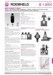
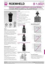
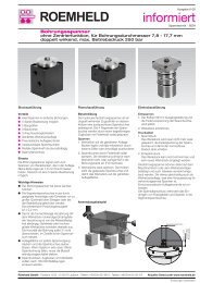
Fixture Clamp, Position Flexible<br />
max. clamping force 8 kN, jaw width 40 mm<br />
double acting, max. operating pressure 250 bar<br />
Application<br />
Position-flexible fixture clamps can additionally<br />
clamp and support a workpiece, which is<br />
already positioned and clamped in fixed stops,<br />
at unstable workpiece sections.<br />
Due to their compact design they can be<br />
arranged in a very limited space.<br />
Fixture clamps are especially suitable for<br />
series manufacturing in automated mode.<br />
The double-acting cylinder function combined<br />
with central lubrication and good swarf<br />
protection guarantees a high process safety.<br />
Description<br />
The fixture clamp with position-flexible<br />
clamping function consists of a very slim basic<br />
body with 2 integrated hydraulic cylinders.<br />
The piston forces are transmitted by two<br />
channels to the two clamping slides that can<br />
be moved independently from each other.<br />
During clamping both clamping slides contact<br />
the workpiece nearly without force<br />
(see page 3).<br />
Only after that the clamping pressure and<br />
thereby the clamping force increases. Due to<br />
wedging of the clamping slides these are protected<br />
against displacement. Thereby the<br />
workpiece is floatingly held without deformation.<br />
All threads and ports are at the bottom to<br />
allow a space-saving arrangement of several<br />
clamping points in a very limited space.<br />
If fixing from below is not possible an adaptor<br />
plate for manifold mounting or tube connection<br />
is available.<br />
As accessory also blanks of clamping jaws are<br />
available for adaptation to the workpiece<br />
contour.<br />
Advantages<br />
● Very compact design<br />
● High stiffness<br />
● High clamping force with low<br />
contact forces<br />
● Position flexible within the clamping range<br />
● Double-acting function<br />
● Fixtures without pipes possible<br />
● Exchangeable jaws<br />
● Good swarf protection<br />
● Port for central lubrication<br />
● Mounting position: any<br />
Fixing from above<br />
with accessory adaptor plate<br />
Drilled channels<br />
Pipe thread<br />
Accessories<br />
Clamping jaws and adaptor plate are not<br />
included in the delivery of the fixture clamp<br />
and have to be ordered separately as accessory.<br />
Function<br />
Issue 9-08 E<br />
I <strong>4.130</strong><br />
Clamping jaw<br />
Fixing from below<br />
Drilled channels<br />
Connecting insert<br />
Clamping jaw<br />
Application example<br />
Clamping fixture for a pedal of a freight vehicle.<br />
Römheld <strong>GmbH</strong> · Postfach 1253 · 35317 Laubach, Germany · Tel.: +49 (0) 64 05 / 89-0 · Fax: +49 (0) 64 05 / 89-211 Actual issue see www.roemheld.com<br />
Stroke<br />
Clamping principle Position-flexible<br />
fixture clamp<br />
Fixture clamp with fixed jaw<br />
Stroke<br />
Subject to change without prior notice
Part-no. 4413-080<br />
Technical characteristics<br />
Clamping force at 250 bar [kN] 8<br />
Retention force at 250 bar [kN] 10<br />
Min. operating pressure<br />
Min. unclamping pressure<br />
[bar] 25<br />
0.5 x clamping<br />
pressure<br />
Clamping stroke [mm] 2 x 8<br />
Jaw width [mm] 40<br />
Max. flow rate* [cm3/s] 17<br />
Stroke volume Clamping [cm3] 8,4<br />
Unclamping [cm3] 7<br />
Weight [kg] approx. 2.5<br />
* See page 3 “Position-flexible clamping”<br />
2<br />
I <strong>4.130</strong> / 9-08 E<br />
Accessory: Adaptor plate<br />
View from below<br />
A = Clamping<br />
B = Unclamping<br />
S = Central lubrication<br />
11<br />
20 f7<br />
40<br />
21,5<br />
3,5<br />
0<br />
13,5<br />
Important notes!<br />
The fixture clamp is only suitable for exterior<br />
clamping.<br />
Lubricate the clamping slide via the central<br />
lubrication at the latest after 500 clamping<br />
cycles. (Recommended: slide way oil ISO 69)<br />
Never use the complete clamping stroke to<br />
guarantee safe clamping of the workpiece.<br />
Max. operating temperature 80 °C.<br />
Operating conditions and other data see data<br />
sheet A 0.100.<br />
0<br />
21,5<br />
3,5<br />
0<br />
3,5<br />
14,5<br />
14<br />
12 ±0,01<br />
0<br />
12 ±0,01<br />
14<br />
14 ±0,01<br />
0,03<br />
Adaptor plate (accessory)<br />
Weight [kg] approx. 1.9<br />
Part-no. 0441-305<br />
8<br />
11<br />
A<br />
0<br />
70,5<br />
59 ±0,01<br />
45,5<br />
39 ±0,01<br />
A<br />
0<br />
7<br />
28,5<br />
0<br />
28,5<br />
A<br />
S<br />
B<br />
23,5<br />
Ø8 H7 (2x)<br />
54<br />
67,5<br />
77,5<br />
87,5<br />
0<br />
101 ±0,01<br />
67,5<br />
143<br />
87,5<br />
155<br />
170<br />
23,5<br />
101<br />
39 ±0,01<br />
45,5<br />
S B A S B A<br />
A<br />
Stroke<br />
G1/8 (3x) G1/8 (3x)<br />
B<br />
S<br />
S<br />
A<br />
B<br />
B<br />
112,5<br />
B<br />
S<br />
S<br />
59 ±0,01<br />
Technical data / Accessories<br />
Dimensions<br />
Socket head cap screw M6 x 20<br />
Part-no. 3300-225<br />
(included in the delivery)<br />
O-ring 8 x 1.5<br />
Part-no. 3000-275 (included in the delivery)<br />
Stroke<br />
70,5<br />
A<br />
25 11<br />
148<br />
A<br />
6<br />
14 ±0,01<br />
12 ±0,01<br />
0<br />
12 ±0,01<br />
14,5<br />
Ø10 H7x7 deep (4x)<br />
55<br />
12<br />
M6 x 8 deep (8x)<br />
5<br />
58 ±0,03<br />
22<br />
70<br />
Clamping force [kN]<br />
Ra = 0,8<br />
Ra = 0,8<br />
M6 x 8 deep (8x)<br />
Clamping force diagram<br />
(Height of the clamping jaw 15 mm)<br />
for socket head cap screw M6<br />
DIN EN ISO 4762<br />
8<br />
6<br />
4<br />
2<br />
0<br />
0 50 100 150 200 250<br />
Operating pressure [bar]<br />
Clamping and unclamping<br />
each Ø10 H7 x 7 deep for<br />
connecting insert 9210-132<br />
(included in the delivery),<br />
see also page F 9.300<br />
Central lubrication<br />
2 x with O-ring 3000-876 (3.68 x 1.78 mm)<br />
(included in the delivery)<br />
Accessory: Adaptor plate<br />
Side views<br />
Accessory: Adaptor plate<br />
View from above<br />
Subject to change without prior notice
Self-made clamping jaws<br />
Clamping jaws are manufactured according to<br />
the contour of the workpiece to be clamped.<br />
The max. height of the clamping jaw X at<br />
250 bar operating pressure is indicated in the<br />
opposite chart.<br />
If the operating pressure is lower, the clamping<br />
jaws can be designed higher as per the opposite<br />
diagram.<br />
Clamping jaw blank 40 mm<br />
Part-no. 3548-070<br />
0,5x45°<br />
40<br />
6<br />
12±0,1<br />
Support<br />
Ø6,6<br />
I <strong>4.130</strong> / 9-08 E<br />
11±0,1<br />
Ø11<br />
25±0,05<br />
15<br />
1,95-0,05<br />
Support face<br />
Fixing screws:<br />
2x M6x16 12.9<br />
Part-no. 3301-107<br />
Workpiece side<br />
Position-flexible clamping<br />
1. Position of the workpiece within the<br />
clamping range<br />
Contact force A Contact force B<br />
Max. stroke 8<br />
a b<br />
Workpiece<br />
Limit dimensions: a max. = 7 mm<br />
b max. = 7 mm<br />
Max. height of the clamping jaws X<br />
at max. operating pressure of 250 bar<br />
Fixing screws<br />
for clamping jaws M6x16 - 12.9<br />
X [mm] with 2 screws 15<br />
X [mm] with 4 screws 36<br />
20,05+0,05<br />
Material: 16 MnCr5 smooth<br />
Max. stroke 8<br />
Recommendation:<br />
Place the position-flexible fixture clamp as<br />
symmetrically as possible to the workpiece, so<br />
that the clamping jaws realise approximately<br />
the same stroke and also the smallest possible<br />
stroke.<br />
Important note<br />
The clamping jaws must always be supported<br />
by the provided support, since the fixing<br />
screws are not in the position to compensate<br />
the generated clamping forces.<br />
2. Possible contact forces during<br />
clamping<br />
Due to the slightly different factors of friction<br />
and an internal bracing spring the two<br />
clamping jaws do not uniformly contact the<br />
workpiece. One clamping jaw always hurries<br />
on ahead. This can already lead in case of<br />
very unstable sections to a deformation.<br />
The possible contact force can be taken from<br />
the diagram.<br />
3. Max. flow rate<br />
With a max. flow rate of 17 cm3/s the<br />
clamping time is approx. 0.5 seconds.<br />
For unstable workpieces and / or heavy<br />
clamping jaws the flow rate in the supply line<br />
should be throttled so that the clamping jaws<br />
contact the workpiece as „smoothly“ as<br />
possible.<br />
Accessories<br />
Position-flexible clamping<br />
Max. height of the clamping jaw X<br />
as a function of the operating pressure<br />
Max. height of the clamping jaw X [mm]<br />
100<br />
90<br />
80<br />
70<br />
60<br />
50<br />
40<br />
4 screws<br />
30<br />
20<br />
10<br />
0<br />
2 screws<br />
0 50 100 150 200 250<br />
Fixing of the clamping jaws<br />
Support<br />
100<br />
80<br />
60<br />
40<br />
20<br />
0<br />
0<br />
Clamping jaws<br />
Operating pressure [bar]<br />
4 screws<br />
or<br />
2 screws<br />
Contact force as a function of the stroke<br />
difference (a-b) or (b-a)<br />
Contact force A or B [N]<br />
1 2 3 4 5 6 7<br />
Stroke difference (a-b) or (b-a) [mm]<br />
Diagram valid for horizontal mounting position.<br />
For vertical arrangement the weight of the<br />
clamping jaws has to be considered.<br />
3<br />
Subject to change without prior notice