Mike Jones article.qxd:Layout 1 - Astronomy Technology Today
Mike Jones article.qxd:Layout 1 - Astronomy Technology Today
Mike Jones article.qxd:Layout 1 - Astronomy Technology Today

You also want an ePaper? Increase the reach of your titles
YUMPU automatically turns print PDFs into web optimized ePapers that Google loves.
Don’t Miss A Single Issue!www.astronomytechnologytoday.com
• In-House Testing• In-House Service• 100% Satisfaction• Over 100 Years Combined ExperienceWe Stock More Than3,500 Different Scopes,Parts, and Accessories!Zeiss, Meade, Celestron, Takahashi, Stellarvue, Vixen, Lumicon,Denkmeier, Vernonscope, Lunt, GTO, Thousand Oaks, JMI, Pentax,Sky Instruments, Proxima, Skywatcher, Coronado and Many More!26437 Ridge Road • Damascus, Maryland 20872www.handsonoptics.com1-866-726-7371
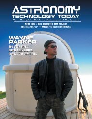
Baffle Optimizationfor CassegrainTelescopesBy <strong>Mike</strong> <strong>Jones</strong>Cassegrain telescopes require lightshielding, or baffles, to prevent unfocusedstarlight from passing around the secondarymirror, through the primary mirrorhole, and directly reaching focus. This unfocusedlight is in the form of plane waves,rather than spherical waves converging tothe desired focal point. The effect is to addbrightness to the image without structure,which uniformly reduces image contrastfor both visual and imaging usage.Stray light in any telescope can be easilyseen using the stacked eyepiece techniqueI described in the October 2007issue of <strong>Astronomy</strong> <strong>Technology</strong> <strong>Today</strong> 1 .Thetelescope is aimed into the daylight sky ata safe angle from the sun, and a mediumfocal length eyepiece with good eye reliefis inserted into the focuser. A second eyepiecewith a real focal plane, such as an orthoscopic,Kellner or Plossl design, is heldover the first eyepiece, and focused to givea sharp image of the exit pupil from theFigure 1. Stray light in an unbaffled Cassegrain (red light from star, green light random).first eyepiece. In a Cassegrain, if you cansee skylight around the secondary mirrorat the exit pupil, the baffling is not designedproperly.An example of an unbaffledCassegrain is shown in Figure 1. The randomlygenerated rays in red are from aninfinitely distant object and are thus allparallel, and come to focus as seen. Tenthousand randomly directed rays werethen spawned from a plane in front of thetelescope to simulate stray light and plottedin green. It is easy to see the paths unfocusedstray light (plotted in green) cantake to arrive at the focal plane withouthaving been focused by the telescope mirrors.Optimal design of Cassegrain bafflingis defined as the design that minimizescentral obscuration of the telescope’s primarymirror while fully shielding thespecified focal plane. This turns out to bea more complex problem than it first appears.The lengths of primary and secondarybaffle tubes drive their diameters,and their diameters drive the resultingcentral obscuration and light blockage ofthe telescope entrance pupil. The secondarymirror baffle opens up toward the primary,and will in general always be largerthan the secondary mirror itself. If the primarybaffle is too short, the secondarybaffle must be larger to block light, whichincreases obscuration. As the primary bafflegrows longer, the secondary baffle diametercan shrink, but then the primarybaffle begins to intrude into light from theinner portion of the primary mirror, again<strong>Astronomy</strong> TECHNOLOGY TODAY 51
BAFFLE OPTIMIZATION FOR CASSEGRAIN TELESCOPESFigure 2. Ray 1 is traced first, giving the secondary mirror and primary hole diameter.Figure 3. Ray 2 is traced next, starting at the upper rim of the secondary baffle.acting as a central obstruction. Either extremecreates a larger central obstruction;the design goal is to find the minimumblockage that still shields the full focalplane. As will be seen, and contrary tosome prior published work, this does notnecessarily mean that the secondary andprimary baffle obscurations have the samevalues at the optimum.Several papers have appeared over thedecades describing various graphical andcomputer methods for achieving orapproximating optimal baffle design.Andrew Young’s 1967 paper 2 was the firstto describe an iterative algorithm thataccounts for mirror curvature, and thefirst to discuss the option of inclusion ofbaffle design in optical design codes usingmacro languages. Rochelle Prescott’spaper 3 simplifies baffle optimization toa graphical method, but approximatesthe mirrors as flat surfaces. The paperby Hales 4 presents a lengthy but closedform,calculator-friendly algorithm foroptimal baffle design, with the onlyThe Largest Telescope & Binocular Dealerin the New York Metropolitan AreaFast DeliverySame Dayon ManyProductsCCTSCAMERA CONCEPTS & TELESCOPE SOLUTIONSwww.cameraconcepts.comAt CCTS, the owners, Jeff and Greta, take a hands-on approach tocustomer service. Call them direct at 631-335-1279YOU NAME IT…WE HAVE IT!• Televue 13mm and 8mm Ethos in Stock and Ready forFree Shipping• Full Line Meade Telescopes and Accessories Dealer• Full Line Coronado Dealer• Full Line Daystar Dealer• Celestron Premier Showcase Dealer• Full Line Orion Dealer - Buy Direct from Us at ReducedShipping Charges• Largest Library of <strong>Astronomy</strong> Books in the Northeast• Dew-not Heaters• Baader Solar Filters• Arcturus Exclusive Photo/Visual Accessories• Feathertouch Focusers in stock• Digital Camera Adapters• Denkmeier Binoviewer Cosmetic defect units available -great price• Desert Storm Covers are Back Starting at Only $25• Universal Astronomics Unimount Light DeluxeOnly $299.99• Celestron BIG Binos at a Small Price Tag• Fingerless Astro Gloves with Built in Thinsulate MittenOnly $18.00• CCTS Twist Pack Eyepiece Cases• And So Much More We’re OverflowingWe travel coast to coast to over 20 star parties and events a year - check out our website for the schedule.We’ll see you there! Or Visit us at 10 South Ocean Ave Patchogue, NY 11772 • 631-475-1118Arcturus OpticsA CCTS Exclusive!The only 5 element APOBarlows on the markettoday! As low as $129Ultra Wide eyepiece with awhopping 20mm of eye relief!As low as $89.95Super Wide eyepieces allwith 70 degree apparentfields! As low as $4952 <strong>Astronomy</strong> TECHNOLOGY TODAY
BAFFLE OPTIMIZATION FOR CASSEGRAIN TELESCOPESapproximations being that both mirrorsare spherical rather than aspheric. Thisapproximation has minimal impact on themechanical dimensions of the baffles.Hales’ method does not require iteration,but does require solution of a fourth orderquartic and selection of the proper root.The Young and Hales papers also bothbegin with the assumption that thesecondary and primary obscurations mustbe solved to be equal, which is not actuallythe case.Baffle OptimizationI developed the method shown in thisATT <strong>article</strong> independent of publishedwork, at first in Visual Basic and implementedin the CassDesign program, andthen in the ZEMAX 5 macro language.This method makes no approximations,and can handle higher-order aspheric mirrorsas well as conics. This approximationfree,3-ray baffle numerical optimizationmethod presented here is different fromprevious published methods in that it iterativelysolves for the baffle design thatprovides the best shielding, rather thantrying to force the secondary and primaryobscurations to be the same.Optimization of Cassegrain bafflingcan be accomplished by tracing three rays,and iterating the baffle design to achievesimultaneous intersections of the threerays in a common plane, described separatelyin Figures 2, 3, and 4, and plottedtogether in Figure 5.The basic telescope radii, spacing andconics are designed first, with a first guessat the secondary mirror diameter beingthe primary mirror diameter dividedby the secondary amplification. Thetelescope field of view (FOV) and imagedimensions are specified to accommodatethe desired range of viewing and imagingdevices. For square or rectangularimaging arrays, the maximum FOV isthe radial distance out to the corner of theformat.To start the iteration process, a beginningvalue for the secondary baffleFigure 4. Ray 3 is the cross-ray from the top of the secondary baffle to the bottom of the image.Figure 5. All three rays used for baffle optimization, and their intersection points.<strong>Astronomy</strong> TECHNOLOGY TODAY 53
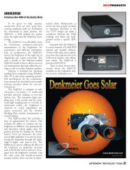
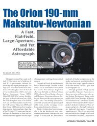
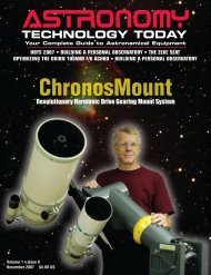
BAFFLE OPTIMIZATION FOR CASSEGRAIN TELESCOPESDon’t Buy DisappointmentThe Half Hitch Delivers Solid SatisfactionShake-free focusing and trackingfrom a mount weighing justfive and a quarter pounds• CNC machined and anodized• Backlash-free motion controls• No clutches or counterweights• Vise-like dovetail system included• Two-axis balancing keeps your scope on target without heavy friction• Disc brake for changing eyepieces• Rigid cross-braced design• Precision encoder installation and folding DSC bracket• Excellent tripod clearance means no column extension needed• Preloaded Timken bearings mean no slop• Centerline loading for superior stability andperformance from your tripodDon’t skimp on one of the most critical components in yourtelescope. Get the most from your expensive premium optics.www.halfhitchtelescope.comIntroducing the TrueRCastrograph series fromDeep Sky InstrumentsRC10 (uncorrected): $4,995 (Introductory price)RC10C (corrected): $ 5,995 (Introductory price)We offer two versions in theTrueRC series depending on yourrequirements. The RC10 providesRitchey-Chrétien performance freefrom coma, spherical aberration andfirst-order astigmatism. The RC10Cadds a corrector/field flattener to removethird-order astigmatism andflatten the field for excellent star imageson even today's largest CCD cameras. Both astrographs featureoptics by Star Instruments, maker of RC optics for over 30 years.535 Pine Road, Suite 204 • Newnan, Georgia 30263www.deepskyinstruments.comlength (call this the variable “TBS”) is selected.A good starting value is about onethirdof the semi-diameter of thesecondary mirror determined by the approximationgiven above. A dummy surfaceat the rear of the secondary baffle isincluded in the raytracing.Ray 1 (shown in blue in Figure 2) istraced first. Ray 1 is the ray from the lowestsemi-field angle, traced in an ascendingdirection to the upper rim of the primarymirror P 1-1 , then to the rear plane of thesecondary baffle P 1-2 , and then to thesecondary mirror P 1-3 . It then interceptsthe plane at the front of the primary baffleat P 1-4 , returns to and through theprimary surface at P 1-5 , and terminatesat the uppermost point in the image planeP 1-6 . This ray precisely defines the diameterof the Cassegrain secondary requiredfor 100 percent field illumination, and theminimum diameter of the hole throughthe Cassegrain primary mirror. The programmodifies the initial Cassegrain designmodel with the new values for thesecondary and primary hole diameters.Ray 1 segment (P 1-3 – P 1-6 ) is used forbaffle optimization.Ray 2 (shown in red in Figure 3) istraced next. Ray 2 is sloped downwardfrom the upper point in semi-field angle,but instead of being traced from the sky, itbegins at the upper point on the rear ofthe secondary baffle determined byRay 1 (P 1-2 in Figure 2 and P 2-1 in Figure3, which have identical coordinates).It descends to the primary mirror intersectionP 2-2 , then reflects to the frontplane of the primary baffle tube P 2-3 ,andthen to secondary mirror P 2-4 . Ray 2then proceeds to the lowest point in theimage at P 2-5 . Ray 2 segment (P 2-2 –P 2-4 ) determines the taper of the primarybaffle as well as being used for baffleoptimization.Ray 3 (shown in green in Figure 4) isthe cross-ray from the upper point P 3-1on the upper rear of the secondary baffletube to the lower point P 3-3 in the image.Ray 3 is not actually raytraced; its direc-54 <strong>Astronomy</strong> TECHNOLOGY TODAY
BAFFLE OPTIMIZATION FOR CASSEGRAIN TELESCOPESFigure 6. Formulas for intersection of any two 2-D linesTable 1. Fast Cassegrain design used to demonstrate baffle optimizer algorithmtion cosines are simply calculated from thecoordinates of its endpoints P 3-1 andP 3-3 .Figure 5 shows all three rays superimposed.The circles are color-coded toshow which rays are common to any givensurface or ray intersection.The three intersections of Rays 1-2,Rays 1-3 and Rays 2-3 are now calculated.The formulas for intersection of any tworays in 2-D is given in Figure 6. Line endpointcoordinates are (x ij , y ij ), K i is thedirection cosine component for the i th rayalong the x-axis, L is the direction cosinecomponent for the i th ray along the y-axis, and D 1 is the distance from(x 11 ,y 11 ) to intersection point (x i ,y i ).Using this formulation, the followingray segments are intersected: Ray 1 segment(P 1-3 – P 1-6 ) and Ray 2 segment(P 2-2 – P 2-4 ) give plane P 12 ;Ray 1 segment(P 1-3 – P 1-6 ) and Ray 3 give planeP 13, and ;Ray 2 segment (P 2-2 – P 2-4 )and Ray 3 give plane P 23 .The optimal baffle design occurswhen P 12 , P 13 and P 23 converge to thesame location along the optical axis, makingthem coplanar. Their convergence locationis the front of the optimizedprimary baffle tube.A very fast Cassegrain was designedto test the algorithm, with the prescriptionshown in Table 1. The primary is anf/1.5 paraboloid, and the overall system isonly f/3.6. A large field diameter of 3.0inches was used to increase the separationbetween the unoptimized planes and improveplotting visibility.A GOTO statement was added tojump over the optimization macro codeand plot the starting baffle configuration.Figure 7 shows the locations of the P 12 ,P 13 and P 23 planes for the starting nonoptimalguess of TBS, and that they areseparated and not coplanar.A simple Newton-Raphson iterativeprojective technique is used to rapidlySubscribe Now!!!Print and OnlineIssues NowAvailable!ASTRONOMYTECHNOLOGY TODAYwww.astronomytechnologytoday.com<strong>Astronomy</strong> TECHNOLOGY TODAY 55
BAFFLE OPTIMIZATION FOR CASSEGRAIN TELESCOPESFigure 7. Non-optimal baffling showing separation between planes P 12 , P 13 and P 23 .bring planes P 12 , P 13 and P 23 tocoplanarity. Figure 8 shows theimplementation.The horizontal axis is the value of thelength of the secondary baffle TBS. Thevertical axis is the difference between thedistance d 1 =d 12-13 between planes P 12–P 13 and the distance d 2 =d 13-23 betweenP 13 -P 23 along the optical axis.The initial value for TBS gives the differencebetween d 1 and d 2 . A small differentialvalue, say 0.001", is added to TBSand the subroutine to calculate the d 1 -d 2difference is called again. This gives a newdifference value shown as d 2 . The linearprojection of this line to the horizontalaxis at d 1 -d 2 =0 gives the estimated valueof TBS required to bring the two planesto coplanarity. This value is added to theinitial value of TBS, and the differencevalue is re-calculated.If both mirror surfaces were approximatedas planes as in Prescott’s paper, thistechnique would give the exact length ofthe secondary baffle tube in one linear solutioncycle. But because both mirror surfacesare aspherically curved, the linearprojection step is an approximation to theoptimal value, and the process must be repeateda few times until convergence isreached. Four to five cycles has shown tobe enough in all cases tested, even for veryfast, strongly aspheric Cassegrain primar-56 <strong>Astronomy</strong> TECHNOLOGY TODAY
BAFFLE OPTIMIZATION FOR CASSEGRAIN TELESCOPESFigure 8. Projective Newton-Raphson iteration technique used for baffle optimization.ies and systems. A numerical example ofthis convergence process is given inTable 2. “Delta TBS” is the value addedto the length of the secondary bafflelength at each iteration cycle. Notice howrapidly Delta TBS reduces, and how thelength of the primary baffle tube converges,at each iteration cycle.The technique is seen to convergerapidly, in what is termed quadratic convergence,where the residual error isroughly the square of the previous error.In quadratic convergence, if the initialerror is, say, 0.1 inches, the error valueafter Cycle 1 is 0.1 2 =0.01 in., then is0.01 2 =0.0001 in. after Cycle 2,0.0001 2 =0.00000001 in. after Cycle 3,etc. The fourth or fifth iteration cycle onall cases tested gives convergence of theplanes to about the diameter of a proton,which for die-hard ATM’s is just barelyclose enough :o).When the baffles for the very fast systemin Figure 7 have been optimized withthis algorithm, the optimally baffled systemprescription is shown in Table 3, andplotted in Figure 9.The convergence of all three planes inFigure 9 gives the secondary baffle lengthTBS and resulting primary baffle tubelength that gives the optimal system bafflingwith 100% stray light shielding forthe specified image format and FOV withminimal pupil obscuration. Notice in Figure9 that for the very strongly curvedmirrors and large image formats used inthis example, optimal baffling does notnecessarily mean that the primary and secondarybaffles result in the same obscuration;the primary baffle is seen to beslightly smaller than the secondary baffle<strong>Astronomy</strong> observatories for the amateur and professional astronomer,Designed and Manufactured in Australia and exported around the globe since 1986We ship to anywhere in the world2.3m Home Model 3.5m School Model 6.7 University ModelFeatures: Motorised or Manual rotation and shutter operation. Dome only options all models.Computerised (ASCOM compatible). Stainless Steel fittings. Completely waterproof.www.siriusobservatories.com New 5m College Model now available info@siriusobservatories.com<strong>Astronomy</strong> TECHNOLOGY TODAY 57
BAFFLE OPTIMIZATION FOR CASSEGRAIN TELESCOPESTable 3. Optimized baffle design prescription for fastCassegrain example.Table 2. Example of the numerical convergence of the baffle optimizationalgorithm.shadow. This difference in obscurationsdiminishes for slower primaries andsmaller image formats.MakingBaffle TubesBaffling is usuallybuilt fromthin, stiff sheetmetal, but can alsobe made from thincarbon fiber laminatelayups. Theinterior and exteriorsurface shouldideally be dead flatblack with nosheen or luster visibleeven down tonear-graze angle.The surfaces canbe sandblasted orglass bead peenedto roughen themetal surface, and a very flat black paintapplied, such as Krylon Ultra-Flat Black,Aeroglaze Z306 6 , or a high-temperatureblack paint for barbeque grills, exhaustmanifolds, etc. The paint is lightly appliedin thin multiple coats to avoid shiny, reflectivepooling of the paint binder.Baffles can be cylindrical and thuseasy to make. However, at near-graze angleseven the blackest, most diffuse surfacescan become specular (mirror-like),and graze-angle stray light can reflect specularlyfrom interior and exterior surfaces,partially defeating the benefit of the baffling.Conical baffles can be used ratherthan cylindrical baffles, with the taper anglesdesigned to minimize visibility as seenfrom both mirrors and at focus. Puristsmay even add additional baffle stops insidethe tapered primary mirror baffle,similar to baffling a refractor, to furthertrap stray light.ConclusionI have posted CassDesign2 (CD2),which implements the algorithm de-Mark Rieck, Ownerwww.tetontelescope.com(208)403-4339COME SEE THE VIEWFROM THE TOP!2nd AnnualMakNewt Madness Sale!FREE SHIPPING plus FREE DEWSHIELD• If you've always wanted apo refractorperformance, but couldn't afford the price,Intes Micro MakNewts are the answer for you• Custom machining or tailor the accessoriesyou want with our Teton MakNewt options• Tailoring exactly the right scope for your needs is our specialty• Unparalleled service both before and after the sale58 <strong>Astronomy</strong> TECHNOLOGY TODAY
BAFFLE OPTIMIZATION FOR CASSEGRAIN TELESCOPESscribed here, in the Files section of theYahoo group “<strong>Astronomy</strong> <strong>Technology</strong><strong>Today</strong>.” Regarding any licensing issues, Isimply certify that CassDesign2 is beingmade available to the public totally free ofcharge, with no fees or sharewaredonation requests, but with no liability tome. Download it, play with it, use it for areal system you build, and please reportany errors you encounter on theYahoo ATT group site. I have a real dayjob in optics; CD2 is strictly for fun.Enjoy!Bibliography:1. <strong>Jones</strong>, M.I., “Stray Light Revealed”,<strong>Astronomy</strong> <strong>Technology</strong> <strong>Today</strong>, Oct.2007, Issue 5, pp. 26-27.2. Young, A.T., “Design of CassegrainLight Shields”, Applied Optics, Vol. 6,No. 6, June, 1967, pp. 1063-1067.3. Prescott, R., “Cassegrainian Baffle Design”,Applied Optics, Vol. 7, No. 3,March 1968, pp. 479-481.Figure 9. Optimal baffling for the system in Figure 7.4. Hales, W.L., “Optimum CassegrainBaffle Systems”, Applied Optics, Vol. 31,No. 25, September, 1992, pp. 5341-5344.5. ZEMAX® is an optical design softwareproduct of the ZEMAX DevelopmentCorporation, 3001 112th AvenueNE, Suite 202, Bellevue, WA 98004-8017 USA, www.zemax.com.6. Aeroglaze Z306 black absorptivepolyurethane is available from the LordCorporation, 2000 West GrandviewBlvd., P.O. Box 10038, Erie, PA 16514-0038, 814/868-3611 ext. 3277,www.lordfulfillment.com.<strong>Astronomy</strong> TECHNOLOGY TODAY 59