You also want an ePaper? Increase the reach of your titles
YUMPU automatically turns print PDFs into web optimized ePapers that Google loves.
<strong>Agilent</strong> <strong>ADNS</strong>-<strong>2051</strong><strong>Optical</strong> <strong>Mouse</strong> <strong>Sensor</strong>Data SheetDescriptionThe <strong>ADNS</strong>-<strong>2051</strong> is a low costoptical sensor used to implementa non-mechanical tracking enginefor computer mice.It is based on optical navigationtechnology, which measureschanges in position by opticallyacquiring sequential surfaceimages (frames) and mathematicallydetermining the directionand magnitude of movement.The sensor is in a 16 pin opticalpackage that is designed to beused with the HDNS-2100 Lensand HDNS-2200 Clip. Theseparts provide a complete andcompact mouse sensor. Thereare no moving parts, and precisionoptical alignment is notrequired, facilitating high volumeassembly.The output format is two channelquadrature (X and Y direction)which emulates encoderphototransistors. The current Xand Y information are also availablein registers accessed via aserial port.Photo HereDefault resolution is specified as400 counts per inch, with ratesof motion up to 14 inches persecond.Resolution can also beprogrammed to 800 cpi.The part is programmed via a twowire serial port, via registers.Theory of OperationThe <strong>ADNS</strong>-<strong>2051</strong> is based on<strong>Optical</strong> Navigation Technology.It contains an Image AcquisitionSystem (IAS), a Digital SignalProcessor (DSP), a two-channelquadrature output, and a twowire serial port.The IAS acquires microscopicsurface images via the lens andillumination system provided bythe HDNS-2100, 2200, andHLMP-ED80. These images areprocessed by the DSP to determinethe direction and distanceof motion. The DSP generatesthe ∆x and ∆y relative displacementvalues that are convertedinto two channel quadraturesignals.Features• <strong>Optical</strong> navigation technology• No mechanical moving parts• High reliability• Complete 2-D motion sensor• High speed motion detector• No precision optical alignment• Wave solderable• Single 5.0 volt power supply• Shutdown pin for USB suspendmode operation• Power conservation mode duringtimes of no movement• On chip LED drive with regulatedcurrent• Serial port registers— Programming— Data transferApplications• Mice for desktop PCs,workstations, and portable PCs• Trackballs• Integrated input devices
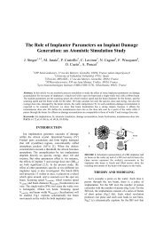
PinoutPin Pin Description1 SCLK Serial port clock (input)2 XA XA quadrature output3 XB XB quadrature output4 YB YB quadrature output5 YA YA quadrature output6 XY_LED LED control7 REFA Internal reference8 REFB Internal referenceSCLK 1XA 2XB 3YB 4YA 5XY_LED 6A<strong>2051</strong>YYWW161514131211SDIOPDR_BINV DDGNDOSC_OUT9 OSC_IN Oscillator input10 GND System ground11 OSC_OUT Oscillator output12 GND System groundREFA 7REFB 8109GNDOSC_IN13 V DD 5.0 volt power supply14 R_BIN LED current bin resistor15 PD Power down pin, active highFigure 1. Top view.16 SDIO Serial data (input and output)A<strong>2051</strong>YYWWPIN 122.30(0.878)0.99(0.039)3.18(0.125)9.10(0.358)5.15(0.203)0.50LEAD WIDTH(0.020)1.42(0.056)0.25(0.010)LEAD OFFSET1.27(0.050)2.54LEAD PITCH(0.100)KAPTON TAPE12.34(0.486)5° TYP.6.17(0.243)13.38(0.527)6.02(0.237)∅ 5.60(0.220)4.55(0.179)∅ 0.80(0.032)NOTES:1. DIMENSIONS IN MILLIMETERS (INCHES).2. DIMENSIONAL TOLERANCE: ± 0.1 mm.3. COPLANARITY OF LEADS: 0.1 mm.4. LEAD PITCH TOLERANCE: ± 0.15 mm.5. CUMULATIVE PITCH TOLERANCE: ± 0.15 mm.6. ANGULAR TOLERANCE: ± 3.0 DEGREES.7. MAXIMUM FLASH + 0.2 mm.8. CHAMFER (25 DEGREES x 2) ON THE TAPER SIDE OF THE LEAD.Figure 2. Package outline drawing.2
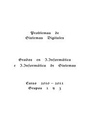
2D Assembly Drawing of <strong>ADNS</strong>-<strong>2051</strong>Shown with HDNS-2100,HDNS-2200, and HLMP-ED80.<strong>Agilent</strong> Technologies provides anIGES file drawing describing thebase plate molding features forlens and PCB alignment.1.27(0.050)2.32(0.091)40.53(1.596)39.39(1.551)30.32(1.194)The components interlock asthey are mounted onto definedfeatures on the base plate.The <strong>ADNS</strong>-<strong>2051</strong> sensor isdesigned for mounting on athrough hole PCB, looking down.There is an aperture stop andfeatures on the package thatalign to the lens.The HDNS-2100 lens providesoptics for the imaging of thesurface as well as illumination ofthe surface at the optimum angle.Features on the lens align it tothe sensor, base plate, and clipwith the LED. The lens also has alarge round flange to provide along creepage path for any ESDevents that occur at the openingof the base plate.The HDNS-2200 clip holds theLED in relation to the lens. TheLED must be inserted into theclip and the LED’s leads formedprior to loading on the PCB. Theclip interlocks the sensor to thelens, and through the lens to thealignment features on the baseplate.12.60(0.498)11.38(0.448)1.28(0.050)Figure 3. Recommended PCB mechanical cutouts and spacing.+y+xCLEAR ZONE44.29(1.744)PLASTIC SPRING7.50(0.295)BASE PLATEESD LENS RINGCLIP5.10(0.201)1.22(0.048)19.10(0.752)13.88(0.546)The HLMP-ED80 LED is recommendedfor illumination. If usedwith the bin table, sufficient illuminationcan be guaranteed.14.58(0.574)10.58(0.417)13.82(0.544)7.45(0.293)SENSORBASE PLATEALIGNMENT POSTPCBDIMENSIONS IN MILLIMETERS (INCHES).Figure 4. 2D assembly drawing of <strong>ADNS</strong>-<strong>2051</strong>.3
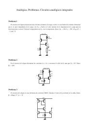
SERIAL PORTSCLKSDIOSERIAL PORTOSCILLATOROSC_INOSC_OUTRESONATORQUADRATUREOUTPUTSLEDXAXBYAYBR_BINXY_LEDQUADRATUREOUTPUTLEDDRIVEPOWER ONRESETIMAGEPROCESSORVOLTAGE REGULATORAND POWER CONTROLREFAREFBPDV DDGNDGNDVOLTAGEREFERENCE5 VOLTPOWERFigure 6. Block diagram.Design Considerations for ImprovingESD PerformanceThe flange on the lens has beendesigned to increase the creepageand clearance distance for electrostaticdischarge. The tablebelow shows typical values assumingbase plate constructionper the <strong>Agilent</strong> supplied IGES fileand HDNS-2100 lens flange.Typical DistanceCreepage 16.0Clearance 2.1MillimetersFor improved ESD performance,the lens flange can be sealed (i.e.glued) to the base plate.Note thatthe lens material is polycarbonateand therefore, cyanoacrylatebasedadhesives or otheradhesives that may damage thelens should NOT be used.The trimmed lens, HDNS-2100-001, is not recommended for thecorded application due to theESD spec requirement.SENSORCLIPPCBLEDLENS/LIGHT PIPEBASE PLATESURFACEFigure 7. PCB assembly.5
Recommended Typical Application using SDIO PinsXY_LED2.2 µF 0.1 µF0.1 µF13VHDNS-2100DD12INTERNALLENSHLMP-ED8012IMAGEV DDGND SENSORV7 DD VPPSURFACE10GND615.0 MV SS 15.0 ND+13 D+ CYPRESSCY7C63723A-PC1815D-12D-P0.4PD9OSC_INCERAMIC RESONATOR1.3 kΩ<strong>ADNS</strong>16<strong>2051</strong>18 MHz8GNDV REGP0.5 17SDIOAVX KBR-18-00-MSA11OSC_OUTMURATA CSALS18M0X55-B0SHLDGND QA5P1.0P0.6 167141P1.1P0.7 15REFAV SCLKDD V DD QB0.1 µF 2.2 µFP0.3 4 8REFBL1 2XA XB YB YA(kΩ) BINP0.0 P0.1 R2 3 4 5R115.0 KRΩP0.2 314R_BINMR1 VALUE LEDZ LEDBUTTONS15.0 L15.015.0 ~ 18.0PQXTALOUT XTALIN15.0 ~ 22.015.0 ~ 27.015.0 ~ 33.015.0 ~ 37.0RSTUFigure 8. Application using SDIO pins.Notes on Bypass Capacitors:• Caps for pins 7, 8 and 12, 13MUST have trace lengths LESSthan 5 mm.• The 0.1 µF caps must beceramic.• Caps should have less than5 nH of self inductance• Caps should have less than0.2 Ω ESRSurface mount parts arerecommended.Regulatory Requirements• Passes FCC B and worldwideanalogous emission limitswhen assembled into a mousewith unshielded cable and following<strong>Agilent</strong> recommendations.• Passes EN61000-4-4/IEC801-4EFT tests when assembled intoa mouse with unshielded cableand following <strong>Agilent</strong> recommendations.• UL flammability level UL94 V-0.• Provides sufficient ESD creepage/clearancedistance to avoiddischarge up to 15 kV whenassembled into a mouse accordingto usage instructionsabove.• For eye safety consideration,please refer to the technicalreport available on the web site,http://www.semiconductor.agilent.com• The 15.0 kΩ resistor is determinedby the absolute maximumrating of 50 mA for theHLMP-ED80. The other resistorvalues for brighter bins willguarantee good signals withreduced power.6
Alternative Application using Quadrature Output Pins2.7 Ω2.2 µF 0.1 µF131.5 MΩV12DD INTERNAL12IMAGEV DDGND SENSOR9 CEXT10GNDCYPRESSXY_LED0.33 µFCY7C63001A-PC2V DD P0.12XAOSC_INBUTTONSV SS V PP<strong>ADNS</strong>143D–D+P0.0 1 XB <strong>2051</strong>OSC_OUT4D+133D–P0.2YB105XTALINP0.3 4 REFAGNDYA1.3 MΩ15SHLD6 MHzP1.1 16 PDREFB111XTALOUTP1.3 15SCLKR_BIN6 516P1.0SDIOM P1.219 P0.617R P0.520 18P0.7L P0.47 8PANASONICEVQ SERIES ENCODERZ-WHEEL69117814HDNS-2100LENSSURFACER118 MHz0.1 µFHLMP-ED80CERAMIC RESONATORAVX KBR-18-00-MSAMURATA CSALS18M0X55-B02.2 µFR1 VALUE(kΩ)15.015.015.015.015.015.0 ~ 18.015.0 ~ 22.015.0 ~ 27.015.0 ~ 33.015.0 ~ 37.0LEDBINKLMNPQRSTUFigure 9. Application using quadrature output pins.Notes on Bypass Capacitors:• Caps for pins 7, 8 and 12, 13 MUST have trace lengths LESS than5 mm.• The 0.1 µF caps must be ceramic.• Caps should have less than 5 nH of self inductance• Caps should have less than 0.2 Ω ESRSurface mount parts are recommended.Absolute Maximum RatingsParameter Symbol Min. Max. Units NotesStorage Temperature T S –40 85 ˚COperating Temperature T A –15 55 ˚CLead Solder Temperature 260 ˚C For 10 seconds, 1.6 mm below seatingplane.Supply Voltage V DD –0.5 5.5 VESD 2 kV All pins, human body model MIL 883Method 3015Input Voltage V IN –0.5 V DD + 0.5 V PD, SDIO, SCLK, XA, XB, YA, YB, XY_LED,R_BINInput Voltage V IN –0.5 3.6 V OSC_IN, OSC_OUT, REF_A7
Recommended Operating ConditionsParameter Symbol Min. Typ. Max. Units NotesOperating Temperature T A 0 40 ˚CPower Supply Voltage V DD 4.25 5.0 5.5 volts Register values retained forvoltage transients below4.25 V but greater than 4 V.Power Supply Rise Time V RT 100 msSupply Noise V N 100 mV Peak to peak within0-100 MHz.Clock Frequency f CLK 17.l4 18.0 18.7 MHz Set by ceramic resonator.Serial Port Clock Frequency SCLK f CLK /4 MHzResonator Impendance X RES 55 ΩDistance from Lens Reference Z 2.3 2.4 2.5 mm Results in ±0.2 mm DOF.Plane to Surface (See Figure 10.)Speed S 0 14 in/sec @ frame rate = 1500/second.Acceleration A 0.15 g @ frame rate = 1500/second.Light Level onto IC IRR INC 80 25,000 mW/m 2 λ = 639 nm100 30,000 λ = 875 nmSDIO Read Hold Time t HOLD 100 µs Hold time for valid data.(Refer to Figure 28.)SDIO Serial Write-Write Time t SWW 100 µs Time between two writecommands. (Refer to Figure 31.)SDIO Serial Write-Read Time t SWR 100 µs Time between write and readoperation. (Refer to Figure 32.)SDIO Serial Read-Write Time t SRW 120 ns Time between read and writeoperation. (Refer to Figure 33.)SDIO Serial Read-Read Time t SRR 120 ns Time between two readcommands. (Refer to Figure 33.)Data Delay after PD t COMPUTE 3 ms After t COMPUTE , all registerscontain data from first imageafter PD . Note that an additional75 frames for AGCstabilization may be required ifmouse movement occurredwhile PD was high. (Refer toFigure 12.)SDIO Write Setup Time t SETUP 60 ns Data valid time before the risingof SCLK. (Refer to Figure 26.)PD Pulse Width t PDW 700 µs Pulse width to initiate the power(to power down the chip)down cycle @ 1500 fps. (Referto Figure 14.)PD Pulse Width t PD 100 µs Pulse width to reset the serial(to reset the serial port)port @ 1500 fps (but may alsoinitiate a power down cycle.(Refer to Figure 14.)Frame Rate FR 1500 frames/s See Frame_Period registersection.Bin Resistor R1 15 K 15 K 33 K Ω Refer to Figure 8.←←8
<strong>ADNS</strong>-<strong>2051</strong>HDNS-2100ZOBJECT SURFACEFigure 10. Distance from lens reference plane to surface.AC Electrical SpecificationsElectrical Characteristics over recommended operating conditions. Typical values at 25˚C, V DD = 5.0 V, 1500 fps, 18 MHz.Parameter Symbol Min. Typ. Max. Units NotesPower Down t PD 700 µs From PDTime uncertainty due to firmwaredelay. (Refer to Figure 12.)Power Up from PD t PUPD 50 ms From PD to valid quad signals555 µsec + 75 frames. (Refer toFigure 12.)Power Up from V DD t PU 30 ms From V DD to valid quadsignals555 µsec + 40 frames←←Rise and Fall Times: SDIO t r 30 ns C L = 30 pF (the rise time isbetween 10% and 90%)t f 16 ns C L = 30 pF (the fall time isbetween 10% and 90%)XA, XB, YA, YB t r 50 ns C L = 30 pF (the rise time isbetween 10% and 90%)t f 20 ns C L = 30 pF (the fall time isbetween 10% and 90%)ILED t r 40 ns With HLMP-ED80 LED (the risetime is between 10% and 90%)t f 200 ns With HLMP-ED80 LED (the falltime is between 10% and 90%)Serial Port Transaction Timer t SPTT 0.7 0.9 1.0 s Serial port will reset if currenttransaction is not completewithin t SPTT . (Refer to Figure 36.)Serial Port Transaction Timer t SPTT 1.0 s Serial port reset completedand ready for new transaction.(Refer to Figure 36.)Transient Supply Current I DDT 20 37 mA Max. supply current during aV DD ramp from 0 to 5.0 V with> 500 µs rise time.←←←9
DC Electrical SpecificationsElectrical Characteristics over recommended operating conditions. Typical values at 25˚C, V DD = 5.0 V, 18 MHz.Parameter Symbol Min. Typ. Max. Units NotesDC Supply Current I DD AVG 15 25 mA No load on XA, XB, YA, YB,(mouse moving)SCLK, SDIO excluding LEDcurrentPeak Supply Current I DD PEAK 20 mA No load on XA, XB, YA, YB,(mouse moving)SCLK, SDIO excluding LEDcurrentDC Supply Current I DD 12 25 mA No load on XA, XB, YA, YB,(mouse not moving)SCLK, SDIO excluding LEDcurrentDC Supply Current I DDPD 170 230 µA PD = high; SCLK, SDIO = GND(power down) or V DD ; V DD = 4.25 V to 5.25 V.SCLK, SDIO, PDInput Low Voltage V IL 0.8 VInput High Voltage V IH 0.5 * V DD VOutput Low Voltage V OL 0.7 V @ I OL = 2 mA (SDIO only)Output High Voltage V OH 0.6 * V DD V @ I OH = 2 mA (SDIO only)Output Low Voltage V OL 0.4 V @ I OL = 0.5 mA.(XA, XB, YA, YB)Output High Voltage V OH 0.6 * V DD V @ I OH = 0.5 mA .(XA, XB, YA, YB)Output Low Voltage V OL 1.1 V Refer to Figure 11.(LED)XY LED Current I LED Typ–15% 630/R1 Typ + 15% A Refer to Figure 11, see tablebelow.XY LED Current I LED 500 µA R1 < 200 Ω.(fault mode)REF_A (normal mode) V REFA 3.3 V 1.5 KΩ to 3.0 V or GND,PD = low.REF_A (power down mode) V REFA 3.3 V 1.5 KΩ to 3.0 V or GND,PD = high.NORMALIZED I LED – %10080604020R = 15 kR = 30 k00 0.5 1.0 1.5 2.0 2.5 3.0 3.5cannot read axis label...Typical LED Current TableR1 Value kΩ 15 18 22 27 33 37LED current (typical) mA 42 35 29 23 19 17Figure 11. Typical I-V characteristic of<strong>ADNS</strong>-<strong>2051</strong> XY_LED pin.10
PD Pin TimingPDI DDt PD75 FRAMES555 µst PµPDFigure 12. PD timing normal mode.t COMPUTE (SEE FIGURE 13)PDI LEDPDSCLKt PDWREGISTERREAD OPERATIONFigure 13. PD timing sleep mode.t COMPUTE~ 700 µs(POWER DOWN)Figure 14. PD minimum pulse width.PDOSCILLATORSTARTRESETCOUNTFRACTIONALFRAMETWO FRAMES,ONE EXPOSURECOMPUTE100µs 455 µs 0 TO 670 µs 1340 µs 400 µsLEDCURRENTSCLK555 µsOPTIONAL SPI TRANSACTIONSWITH OLD IMAGE DATAt COMPUTESPI TRANSACTIONSWITH NEW IMAGE DATAFigure 15. Detail of PD falling edge timing.Quadrature Mode TimingThe output waveforms emulatethe output from encoders. Withthe resolution set to 400 cpi,from one to five quadrature statescan exist within one frame time.The minimum state time is133 µs. If the resolution is800 cpi, then up to ten quadraturestates can exist within aframe time. If the motion withina frame is greater than thesevalues, the extra motion will bereported in the next frame. Thefollowing diagrams show thetiming for positive X motion, tothe right or positive Y motion, up.If a power down via the PD pinoccurs during a transfer, thetransfer will resume after PD isde-asserted. The timing for thatquadrature state will be increasedby the length of the PD time.11
X MOTION TO THE RIGHTY MOTION UPXA/YAFIVE OR MORE133 µs 133 µs 133 µs 133 µs 133 µsXB/YBXA/YAFOUR133 µs 133 µs 133 µs267 µsXB/YBXA/YATHREE133 µs 133 µs400 µsXB/YBXA/YATWO133 µs 533 µsXB/YBXA/YAONE667 µsXB/YB~ 667µs @ 1500 FRAMES/SECONDONE FRAMEFigure 16. Quadrature states per frame (400 cpi mode).12
X MOTION TO THE RIGHTY MOTION UPXA/YATEN OR MORE66.7 µs66.7 µs66.7 µs66.7 µs 66.7 µs 66.7 µs 66.7 µs 66.7 µs 66.7 µs 66.7 µsXB/YBXA/YANINE66.7 µs 66.7 µs 66.7 µs 66.7 µs 66.7 µs 66.7 µs 66.7 µs 66.7 µs 133 µsXB/YBXA/YAEIGHT66.7 µs66.7 µs 66.7 µs 66.7 µs 66.7 µs 66.7 µs 66.7 µs 200 µsXB/YBXA/YASEVEN66.7 µs66.7 µs 66.7 µs 66.7 µs 66.7 µs 66.7 µs 266 µsXB/YBXA/YASIX66.7 µs 66.7 µs 66.7 µs 66.7 µs 66.7 µs 66.7 µsXB/YB~ 667µs @ 1500 FRAMES/SECONDONE FRAMEFigure 17. Quadrature states per frame (800 cpi mode).13
X MOTION TO THE RIGHTY MOTION UPXA/YAFIVE66.7 µs66.7 µs66.7 µs66.7 µs400 µsXB/YBXA/YAFOUR66.7 µs 66.7 µs 66.7 µs476 µsXB/YBXA/YATHREE66.7 µs66.7 µsXB/YBXA/YATWO66.7 µsXB/YBXA/YAONEXB/YB~ 667µs @ 1500 FRAMES/SECONDONE FRAMEFigure 18. Quadrature states per frame (800 cpi mode).14
Quadrature State MachineThe following state machineshows the states of the quadraturepins. The two things to noteare that while the PD pin is asserted,the state machine ishalted. Once PD is de-asserted,the state machine picks up fromwhere it left off. State 0 is enteredafter a power up reset.PDPDSTATE 0+1 -1STATE 1+1-1-1+1STATE 2-1 +1STATE 3PDPDX AND YSTATE OUTPUTA B0 0 01 0 1231 01 1Figure 19. Quadrature state machine.Quadrature Output WaveformThe two channel quadrature outputsare 5.0 volt CMOS outputs.The ∆x count is used to generatethe XA and XB signals, and ∆ycount is used for the YA and YBsignals.XAYALEFT MOTION(-DIRECTION)DOWN MOTION(- DIRECTION)XBYB-1 -1 -1 -1MOTION COUNT-1-1 -1 -1MOTION COUNTXAYARIGHT MOTION(+ DIRECTION)UP MOTION(+ DIRECTION)XBYB+1 +1 +1 +1MOTION COUNT-1 -1 -1 -1MOTION COUNTFigure 20. Quadrature output waveform.15
Typical Performance CharacteristicsThe following graphs are the typical performance of the <strong>ADNS</strong>-<strong>2051</strong>sensor, assembled as shown in the 2D assembly drawing with theHDNS-2100 Lens/Prism, the HDNS-2200 clip, and the HLMP-ED80 LED.COUNTS PER INCH500450400350300TYPICAL RESOLUTION vs. HEIGHT(45 deg., 6 ips)250RECOMMENDED200150OPERATINGREGIONWHITE PAPER100MANILLA FOLDER50BURL FORMICA0DARK WALNUTBLACK COPY-50-1.0 -0.8 -0.6 -0.4 -0.2 0 0.2 0.4 0.6 0.8 1.0HEIGHT – mm (0 = NOMINAL FOCUS)RELATIVE RESPONSE1.00.90.80.70.60.50.40.30.20.10400 500 600 700 800 900 1000WAVELENGTH (nm)Figure 21. Mean resolution vs. Z (comparativesurfaces).Figure 22. Wavelength responsitivity. [1]COUNTS PER INCHTYPICAL RESOLUTION vs. HEIGHTAT DIFFERENT LED CURRENT LEVELS[BRIGHTNESS] (MANILLA FOLDER, 45 deg., 6 ips)45040035030025020015010050RECOMMENDEDOPERATINGREGION100%75%50%0-1.0 -0.8 -0.6 -0.4 -0.2 0 0.2 0.4 0.6 0.8 1.0HEIGHT – mm (0 = NOMINAL FOCUS)COUNTS PER INCHTYPICAL RESOLUTION vs. HEIGHTAT DIFFERENT LED CURRENT LEVELS[BRIGHTNESS] (BLACK COPY, 45 deg., 6 ips)450400350300250200150100RECOMMENDEDOPERATINGREGION50100%075%-5050%-1.0 -0.8 -0.6 -0.4 -0.2 0 0.2 0.4 0.6 0.8 1.0HEIGHT – mm (0 = NOMINAL FOCUS)Figure 23. Mean resolution vs. z (manilafolder and LED variation).Figure 24. Mean resolution vs. z (black copyand LED variation).Note:1. The <strong>ADNS</strong>-<strong>2051</strong> is designed for optimal performance when used with the HLMP-ED80 (redLED 639 nm). For use with other LED colors (i.e., blue, green), please consult factory. Whenusing alternate LEDs, there may also be performance degradation and additional eye safetyconsiderations.16
Synchronous Serial PortThe synchronous serial port isused to set and read parametersin the <strong>ADNS</strong>-<strong>2051</strong>, and can beused to read out the motion informationinstead of the quadraturedata pins.The port is a two wire, half duplexport. The host micro-controlleralways initiates communication;the <strong>ADNS</strong>-<strong>2051</strong> never initiatesdata transfers.SCLK:SDIO:PD:The serial port clock. Itis always generated bythe master (the microcontroller).The data line.A third line is sometimesinvolved. PD (PowerDown) is usually used toplace the <strong>ADNS</strong>-<strong>2051</strong> ina low power mode tomeet USB suspend specification.PD can also beused to force re-synchronizationbetween themicro-controller and the<strong>ADNS</strong>-<strong>2051</strong> in case of anerror.Write OperationWrite operations, where data isgoing from the micro-controllerto the <strong>ADNS</strong>-<strong>2051</strong>, is always initiatedby the micro-controller andconsists of two bytes. The firstbyte contains the address (sevenbits) and has a “1” as its MSB toindicate data direction. The secondbyte contains the data. Thetransfer is synchronized by SCLK.The micro-controller changesSDIO on falling edges of SCLK.The <strong>ADNS</strong>-<strong>2051</strong> reads SDIO onrising edges of SCLK.SCLKCYCLE #SCLK12 3 4 5 6 7 8 9 10 11 12 13 14 15 16SDIO1A 6 A 5 A 4 A 3 A 2 A 1 A 0 D 7 D 6 D 5 D 4 D 3 D 2 D 1D 0DON'TCARESDIO DRIVEN BY MICRO-CONTROLLERFigure 25. Write operation.120 ns 120 nsSCLKSDIOt1 = 120 ns, MIN.tsetsup = 60 ns, MIN.Figure 26. SDIO setup and hold timesSCLK pulse width.17
Read OperationA read operation, which meansthat data is going from the<strong>ADNS</strong>-<strong>2051</strong> to the microcontroller,is always initiated bythe micro-controller and consistsof two bytes. The first bytecontains the address, is writtenby the micro-controller, and has a“0” as its MSB to indicate datadirection. The second byte containsthe data and is driven by the<strong>ADNS</strong>-<strong>2051</strong>. The transfer is synchronizedby SCLK. SDIO ischanged on falling edges of SCLKand read on every rising edge ofSCLK. The micro-controller mustgo to a high Z state after the lastaddress data bit. The <strong>ADNS</strong>-<strong>2051</strong>will go to the high Z state afterthe last data bit (see detail “B”in Figure 28). One other thingto note during a read operationis that SCLK will need to bedelayed after the last addressdata bit to ensure that the<strong>ADNS</strong>-<strong>2051</strong> has at least 100 µs toprepare the requested data. Thisis shown in the timingdiagrams below.SCLKCYCLE #12 3 4 5 6 7 8 9 10 11 12 13 14 15 16SCLKSDIO0A 6 A 5 A 4 A 3 A 2 A 1 A 0 D 7 D 6 D 5 D 4 D 3 D 2 D 1D 0SDIO DRIVEN BY MICRO-CONTROLLERSDIO DRIVEN BY M<strong>ADNS</strong>-<strong>2051</strong>DETAIL "A"DETAIL "B"Figure 27. Read operation.DETAIL "A"tHOLD100 µs, MIN.120 ns, MAX.SCLKMICROCONTROLLERTO <strong>ADNS</strong>-<strong>2051</strong>SDIO HANDOFFSDIOA160 ns, MIN.A00 ns, MIN. 120 ns, MAX.Hi-ZD7 D6120 ns, MIN. 0 ns, MIN.Figure 28. Microcontroller to <strong>ADNS</strong>-<strong>2051</strong> SDIO handoff.DETAIL "B"120 ns, MIN.<strong>ADNS</strong>-<strong>2051</strong> TOMICROCONTROLLERSDIO HANDOFFSCLKSDIOD010 ns, MAX.R/W BIT OF NEXT ADDRESSRELEASED BY <strong>2051</strong>DRIVEN BY MICROFigure 29. <strong>ADNS</strong>-<strong>2051</strong> to microcontroller SDIO handoff.Note:The 120 ns high state of SCLK is the minimum data hold time of the <strong>ADNS</strong>-<strong>2051</strong>. Since the falling edge of SCLKis actually the start of the next read or write command, the <strong>ADNS</strong>-<strong>2051</strong> will hold the state of D 0 on the SDIO lineuntil the falling edge of SCLK. In both write and read operations, SCLK is driven by the micro-controller.Serial port communications is not allowed while PD (power down) is high. See “Error Detection and Recovery”regarding re-synchronizing via PD.18
Forcing the SDIO Line to theHi-Z StateThere are times when the SDIOline from the <strong>ADNS</strong>-<strong>2051</strong> shouldbe in the Hi-Z state. If the microprocessorhas completed a writeto the <strong>ADNS</strong>-<strong>2051</strong>, the SDIO lineis Hi-Z, since the SDIO pin is stillconfigured as an input. However,if the last operation from themicroprocessor was a read, the<strong>ADNS</strong>-<strong>2051</strong> will hold the D0 stateon SDIO until a falling edge ofSCLK.To place the SDIO pin into theHi-Z state, raise the PD pin for100 µs (min). The PD pin canstay high, with the <strong>ADNS</strong>-<strong>2051</strong> inthe shutdown state, or the PD pincan be lowered, returning the<strong>ADNS</strong>-<strong>2051</strong> to normal operation.The SDIO line will now be in theHi-Z state.100 µsPD10 ns, MAX.SDIOHi-ZFigure 30. SDIO Hi-Z state and timing.Required timing between Readand Write Commands (tsxx)There are minimum timingrequirements between read andwrite commands on the serialport.If the rising edge of the SCLK forthe last data bit of the secondwrite command occurs before the100 microsecond required delay,then the first write command maynot complete correctly.SCLKADDRESSWRITE OPERATIONDATAt SWW >100 µsADDRESSDATAWRITE OPERATIONFigure 31. Timing between two write commands.If the rising edge of SCLK for thelast address bit of the readcommand occurs before the 100microsecond required delay, thenthe write command may notcomplete correctly.SCLKADDRESSWRITE OPERATIONDATAt SWR >100 µsADDRESSNEXT READ OPERATION• • •• • •Figure 32. Timing between write and read commands.19
The falling edge of SCLK for thefirst address bit of either the reador write command must be atleast 120 ns after the last SCLKrising edge of the last data bit ofthe previous read operation.t 1 >100 µst SRW , t SRR >120 µsSCLK• • •ADDRESSDATAADDRESS• • •READ OPERATIONNEXT READOR WRITE OPERATIONFigure 33. Timing between read and either write or subsequent read commands.SCLKDATAPD>1 µsFigure 34. Timing between SCLK and PD rising edge.20
Error Detection and Recovery1. The <strong>ADNS</strong>-<strong>2051</strong> and themicro-controller might getout of synchronization due toESD events, power supplydroops or micro-controllerfirmware flaws. In such acase, the micro-controllershould raise PD for 100 µs.The <strong>ADNS</strong>-<strong>2051</strong> will reset theserial port but will not resetthe registers and be preparedfor the beginning of a newtransmission.2. The <strong>ADNS</strong>-<strong>2051</strong> has a transactiontimer for the serial port.If the sixteenth SCLK risingedge is spaced more thanapproximately 0.9 secondsfrom the first SCLK edge of thecurrent transaction, the serialport will reset.3. Invalid addresses:– Writing to an invalidaddress will have no effect.Reading from an invalidaddress will return all zeros.4. Collision detection on SDIO– The only time that the<strong>ADNS</strong>-<strong>2051</strong> drives the SDIOline is during a READoperation. To avoid datacollisions, the microcontrollershould relinquishSDIO before the falling edgeof SCLK after the lastaddress bit. The<strong>ADNS</strong>-<strong>2051</strong> begins to driveSDIO after the next risingedge of SCLK. The<strong>ADNS</strong>-<strong>2051</strong> relinquishesSDIO within 120 ns of thefalling SCLK edge after thelast data bit. The microcontrollercan begin drivingSDIO any time after that. Inorder to maintain low powerconsumption in normaloperation or when the PDpin is pulled high, themicro-controller should notleave SDIO floating until thenext transmission (althoughthat will not cause anycommunication difficulties).5. In case of synchronizationfailure, both the <strong>ADNS</strong>-<strong>2051</strong>and the micro-controller maydrive SDIO. The <strong>ADNS</strong>-<strong>2051</strong>can withstand 30 mA of shortcircuit current and will withstandinfinite duration shortcircuit conditions.6. Termination of a transmissionby the micro-controller maysometimes be required (forexample, due to a USB suspendinterrupt during a readoperation). To accomplish thisthe micro-controller shouldraise PD. The <strong>ADNS</strong>-<strong>2051</strong> willnot write to any register andwill reset the serial port (butnothing else) and be preparedfor the beginning of futuretransmissions after PD goeslow.7. The micro-controller can verifysuccess of write operations byissuing a read command to thesame address and comparingwritten data to read data.8. The micro-controller can verifythe synchronization of theserial port by periodicallyreading the product IDregister.Notes on Power up and the SerialPortThe sequence in which V DD , PD,SCLK, and SDIO are set duringpowerup can affect the operationof the serial port. The diagrambelow shows what can happenshortly after powerup when themicroprocessor tries to read datafrom the serial port.This diagram shows the V DD risingto valid levels, at some pointthe microcontroller starts its program,sets the SCLK and SDIOlines to be outputs, and sets themhigh. It then waits to ensure thatthe <strong>ADNS</strong>-<strong>2051</strong> has powered upand is ready to communicate. Themicroprocessor then tries to readfrom location 0x00, Product_ID,V DDPDSCLKSDIOADDRESS 0x00DATA 0x02PROBLEM AREAFigure 35. Power up serial port watchdog timer sequence.21
and is expecting a value of 0x02.If it receives this value, it thenknows that the communication tothe <strong>ADNS</strong>-<strong>2051</strong> is operational.The problem occurs if the<strong>ADNS</strong>-<strong>2051</strong> powers up before themicroprocessor sets the SCLKand SDIO lines to be outputs andhigh. The <strong>ADNS</strong>-<strong>2051</strong> sees theraising of the SCLK as a validrising edge, and clocks in thestate of the SDIO as the first bitof the address (sets either a reador a write depending upon thestate).In the case of SDIO low, then aread operation has started. Whenthe microprocessor begins toactually send the address, the<strong>ADNS</strong>-<strong>2051</strong> already has the firstbit of an address. When the seventhbit is sent by the micro, the<strong>ADNS</strong>-<strong>2051</strong> has a valid address,and drives the SDIO line highwithin 120 ns (see detail “A” inFigure 27 and Figure 28). Thisresults in a bus fight for SDIO.Since the address is wrong, thedata sent back will be incorrect.In the case of SDIO high, a writeoperation is started. The addressand data are out of synchronization,and the wrong data will bewritten to the wrong address.Two SolutionsThere are two different ways tosolve the problem, waiting for theserial port watchdog timer totime out, or using the PD line toreset the serial port.1. Serial Port Watchdog TimerTimeoutV DDPDSCLKSDIO> t SPTTADDRESS = 0x00Figure 36. Power up serial port PD sync sequence.If the microprocessor waits atleast t SPTT from V DD valid, it willensure that the <strong>ADNS</strong>-<strong>2051</strong> haspowered up and the watchdogtimer has timed out. Thisassumes that the microprocessorand the <strong>ADNS</strong>-<strong>2051</strong> share thesame power supply. If not, thenthe microprocessor must waitt SPTT from <strong>ADNS</strong>-<strong>2051</strong> V DDvalid. Then when the SCLKtoggles for the address, the<strong>ADNS</strong>-<strong>2051</strong> will be in sync withthe microprocessor.2. PD SyncV DDPDSCLKSDIO4 msADDRESS = 0x00Figure 37. Power up serial port PD sync sequence.DATA = 0x02DATA = 0x02The PD line can be used to resyncthe serial port. If the microprocessorwaits for 4 ms from V DDvalid, and then outputs a valid PDpulse (see Figure 15), then theserial port will be ready for data.Resync NoteIf the microprocessor and the<strong>ADNS</strong>-<strong>2051</strong> get out of sync, thenthe data either written or readfrom the registers will be incorrect.An easy way to solve this isto output a PD pulse to resyncthe parts after an incorrect read.22
SPI communication code for the Cypress CY7C63000 or CY7C63001(Please consult factory for the CY7C63722 or CY7C63723 codes)The following code can be used to implement the SPI data communications. See the schematic in Figure 8.; Notes:; CY7C63001 20pin package; <strong>ADNS</strong>-<strong>2051</strong>; SDIO line connected to pin5 (P1.0); PD connected to pin 16 (P1.1); SCLK line connected to pin15 (P1.3); I/O portPort1_Data: equ 01h ; GPIO data port 1Port1_Interrupt: equ 05h ; Interrupt enable for port 1Port1_Pullup: equ 09h ; Pullup resistor control for port 1;; Port bit definitionsSDIO: equ 01h ; bit 0PD: equ 02h ; bit 1SCLK: equ 08h ; bit 3Pt1_Current: equ 00h ; port1 current setting;; GPIO Isink registersPort1_Isink: equ 38hPort1_Isink0: equ 38hPort1_Isink1: equ 39hPort1_Isink3: equ 3Bh;;; data memory variablesspi_addr: equ 40h ; address of spi writesspi_data: equ 41h ; data of spi writesbit_counter: equ 44h ; SPI bit counterport1_wrote: equ 45h ; what we wrote last;;; initialize Port 1;mov A, Pt1_Current ; select DAC settingiowr Port1_Isink0 ; isink current Port 1 bit[0]iowr Port1_Isink1 ; isink current Port 1 bit[1]iowr Port1_Isink3 ; isink current Port 1 bit[3]mov A, 0h ; enable Port 1 bit [7:0] pullupsiowr Port1_Pullupmov A, ~(PD|SDIO) ; turn on the <strong>ADNS</strong>-<strong>2051</strong>mov [port1_wrote], Amov A, [port1_wrote]iowr Port1_Data ; PD low, SCLK, SDIOmov A, 0iowr Port1_Interrupt ; disable port 1 interrupts; There are possible problems with the SPI port if the microcontroller starts executing; instructionsbefore the <strong>ADNS</strong>-<strong>2051</strong> sensor has powered up. See page 18 for details.; It is assumed that power to the microcontroller is OK if the next instructions can be executed.; These instructions will reset the SPI port of the sensor.Resync_sensor: mov A,~(SCLK|SDIO|PD) ; set the SCLK, SDIO and PD lines lowand [port1_wrote], Amov A, [port1_wrote]iowr Port1_Data23
; If the power to the sensor needs more time; to stabilize, insert a delay herecall delay700us ; wait about 4 milliseconds for the sensorcall delay700us ; oscillator to stabilizecall delay700uscall delay700uscall delay700uscall delay700usmov A, (SCLK|SDIO|PD ; set the SCLK, SDIO and PD lines highor [port1_wrote], A ; this shuts down the oscillator andmov A, [port1_wrote] ; resets the SPI portiowr Port1_Datacall delay700us ; wait for the PD to reset the partmov A, ~PD ; set the PD line low to put the sensorand [port1_wrote], A ; back into normal operationmov A, [port1_wrote]iowr Port1_Datacall delay700us ; wait about 4 milliseconds for the sensorcall delay700us ; oscillator to stabilizecall delay700uscall delay700uscall delay700uscall delay700us ; sensor SPI port now in sync;; ReadSPI routine;; Includes delays for long traces or cables between the uP and <strong>ADNS</strong>-<strong>2051</strong>; Has correct timing of SCLK and SDIO;; On entry: spi_addr = Address of SPI register in the <strong>ADNS</strong>-<strong>2051</strong>; spi_data = undefined;; On exit spi_addr = undefined; spi_data = register contents from <strong>ADNS</strong>-<strong>2051</strong>;ReadSPI: mov A, 64 ; wait 200usmov [bit_counter], A ; (about 3us per loop)Waitrspi:nopnopnopnopnopnopdec [bit_counter]jnz Waitrspi; read addressmov A,~80hand [spi_addr], A ; lower MSB of address (read)call writeaddrWaitrspi2:; wait 200us (about 3us per loop)mov A,64 ; wait for data to be readymov [bit_counter], Anopnopnopnopnopnopdec [bit_counter]jnz Waitrspi224
mov A, 0h ; clear the datamov [spi_data], Amov A, 08hmov [bit_counter], Amov A, SDIOor [port1_wrote], Amov A, [port1_wrote] ; write a 1 to SDIOiowr Port1_Datanextr: mov A, ~SCLK ; lower SCLKand [port1_wrote], Amov A, [port1_wrote]iowr Port1_Datanop ; wait for cable to settlenop ; if <strong>ADNS</strong>-<strong>2051</strong> is connected tonop ; IC via short PCB traces,nop ; then the number of NOPs cannop ; reduced or eliminatednopnopmov A,[spi_data] ; shift next bitaslmov [spi_data], A ; shift next bitiord Port1_Data ; read SDIOand A, SDIOjz rdxrd1:mov A, 01hor [spi_data], Ardx: mov A, SCLK ; raise SCLKor [port1_wrote], Amov A, [port1_wrote]iowr Port1_Datanop ; wait for cable to settlenopnopnopnopnopnopdec [bit_counter]jnz nextrret;; WriteSPI routine;; Includes delays for long traces or cables between the uP and <strong>ADNS</strong>-<strong>2051</strong>.; Has correct timing of SCLK and SDIO;; On entry: spi_addr = Address of SPI register in the <strong>ADNS</strong>-<strong>2051</strong>; spi_data = Data to be written to the SPI register;; On exit spi_addr = undefined; spi_data = undefined;WriteSPI: mov A, 64 ; wait 200usmov [bit_counter], A ; about 3us per loopWaitspi:nopnopnopnopnopnopdec [bit_counter]jnz Waitspi; write addressmov A, 80hor [spi_addr], A ; set MSB of address (write)25
call writeaddrjmp wrdatawriteaddr: mov A, 08h ; 8 bits to shift outmov [bit_counter], Anexta: mov A, ~SCLK ; lower SCLKand [port1_wrote], Amov A, [port1_wrote]iowr Port1_Datamov A, [spi_addr] ; shift next bitaslmov [spi_addr], Ajnc addr0addr1:addr0:addrx:mov A, SDIOor [port1_wrote], A ; raise SDIOjmp addrxmov A, ~SDIOand [port1_wrote], A ; lower SDIOmov A, [port1_wrote]iowr Port1_Datanop ; wait for cable to settlenopnopnopnopnopnopmov A, SCLK ; raise SCLKor [port1_wrote], Amov A, [port1_wrote]iowr Port1_Data ; <strong>ADNS</strong>-<strong>2051</strong> reads the address bitnop ; wait for cable to settlenopnopnopnopnopnopdec [bit_counter]jnz nextaretwrdata: mov A, 08h ; 8 bits of datamov [bit_counter], Anextw: mov A, ~SCLK ; lower SCLKand [port1_wrote], Amov A, [port1_wrote]iowr Port1_Datamov A, [spi_data] ; shift next bitaslmov [spi_data], Ajnc wr0wr1:mov A, SDIOor [port1_wrote], A ; raise SDIOjmp wrxwr0:mov A, ~SDIOand [port1_wrote], A ; lower SDIOwrx:mov A, [port1_wrote]iowr Port1_Datanop ; wait for cable to settlenopnopnopnopnopnopmov A, SCLK; raise SCLKor [port1_wrote], A26
mov A, [port1_wrote]iowr Port1_Data ; <strong>ADNS</strong>-<strong>2051</strong> reads the data bitnop ; wait for cable to settlenopnopnopnopnopnopdec [bit_counter]jnz nextwretdelay700us:waitd0:mov A, ffh ; wait for 710usmov [bit_counter], A ; reuse bit_counternopnopnopnopnopnop ; 2usdec [bit_counter]jnz waitd0retExample calling syntax;; WriteSPI;; Set register 0a to 40h, LED blink modemov A, 0ah ; move address into Amov [spi_addr], A ; move address into spi_addrmov A, 40h ; move data into Amov [spi_data], A ; move data into spi_datacall WriteSPI ; call WriteSPI routine, on return,; spi_addr and spi_data will be undefined;; ReadSPI;; Read register 02h, the motion registermov A, 02h ; move address into Amov [spi_addr], A ; move address into spi_addrcall ReadSPI ; call ReadSPI, on return, data is in spi_data,; spi_addr is undefined27
RegistersThe <strong>ADNS</strong>-<strong>2051</strong> can be programmed through registers, via the serial port, and configuration and motiondata can be read from these registers.Address0x000x010x020x030x040x05RegisterProduct_IDRevision_IDMotionDelta_XDelta_YSQUALAddress0x060x070x080x090x0a0x0bRegisterAverage_PixelMaximum_PixelReservedReservedConfiguration_bitsReservedAddress0x0c0x0d0x0e0x0f0x100x11RegisterData_Out_LowerData_Out_UpperShutter_LowerShutter_UpperFrame_Period_LowerFrame_Period_UpperProduct_IDAddress: 0x00Access: ReadReset Value: 0x02Bit 7 6 5 4 3 2 1 0Field PID 7 PID 6 PID 5 PID 4 PID 3 PID 2 PID 1 PID 0Data Type: Eight bit number with the product identifier.USAGE: The value in this register does not change, it can be used to verifythat the serial communications link is OK.Revision_IDAddress: 0x01Access: ReadReset Value: 0xNNBit 7 6 5 4 3 2 1 0Field RID 7 RID 6 RID 5 RID 4 RID 3 RID 2 RID 1 RID 0Data Type: Eight bit number with current revision of the IC.USAGE: The value in this register does not change, it can be used to verifythat the serial communications link is OK.NN is a value between 00 and FF which represent the current design revisionof the device.MotionAddress: 0x02Access: ReadReset Value: 0x00Bit 7 6 5 4 3 2 1 0Field MOT Reserved FAULT OVFY OVFX Reserved Reserved RESData Type: Bit fieldUSAGE: Register 0x02 allows the user to determine if motion has occurred since the last time it was read. If so, then theuser should read registers 0x03 and 0x04 to get the accumulated motion. It also tells if the motion buffers haveoverflowed and whether or not an LED fault occurred since the last reading. The current resolution is also shown.28
Field NameMOTReservedFAULTOVFYOVFXReservedRESDescriptionMotion since last report or PD0 = No motion1 = Motion occurred, data ready for reading in Delta_X and Delta_Y registersReserved for futureLED Fault detected – set when R_BIN is too low or too high, shorts to V DD or Ground0 = No fault1 = Fault detectedMotion overflow Y, ∆Y buffer has overflowed since last report0 = No overflow1 = Overflow has occurredMotion overflow X, ∆X buffer has overflowed since last report0 = No overflow1 = Overflow has occurredReserved for futureResolution in counts per inch0 = 4001 = 800Notes for Motion:1. Reading this register freezes the Delta_X and Delta_Y register values. Read this register before reading the Delta_X and Delta_Y registers. IfDelta_X and Delta_Y are not read before the motion register is read a second time, the data in Delta_X and Delta_Y will be lost.2. <strong>Agilent</strong> RECOMMENDS that registers 0x02, 0x03 and 0x04 be read sequentially.3. Internal buffers can accumulate more than eight bits of motion for X or Y. If either one of these buffers overflows, then absolute path data is lost,and the OVFX or OVFY bit is set. These bits (OVFX and OVFY) are cleared once some motion has been read from the Delta_X and Delta_Y registers,and if the buffers are not at full scale. Since more data is present in the buffers, the cycle of reading the Motion, Delta_X and Delta_Yregisters should be repeated until the motion bit (MOT) is cleared. Until MOT is cleared, either the Delta_X or Delta_Y registers will read eitherpositive or negative full scale. If the motion register has not been read for a long time, at 400 cpi it may take up to 16 read cycles to clear thebuffers, at 800 cpi, up to 32 cycles.4. FAULT is a sticky bit that is cleared by reading the Motion register. It signifies that an LED fault has occurred since the last time the motionregister was read. Once an LED fault has cleared, the hardware will drive the LED normally.Delta_XAddress: 0x03Access: ReadReset Value: 0x00Bit 7 6 5 4 3 2 1 0Field X 7 X 6 X 5 X 4 X 3 X 2 X 1 X 0Data Type: Eight bit 2‘s complement number.USAGE: X movement is counts since last report. Absolute value is determinedby resolution. Reading clears the register.MOTION-128 -127 -2 -1 0 +1 +2 +126 +127DELTA_X80 81 FE FF 00 01 02 7E 7F29
Delta_YAddress: 0x04Access: ReadReset Value: 0x00Bit 7 6 5 4 3 2 1 0Field Y 7 Y 6 Y 5 Y 4 Y 3 Y 2 Y 1 Y 0Data Type: Eight bit 2‘s complement number.USAGE: Y movement is counts since last report. Absolute value is determinedby resolution. Reading clears the register.MOTION-128 -127 -2 -1 0 +1 +2 +126 +127DELTA_Y80 81 FE FF 00 01 02 7E 7FSurface_QualityAddress: 0x05Access: ReadReset Value: 0x00Bit 7 6 5 4 3 2 1 0Field SQ 7 SQ 6 SQ 5 SQ 4 SQ 3 SQ 2 SQ 1 SQ 0Data Type: Eight bit number.USAGE: SQUAL is a measure of the number of features visible by the sensor inthe current frame. The maximum value is 255. Since small changes in thecurrent frame can result in changes in SQUAL, variations in SQUAL whenlooking at a surface are expected. The graph below shows 250 sequentiallyacquired SQUAL values, while a sensor was moved slowly over white paper.SQUAL is nearly equal to zero, if there is no surface below the sensor.256SQUAL VALUES (WHITE PAPER)SQUAL VALUE1921286400 25 50 75 100 125 150 175 200 225 250The focus point is important and could affect the squal value, thegraph below showing another setup with various z-height. The graphclearly shows that the squal count is dependent on focus distance.Note:This graph is obtained by getting multiple readings over different heights.NORMALIZED SQUAL COUNTS1.41.21.00.80.60.4X+ 3σ0.2 XX – 3σ0-1.0 -0.8 -0.5 -0.3 0 0.25 0.5 0.75 1.0DELTA FROM NOMINAL FOCUS (mm)Figure 38. Typical mean squal vs. Z (white paper).30
Average_PixelAddress: 0x06Access: ReadReset Value: 0x00Bit 7 6 5 4 3 2 1 0Field 0 0 AP 5 AP 4 AP 3 AP 2 AP 1 AP 0Data Type: Six bit number.USAGE: Average Pixel value in current frame. Minimum value = 0,maximum = 63. The average pixel value can be adjusted every frame. Shownbelow is a graph of 250 sequentially acquired average pixel values, while thesensor was moved slowly over white paper.AVERAGE PIXEL VALUEAVERAGE PIXEL (WHITE PAPER)6448321600 25 50 75 100 125 150 175 200 225 250Maximum_PixelAddress: 0x07Access: ReadReset Value: 0x00Bit 7 6 5 4 3 2 1 0Field 0 0 MP 5 MP 4 MP 3 MP 2 MP 1 MP 0Data Type: Six bit number.USAGE: Maximum Pixel value in current frame. Minimum value = 0,maximum value = 63. The maximum pixel value can be adjusted every frame.Shown below is a graph of 250 sequentially acquired maximum pixel values,while the sensor was moved slowly over white paper.MAXIMUM PIXEL VALUEMAXIMUM PIXEL (WHITE PAPER)6448321600 25 50 75 100 125 150 175 200 225 250ReservedReservedAddress: 0x08Address: 0x0931
Configuration_bitsAddress: 0x0aAccess: Read/WriteReset Value: 0x00Bit 7 6 5 4 3 2 1 0Field RESET LED_MODE Sys Test RES PixDump Reserved Reserved SleepData Type: Bit fieldUSAGE: Register 0x0a allows the user to change the configuration of the sensor. Shown below are the bits, theirdefault values, and optional values.Field NameDescriptionRESET Power up defaults (bit always reads 0)0 = No effect1 = Reset registers and bits to power up default settings (bold entries)LED_MODE LED Shutter Mode0 = Shutter mode off (LED always on) (even if no motion up to 1 sec.)1 = Shutter mode on (LED only on when the electronic shutter is open)Sys Test System Tests (bit always reads 0)0 = No tests1 = perform all system tests, output 16 bit CRC via Data_Out_Upper and Data_Out_Lower registers.ReservedReservedPix DumpRESNote: Since part of the system test is a RAM test, the RAM will be overwritten with the default valueswhen the test is done. If any configuration changes from the default are needed for operation, makethe changes AFTER the system test is run. This operation requires substantially more time tocomplete than other register transactions.ReservedReservedDump the pixel array through Data_Out_Upper and Data_Out_Lower, 256 bytes0 = disabled1 = dump pixel arrayResolution in counts per inch0 = 4001 = 800SleepReservedSleep Mode0 = Normal, fall asleep after one second of no movement (1500 frames/s)1 = Always awakeAddress: 0x0b32
Data_Out_LowerAddress: 0x0cAccess: ReadReset Value: 0x00Bit 7 6 5 4 3 2 1 0Field DO 7 DO 6 DO 5 DO 4 DO 3 DO 2 DO 1 DO 0Data_Out_UpperAddress: 0x0dAccess: ReadReset Value: 0x00Bit 7 6 5 4 3 2 1 0Field DO 15 DO 14 DO 13 DO 12 DO 11 DO 10 DO 9 DO 8Data Type: Sixteen bit word.USAGE: Data can be written to these registers from the system self test, or thepixel dump command. The data can be read out 0x0d, or 0x0d first, then 0x0c.Data_Out_Upper Data_Out_Lower NoteSystem test result 1: FE D4 One of two results returned. TheseSystem test result 2: 4D 10 values are subjected to change witheach device design revision.Pixel Dump command Pixel Address Pixel Data (Lower 6 bits)Once the pixel dump command is given, the sensor writes the addressand the value for the first pixel into the Data_Out_Upper andData_Out_Lower registers. The MSB of Data_Out_Lower is the statusbit for the data. If the bit is high, the data is NOT valid. Once the MSBis low, the data is valid, and the pixel address and data will beincremented on the next frame. Once the pixel dump is complete, thePixDump bit in register 0x0a should be set to zero. In order to get thepixel dump image, the LED needs to be turned on by changing thesleep mode of the configuration.33
Pixel Address Map(Looking through the HDNS-2100 Lens)LAST PIXELFF EF DF CF BF AF 9F 8F 7F 6F 5F 4F 3F 2F 1F 0FFE EE DE CE BE AE 9E 8E 7E 6E 5E 4E 3E 2E 1E 0EFD ED DD CD BD AD 9D 8D 7D 6D 5D 4D 3D 2D 1D 0DFC EC DC CC BC AC 9C 8C 7C 6C 5C 4C 3C 2C 1C 0CFB EB DB CB BB AB 9B 8B 7B 6B 5B 4B 3B 2B 1B 0BFA EA DA CA BA AA 9A 8A 7A 6A 5A 4A 3A 2A 1A 0AF9 E9 D9 C9 B9 A9 99 89 79 69 59 49 39 29 19 09F8 E8 D8 C8 B8 A8 98 88 78 68 58 48 38 28 18 08F7 E7 D7 C7 B7 A7 97 87 77 67 57 47 37 27 17 07F6 E6 D6 C6 B6 A6 96 86 76 66 56 46 36 26 16 06F5 E5 D5 C5 B5 A5 95 85 75 65 55 45 35 25 15 05F4 E4 D4 C4 B4 A4 94 84 74 64 54 44 34 24 14 04F3 E3 D3 C3 B3 A3 93 83 73 63 53 43 33 23 13 03F2 E2 D2 C2 B2 A2 92 82 72 62 52 42 32 22 12 02F1 E1 D1 C1 B1 A1 91 81 71 61 51 41 31 21 11 01F0 E0 D0 C0 B0 A0 90 80 70 60 50 40 30 20 10 00FIRST PIXELTOP XRAY VIEW OF MOUSELBRBPOSITIVE Y1A<strong>2051</strong>xxxx1689POSITIVE XFigure 39. Directions are for a complete mouse, with the HDNS-2100 lens.34
Pixel Dump PicturesThe following images are the output of the pixel dump command. The data ranges from zero for complete black, to 63for complete white. An internal ACG circuit adjusts the shutter value to keep the brightest feature (max. pixel) in themid 50s.(a) White Paper(b) Manila Folder(c) Neoprene <strong>Mouse</strong> Pad (Gray) (d) USAF Test Chart Group 3, Element 18 line pairs per mmFigure 40. Pixel dump pictures.35
Shutter_LowerAddress: 0x0eAccess: ReadReset Value: 0x64Bit 7 6 5 4 3 2 1 0Field S 7 S 6 S 5 S 4 S 3 S 2 S 1 S 0Shutter_UpperAddress: 0x0fAccess: ReadReset Value: 0x00Bit 7 6 5 4 3 2 1 0Field S 15 S 14 S 13 S 12 S 11 S 10 S 9 S 8Data Type: Sixteen bit word.USAGE: Units are clock cycles; default value is 64. Read Shutter_Upper first,then Shutter_Lower. They should be read consecutively. The shutter isadjusted to keep the average and maximum pixel values within normaloperating ranges. The shutter value can be adjusted to a new value on everyframe. When the shutter adjusts, it changes by ±1/16 of the current value.Shown below is a graph of 250 sequentially acquired shutter values, while thesensor was moved slowly over white paper.800SHUTTER VALUES (WHITE PAPER)SHUTTER VALUE(CLOCK CYCLES)60040020000 25 50 75 100 125 150 175 200 225 250The focus point is important and could affect the shutter value, thegraph below showing another setup with various z-height. The graphclearly shows that the squal counts is dependent on focus distance.NORMALIZED SHUTTER VALUE COUNTSMEAN SHUTTER vs. Z (WHITE PAPER)3.5X+ 3σ3.0 XX – 3σ2.52.01.51.00.50-1.0 -0.8 -0.5 -0.3 0 0.25 0.5 0.75 1.0DISTANCE FROM NOMINAL FOCUS (mm)Note: The graph is obtained by getting multiple readings over differentheights.36
The maximum value of the shutter is dependent upon the frame rateand clock frequency. The formula for the maximum shutter value is:Clock FrequencyMax. Shutter Value = –2816Frame RateFor a clock frequency of 18 MHz, the following table shows the maximumshutter value. 1 clock cycle is 55.56 nsec.Max ShutterShutterFrames/second Decimal Hex Upper Lower2300 5010 0x1392 13 922000 6184 0x1828 18 281500 9184 0x23E0 23 E01000 15184 0x3B50 3B 50500 33184 0x81A0 81 A0← Default Max. ShutterFrame_Period_LowerAddress: 0x10Access: Read/WriteReset Value: 0x20Bit 7 6 5 4 3 2 1 0Field FP 7 FP 6 FP 5 FP 4 FP 3 FP 2 FP 1 FP 0Frame_Period_UpperAddress: 0x11Access: Read/WriteReset Value: 0xd1Bit 7 6 5 4 3 2 1 0Field FP 15 FP 14 FP 13 FP 12 FP 11 FP 10 FP 9 FP 8Data Type: Sixteen bit 2‘s complement word.USAGE: The frame period counter counts up until it overflows. Units are clockcycles. The formula is:Clock Rate= Counts (decimal) Counts (hex) Counts (2‘s complement hex)Frame RateFor an 18 MHz clock, here are the Frame_Period values for popular frame rates.← ←CountsFrame_PeriodFrames/second Decimal Hex 2‘s Comp Upper Lower2300* 7826 0x1E92 0xE16E E1 6E2000* 9000 0x2328 0xDCD8 DC D81500 12000 0x2EE0 0xD120 D1 20*Note:To optimize tracking performance on dark surfaces, it is recommended that an adaptive framerate based on shutter value be implemented, for frame rates greater than 1500. Changing theframe rate results in changes in the maximum speed, acceleration limits, and dark surfaceperformance.To read from the registers, read Frame_Period_Upper first followed by Frame_Period_Lower.To write to the registers, write Frame_Period_Lower first followed by Frame_Period_Upper.← Default Frame Time1000 18000 0x4650 0xB9B0 B9 B0500 36000 0x8CA0 0x7360 73 60 ← Minimum Frame Time37
IC Register State after Reset (power up or setting bit 7, register 0x0a)Address Register Value Meaning0x0 Product_ID 0x02 Product ID = 2 (Fixed value)0x01 Revision_ID 0xNN Revision of IC (Fixed value). (For each device design revision.)0x02 Motion 0x00 No MotionLED = No FaultNo X data overflowNo Y data overflowResolution is 400 counts per inch0x03 Delta_X 0x00 No X motion0x04 Delta_Y 0x00 No Y motion0x05 SQUAL 0x00 No image yet to measure0x06 Average_Pixel 0x00 No image yet to measure0x07 Maximum_Pixel 0x00 No image yet to measure0x08 Reserved —0x09 Reserved —0x0a Configuration_bits 0x00 Part is not ResetLED Shutter Mode is offNo System testsResolution = 400 counts per inchPixel Dump is disabledSleep mode is enabled0x0b Reserved —0x0c Data_Out_Lower 0x00 No data to read0x0d Data_Out_Upper 0x00 No data to read0x0e Shutter_Lower 0x64 Initial shutter value0x0f Shutter_Upper 0x00 Initial shutter value0x10 Frame_Period_Lower 0x20 Initial frame period value (corresponds to 1500 fps)0x11 Frame_Period_Upper 0xd1 Initial frame period value (corresponds to 1500 fps)38
<strong>Optical</strong> <strong>Mouse</strong> Design ReferencesApplication Note AN1179Navigation Surface ConsiderationEye Safety calculation AN1228Assembly Procedure for <strong>Agilent</strong><strong>Mouse</strong> <strong>Sensor</strong>s.Ordering InformationSpecify part number as follows:<strong>ADNS</strong>-<strong>2051</strong> = <strong>Sensor</strong> IC in a 16pin plastic optical package,20 per tube.ADNB-2050 = <strong>Sensor</strong> IC andHDNS-2100 round lens bundlekit, 1000 pc incrementalADNB-<strong>2051</strong> = <strong>Sensor</strong> IC andHDNS-2100-001Round lens bundle kit, 1000 pcincrementalHDNS-2100 = Round <strong>Optical</strong><strong>Mouse</strong> LensHDNS-2100-001 = Trimmed<strong>Optical</strong> <strong>Mouse</strong> LensHDNS-2200 = LED AssemblyClip (Black)HDNS-2200-001 = LED Clip(Clear)HLMP-ED80 = LED39
www.semiconductor.agilent.comData subject to change.Copyright © 2001 <strong>Agilent</strong> Technologies, Inc.October 3, 20015988-4289EN