compound feed lockstitch sewing machine tw1-1245 - Typical
compound feed lockstitch sewing machine tw1-1245 - Typical
compound feed lockstitch sewing machine tw1-1245 - Typical
- No tags were found...

You also want an ePaper? Increase the reach of your titles
YUMPU automatically turns print PDFs into web optimized ePapers that Google loves.
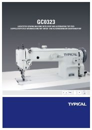
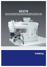
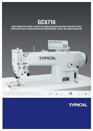
TW1-<strong>1245</strong>INSTRUCTION BOOK // PARTS CATALOGUECOMPOUND FEED LOCKSTITCH SEWING MACHINE
CONTENTSOperation instruction1. Brief intuoduction¡¡¡¡¡¡¡¡¡¡¡¡¡¡¡¡¡12. Main technical specifications¡¡¡¡¡¡¡¡¡¡¡¡¡¡13. Feed adjustment/reverse stitching¡¡¡¡¡¡¡¡¡¡¡¡¡14. Adjusting upper <strong>feed</strong> stroke¡ ¡ ¡ ¡ ¡ ¡ ¡ ¡ ¡ ¡ 1¡ ¡ ¡5. Winding bobbin thread¡¡¡¡¡¡¡¡¡¡¡¡¡¡¡¡26. Adjusting the bobbin thread tension¡ ¡ ¡ ¡ ¡ ¡ ¡ ¡ 2¡ ¡ ¡7. Threading the needle thread/adjusting the tension of needle thread¡¡¡¡¡¡¡28. Maintenance¡ ¡ ¡ ¡ ¡ ¡ ¡ ¡ ¡ ¡ ¡ ¡ ¡ ¡ 3¡ ¡ ¡ 9. Oiling¡ ¡ ¡ ¡ ¡ ¡ ¡ ¡ ¡ ¡ ¡ ¡ ¡ ¡ ¡ ¡ 3 ¡ ¡ ¡10. Lubricating the hook¡ ¡ ¡ ¡ ¡ ¡ ¡ ¡ ¡ ¡ ¡ ¡ 4¡ ¡ ¡ 11. Lubricating the <strong>machine</strong> head¡ ¡ ¡ ¡ ¡ ¡ ¡ ¡ ¡ ¡ 4¡ ¡ ¡ 12. Lubricating upper <strong>feed</strong> driving eccentric¡ ¡ ¡ ¡ ¡ ¡ ¡ 4¡ ¡ ¡13. Adjusting the <strong>feed</strong> dog¡ ¡ ¡ ¡ ¡ ¡ ¡ ¡ ¡ ¡ 5¡ ¡ ¡14. Pre-adjusting the needle height¡ ¡ ¡ ¡ ¡ ¡ ¡ ¡ ¡ ¡ 6¡ ¡ ¡ 15. Centering the needle in the needle hole¡¡¡¡¡¡¡¡¡¡¡¡616. Adjusting the bottom <strong>feed</strong> dog position¡¡¡¡¡¡¡¡¡¡¡¡617. Adjusting the upper and the lower <strong>feed</strong>¡ ¡ ¡ ¡ ¡ ¡ ¡ ¡ 7¡ ¡ ¡ 18. Position of needle and rotating hook¡ ¡ ¡ ¡ ¡ ¡ ¡ ¡ 7¡ ¡ ¡19. Adjusting the lifting amount of alternating presser foot. ¡ ¡ ¡ ¡ ¡ 7¡ ¡ ¡ 20. Top <strong>feed</strong> adjustment¡¡¡¡¡¡¡¡¡¡¡¡¡¡¡¡821. Adjusting the bobbin case opener¡¡¡¡¡¡¡¡¡¡¡¡¡822. Safety clutch¡ ¡ ¡ ¡ ¡ ¡ ¡ ¡ ¡ ¡ ¡ ¡ ¡ 8¡ ¡ ¡23. Needle thread tension release¡ ¡ ¡ ¡ ¡ ¡ ¡ ¡ ¡ ¡ 9¡ ¡ ¡ 24. Bobbin thread winder¡ ¡ ¡ ¡ ¡ ¡ ¡ ¡ ¡ ¡ ¡ ¡ 9¡ ¡ ¡ Parts manual1.Machine casting components¡¡¡¡¡¡¡¡¡¡¡¡¡¡¡¡¡¡¡¡10-112.Needle and presser foot components¡¡¡¡¡¡¡¡¡¡¡¡¡¡¡¡12-153.Presser foot lifting components¡¡¡¡¡¡¡¡¡¡¡¡¡¡¡¡¡¡¡¡16-174.Thread take-up and thread tension components¡¡¡¡¡¡¡¡¡¡¡¡18-195.Feed adjustment components¡¡¡¡¡¡¡¡¡¡¡¡¡¡¡¡¡¡¡¡20-216.Upper shaft and rocking shaft components¡¡¡¡¡¡¡¡¡¡¡¡¡¡¡¡22-237.Timing belt components¡¡¡¡¡¡¡¡¡¡¡¡¡¡¡¡¡¡¡¡24-258.Rotating hook saddle components¡¡¡¡¡¡¡¡¡¡¡¡¡¡¡¡¡¡¡¡26-279.Needle plate and hook components¡¡¡¡¡¡¡¡¡¡¡¡¡¡¡¡¡¡28-2910.Lower <strong>feed</strong> components¡¡¡¡¡¡¡¡¡¡¡¡¡¡¡¡¡¡¡¡30-3111.Lower shaft components¡¡¡¡¡¡¡¡¡¡¡¡¡¡¡¡¡¡¡¡32-3312.Knee lifter components¡¡¡¡¡¡¡¡¡¡¡¡¡¡¡¡¡¡¡¡34-3513. Binder Components¡¡¡¡¡¡¡¡¡¡¡¡¡¡¡¡¡8-3914. Accessories¡ ¡ ¡ ¡ ¡ ¡ ¡ ¡ ¡ ¡ ¡ ¡ ¡ 8¡ 39 ¡ ¡
OPERATION INSTRUCTION
1. Brief introduction2. Main technical specificationsTW1-<strong>1245</strong> adopts <strong>compound</strong> <strong>feed</strong> mechanism withsynchronous top, bottom and needle <strong>feed</strong> and themax amount of alternating presser foot lifter reaches7 mm, which guarantees the high <strong>sewing</strong> quality ofdifferent materials. Besides, TW1-<strong>1245</strong> adopts thelarge auto-lubricating horizontal rotating hook,4-link thread take-up lever and timing belt, whichassures its lower noise and high speed.This <strong>machine</strong> is widely used in manufacturingsuitcase, tents, cushions, lenther products, clothesbamboo matting, etc.ApplicationsMax. Sewing speedMax. Stitch lengthNeedle bar strokeNeedleLubricationMotor powerMedium &heavy weightmaterials2000s.p.m8mm36mmDP 35 80 140NmBy hand(partly)370W3. Feed adjustment/reverse stitching(Fig.1)11. Adjusting the stitch length by turning Nut 1;2. When backward stitching, push Nut 1to Mark Ras much as possible.4. Adjusting upper <strong>feed</strong> stroke(Fig.2)2Open the rear cover 1; loosen the screw2, and asrequired, move it up and down.1
3 5. Winding bobbin thread(Fig.3)1. Put the bobbin into the bobbin shaft 2;2. As Fig 3 shows, draw out the thread and windingclockwise to the bobbin several times;3. Before winding, press down the winding shaft 2and the hook gib 3;4. Adjusting the bobbin 1 thread tension by thescrew 4;5. When he bobbin is full, the bobbin winder willautomatically stop.If the winding is abnormal, loosen the screw 5,and as required, move the thread guide 6, thentighten the screw 5.46. Adjusting the bobbin thread tension(Fig.4)1. As Fig.4 shows, draw out the bobbin thread;When the bobbin thread is drawn out, thebobbin should run as the arrow goes.2. Adjusting the bobbin thread tension by thescrew 1.57. Threading the needle thread/adjusting the tension of needle thread(Fig.5)1. Threading as the Fig 5 shows.Pass the thread to the eye of needle from theleft side(Fig.arrow)2. Adjusting the needle thread tension by thescrew 12
8. MaintenanceClean the bobbin clearanceNormal oilingFront parts oilingCheck the hook oil boxClean the rotating hookUpper <strong>feed</strong> driving eccentric oilingOnce a weekTwice a weekTwice a weekOnce a weekOnce a weekonce a yearThe above data is due to the normal situation.If the <strong>machine</strong> is used frequently, the interval of themaintenance should be shortened.Maintenance for rotating hook(Fig.6)1. Clean the rotating hook with brush every day,and constant use needs more frequent cleansing.2. Clean the rotating hook thoroughly every week.As follows:a. Open the slide plate and lift the needle bar to itshighest point;b. Take out the bobbin cap and the bobbin;c. Release the hook gib 1; turn over the balancewheel until the Point 2 passes to the groove 5mm;then take out the bobbin case;d. Clean the rotating hook track with paraffinwax;e. When the bobbin case is installed, the horn 5and needle plate groove must be closely touched;(Fig. Arrow)Tighten the hook gib 1, install the bobbin caseand close the slide plate.679. Oiling(Fig.7)The <strong>machine</strong> must be oiled at the mark(arrow)twice a week.3
810. Lubricating the hook(Fig.8)1. Pull out the knee lever, then lay down the<strong>machine</strong> head;2. Fill the oil into box 1 through the hole 2 untilthe oil level exceeds the highest level mark;3. Raise the <strong>machine</strong>.911. Lubricating the <strong>machine</strong> head (Fig.9)1. Open the face plate;2. Oil twice a week at all the moving position asthe Fig shows;3. Close the face plate.1012. Lubricating the upper <strong>feed</strong> driving eccentric(Fig.10)1. Open the rear cover 1;2. Oil the interface (2) at least twice a year;(apply to oil gun)3. Close the rear cover.4
13. Adjusting the <strong>feed</strong> dog111. Positioning the <strong>feed</strong> dog across the direction of<strong>sewing</strong>(Fig.11);a. Loosen the screw 1 and 2;b. Adjust the shaft 3 as required;c. Tighten the screw 1. (Keep the screw 2 looseningfor the following adjustment)The bottom <strong>feed</strong> dog must be the same distancefrom the left and right side of the needle plate cutout2. Positioning the <strong>feed</strong> dog in the direction of <strong>sewing</strong>(Fig. 12)a. Set the longest stitchb. Adjust the shaft 1 as required, and tighten thescrew 2.With the longest stitch set, the bottom <strong>feed</strong> dogmust have the same clearance the front and the backwith respect to the needle plate cutout when <strong>feed</strong>ingboth forwards and backwards.123. Adjusting the height of <strong>feed</strong> dog (Fig.13)a. Adjust the stitch length to 0 ;b. Turn over the balance wheel until the <strong>feed</strong> dogreaches its highest position; and as required, adjust the<strong>feed</strong> dog supporter 1 and the screw 2.135
1414. Pre-adjusting the needle height(Fig.14)Move the needle bar 1 (screw2) up and down, andas required, adjust it to the right position.When the needle bar is at the lowest position,theclearance between needle bar and needle plate shouldbe 15 cm.1515. Centering the needle in the needle hole(Fig.15)1. Loosen the walking foot 1 and the presser foot 2;2. Adjust the stitch length to 0 , and lift theneedle bar to its highest point;3. Insert the new needle, and loosen the screw 3,4,5,6;4. Turn the balance wheel and pass the needledirectly through the <strong>feed</strong> dog;5. As required, move the needle bar frame 7;6. Tighten screw 3,4,5,;7. Move the pin 8 to make it touch the needle barframe 7, and tighten screw6.When the stitch length is at the 0 ,the needlemust enter the needle hole exactly in the middle1616. Adjusting the bottom <strong>feed</strong> dog position(Fig.16)1. Adjust the needle bar to the lowest position;2. Turn the eccentric wheel 1(screw 2) , and adjustthe bottom <strong>feed</strong> dog to the highest position;3. Tighten screw 2 to make the eccentric wheel 1unable to turn;4. Set the stitch length to the max and turn theeccentric wheel 1 a bit in accordance withrequirement 25. Tighten screw (2).a. When the needle bar is at its lowest position,the bottom <strong>feed</strong> dog should be at the highest position;Set the stitch length to its max; turn the balancewheel, and when t he bottom <strong>feed</strong> dog and the needleplate are in the same horixzontal level, the point ofthe needle should be right reaching the surface ofthe needle plate.6
17. Adjusting the upper and the lower <strong>feed</strong> (Fig.17)171. Adjust the stitch length to the max;2. Loosen screw 1 to make the <strong>feed</strong> eccentricwheel 2 turn around the shaft;3. Adjust the needle bar to the lowest position;4. Turn the eccentric wheel 2 so that its eccentricityis facing downwards.5. As required, turn the eccentric wheel a bit as itturns and tighten screw 1;6. Check it as required.When the stitch lenght is at the max, the needlebar is at the lowest positon, if the reverse <strong>feed</strong> leveris activated, there will be no <strong>feed</strong>ing.18. Position of needle and rotating hook(Fig.18)1. Adjust the stitch length to 3 , and loosenscrew 1,2;2. The clearance between needle and the hookpoint should be adjusted to 0.05-0.1 mm by movingthe hook gear 4;3. Tighten screw 1;4. Turn the needle to the lowest position, andcontinue to turn the hand wheel to raise 2 mm of theneedle;5. Make the hook point aim at the center,of theneedle and be sure the guard plate 7 doesn t press onthe needle;6. Leave some gear clearance and tighten screw 2;7. The vertical clearance between the top ofneedle eye and the hook point should be 0.8-1 mmby adjusting the needle height;8. The guard plate 8 might be adjusted to touchthe needle lightly.When the stitch length is adjusted to 3 andthe needle is lifted 2 mm from the lowest position,the follwing requirements must be reached:a. The clearance between needle and hook pointis 0.05-1mm;b. The vertical clearance between the top ofneedle eye and hook point is 0.8-1mm;c. The guard plate must touch the needle lightly.181919. Adjusting the lifting amount of alternating presser foot(Fig.19)1. The stitch length is adjusted to 0 , and thelifting amount of alternating presser foot is adjustedto the max;2. Lower the presser foot 1 on the needle plate;3. Turn the hand wheel until the walking foot 2reaches the highest position;4. As required, move the crank 3 (screw4);5. Check as required.When the stitch length is at the 0 and thelifting amount of alternating presser foot is at themax, turn the hand wheel to make sure the clearacebetween presser foot 1/ walking foot 2 and needleplate is 7mm .7
2020. Top <strong>feed</strong> adjustment (Fig.20)1. Lower the presser foot on the needle plate;2. Loosen screw 2 until the <strong>feed</strong> lifting eccentricwheel 3 can turn reluctantly;3. Adjust the eccentric wheel 3 as required;4. Tighten screw 2;5. Check as required.When presser foot is resting on the needle plate,the walking foot and the point of needle must bothreach the needle plate at the same time when the top<strong>feed</strong> stroke is set at maximum.2121. Adjusting the bobbin case opener1. Thread the <strong>machine</strong>; lay down the material; thenlower the presser foot;2. Turn the hand wheel and sew a bit, then check asrequired.3. Move the opener 1 (screw 2) as requiredThe needle thread must not be clamped whenpassing through the mark 1,3,42222. Saftety clutch (Fig.22)1. When the rotating hook jams the thread, thesafety clutch will be off to prevert the hook beingdamaged2. Take out the jammed thread;Press the piston 1 and turn the hand wheel untilhook 3 of pawl 2 clicks into groove 48
23. Needle thread tension release (Fig.23)23When the presser foot is lifted, the clearancebetween the two tension discs should be 0.5mm( 0.5mm is the minimum. When applied to thickthread, it could be adjusted to 1 mm or more).Adjustthe plate 1 as required.24. Bobbin thread winder (Fig.24)181. When the winder switch on, its spindle mustengage reliable; when the winder switch off, thefriction wheel 5 and the driving gear 1 should getapart;2. When the thread level is approx. 1mm from theedg of the bobbin, the winder will switch offautomatically;When operating, set the bobbin on the winder,threading the bobbin thread and switch the winderOn, adjust the pin 3 and screw 4 as requirementsif need.9
PARTSMANUAL
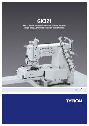
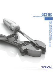
1.Machine casting components10
1.Machine casting componentsNo . Parts No . Name Qty. Remarks171WF2-001Arm1271WF2-002Bed1371WF2-003Face plate14Screw2571WF2-004Rear cover(left)1671WF2-005Rear cover(right)17Screw8871WF2-006Cover(small)1971WF2-007Screw(1)110Spring111Screw(2)1GB65-M5¡Á161271WF2-008Thread take-up lever guard113Screw11471WF2-009Front cover1GB67-M5¡Á815Screw21671WF5-005Safety guard(1)11771WF5-006Safety guard( 2)1GB1972-8018Set Screw4GB67-M4¡Á61971WF2-025Plug22071WF5-007Oil pan1GB67-M5¡Á82171WF5-008Washer622Screw6GB67-M5¡Á82371WF2-010Oil box set bracket complete124Washer225Screw2GB70-85 M5¡Á3526Washer227Screw211GB845 ST2.9¡Á19-C-Z
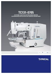
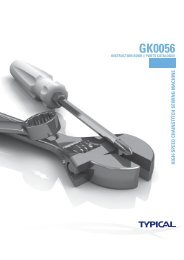
2.Needle and presser foot components4142434445464748495051525354555657585960616263646566676869 70 1234567891011121314151617181920212223242526272829303132333435363738394063
2.Needle and presser foot componentsNo . Parts No . NameQty. Remarks1234567891011121314151617181920212223242526272829303132333435363738394071WF4-00171WF4-00271WF4-00371WF4-00471WF4-00519WF1-013B71WF4-00671WF4-00771WF4-00871WF4-00971WF4-01071WF4-01171WF4-01271WF4-01371WF4-01471WF4-01571WF3-00371WF3-00471WF3-00571WF3-00613WF1-02971WF3-00771WF3-00871WF3-01571WF3-01671WF3-01771WF3-01871WF3-01971WF3-02071WF3-02171WF3-02271WF3-02371WF3-024Presser foot barPresser footPresser foot bracketScrewCollarScrewScrewSpring(big)Spring(small)Spring bushingGuide barOil feltSliding guideSet plateScrewWasherScrewPresser foot lifting barLifting bar shaftNeedle bar rocking frameOil feltHinge pinScrewCollarScrewPinSpringScrewWalking foot barWalking footScrewUpper <strong>feed</strong> bushingBearingStop ringScrewWasherWasher(front)Washer(rear)Upper <strong>feed</strong> shaftUpper <strong>feed</strong> crank(I)1111111111111122211111112111111224221111M15¡Á1GB65-M4¡Á10GB97.1-4GB70-M5¡Á10GB77-M6¡Á8M3¡Á3GB77-M5¡Á8SM17/64"¡Á28¦Õ10¡Á¦Õ13¡Á9.7GB77-M6¡Á513
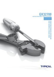
144142434445464748495051525354555657585960616263646566676869 70 12345678910111213141516171819202122232425262728293031323334353637383940632.Needle and presser foot components
2.Needle and presser foot componentsNo . Parts No . NameQty. Remarks41Screw24271WF3-025Presser foot lifting link14371WF3-026Link pin144Bearing14546474849505152535471WF3-02771WF3-02871WF3-02971WF3-03071WF3-03171WF3-032SpringPin(long)Upper <strong>feed</strong> crank(II)ShaftScrewBearingWasherSpringUpper <strong>feed</strong> crank( III)631112211GB65-M5¡Á12¦Õ5 ¡Á¦Õ 8¡Á7.7GB894.1-555Shaft156Screw157585971WF3-03371WF3-034BearingWasherSpring211GB77-M6¡Á8¦Õ6 ¡Á¦Õ9¡Á7.7606171WF3-03571WF3-036Movable plateLink11GB894.1-662636465666768697071WF3-03771WF3-03871WF3-03971WF2-02271WF2-02371WF2-024Presser foot linkPin(short)Slide blockSliding guideScrewFinger guardScrewFinger guard set plateScrew211121212GB77-M6¡Á8¦Õ7 ¡Á¦Õ10¡Á7.5GB894.1-7Washer215GB65-M4¡Á8
3.Presser foot lifting components31272919 2030272871816 1735 323634242325 2621332261541211813 14135109216
3.Presser foot lifting componentsNo . Parts No . NameQty. Remarks171WF1-001Needle bar1271WF1-002Needle bar thread guide1313WF1-015Screw14Needle1571WF1-003Screw1671WF4-016Knee lifter lever1771WF4-017Screw1871WF4-018Spring1971WF4-019Knee lifter drawing bar11011121371WF4-02071WF4-02171WF4-022NutConnectorScrewMovable plate complete1111M3¡Á5DP¡Á35 LRM3¡Á51471WF4-023Screw11571WF4-024Washer11671WF4-039Presser foot lift bent bar1171871WF4-040Releasing bent barScrew13GB6170-M51971WF3-040Presser foot lift cam12013WF1-018Screw22171WF3-041Link122Bearing12371WF3-042Stop ring224Oil cup12571WF3-043Pin12671WF3-044Washer1272871WF3-045WasherScrew(front)21M6¡Á0.75293071WF3-046Screw(rear)Adjusting crank11¦Õ22¡Á¦Õ26¡Á12.6313271WF3-083ScrewBlock21GB1152-89 M63371WF3-084Set bracket134Screw23536ScrewWasher22GB5781-M5¡Á8GB5781-M5¡Á1017GB65-M5¡Á12
4.Thread take-up and thread tension components566541718119 10 1287201914151316321 22484121475123 2450465449403438392842434445555352273633323135302937252618
4.Thread take-up and thread tension componentsNo . Parts No . NameQty. Remarks123456789101112131415161718192021222324252627282930313233343536373839404142434445464748495051525354555671WF1-00471WF1-00571WF1-00671WF1-00771WF1-008A71WF1-008B71WF1-008C71WF1-008D71WF1-008E71WF1-008F71WF1-00771WF1-00971WF1-01071WF1-01171WF2-01171WF2-01271WF2-01371WF2-01671WF2-021A71WF2-021B71WF2-021C71WF2-021D71WF2-021E71WF2-021F71WF2-021G71WF2-021H71WF2-021I71WF2-021J71WF2-021K71WF2-021L71WF2-021M71WF2-021N71WF2-021O71WF2-021P71WF2-021Q71WF2-021R71WF2-02271WF4-03371WF4-03471WF4-03571WF4-03671WF4-03771WF3-05371WF2-026Needle bar connectorScrewOil wickPin shaftScrewOil wickScrewCrankStudWasherThread take-up leverLink bushingBearing bushingScrewBearingHinge shaftOil wickPlugNeedle bar linkBearingThread guide(middle)Thread guide(lower)ScrewScrewStop plateScrewSet plateBoltNutStop washerSpringThread releasing discThread tension discThread take-up springThread control plate assemblyBoltScrewThread guide pinThread releasing pinThread releasing plateScrewSpringThread tension capThread tension discPinScrewThread releasing bracket assemblyScrewThread releasing barSpringScrewThread releasing leverSpring plateLever studSplit ringOil pipe11111111111111111111111111112111211112112111111111211112M4¡Á10GB77-M6¡Á8¦Õ7 ¡ ¦Õ10Á 7.5 ¡ Á¦Õ9 ¡ ¦Õ12Á 12.7 ¡ ÁM5¡ 7 ÁGB68-M4¡ 8 ÁGB65-M4¡Á6GB77-M5¡Á8SM9/64"¡Á40GB73-M4¡Á8GB67-M4¡Á1019M5¡ 6 Á
5.Feed adjustment components30313233123461020921121178221352324191825171628271415292620
5.Feed adjustment componentsNo . Parts No . NameQty. Remarks171WF3-047Feed cam1222T2-005B3Screw2371WF3-048Feed crank14Screw2571WF3-049Link stud16Screw1771WF3-050Stitch length label18Screw291071WF3-051Stitch length bracketScrew12SM1/4"¡Á40111271WF3-05271WF3-053Stitch length adjusting bracketStud11GB70-M5¡Á12131471WF3-05471WF3-055Stop bushingAdjusting bar11GB77-M4¡Á5151671WF3-05671WF3-057SpringScrew11GB68-M3¡Á8171871WF3-058WasherNut11GB70-M6¡Á161971WF3-059Sliding shaft120Oil wick12171WF1-013Filter12271WF3-060Screw12371WF3-061Sliding guide12471WF3-062Link1252671WF3-06371WF3-064SpringSpring hook11GB6172-86 M627Screw12871WF3-013Crank stud12971WF3-014Nut13071WF2-027Oil tube31Oil wick3271WF2-028Oil tube33Oil wickGB70-85 M6¡Á10SM17/64"¡Á2821
6.Upper shaft and rocking shaft components12151831916 1741412 1325231098221172452021286312729263022
6.Upper shaft and rocking shaft componentsNo . Parts No . NameQty. Remarks171WF2-029Oil plug1271WF2-030Oil plug1371WF2-027Oil pipe14Oil wick1571WF2-034Bobbin thread winder assembly16Screw1771WF2-035Friction wheel1813WF1-027Screw29Screw21071WF1-012Needle bar crank11171WF1-013Oil plug11271WF1-014Upper shaft11371WF1-015Washer1GB68-M4¡Á81471WF1-016Upper shaft bushing(front)115Oil wick1M6¡Á0.7516Screw1GB77-M6¡Á51771WF1-017Upper shaft bushing(middle)118Oil wick119Screw12071WF3-078Screw12171WF3-079Nut12271WF3-080Feed dog lift cam12371WF3-081Screw2GB77-M6¡Á82471WF3-082Feed dog lift link125Oil wick12671WF3-001Rocking shaft assembly1GB77-M6¡Á82771WF3-002Slide block12871WF3-009Rocking shaft driving cam1SM11/64"¡Á2829Screw13071WF3-010Rocking shaft link13171WF3-011Screw1GB70-M8¡Á1623SM17/64"¡Á32
7.Timing belt components23221319184215 8 7 6211021191716201315141224
7.Timing belt componentsNo . Parts No . NameQty. Remarks171WF2-014Thread guide bar assembly12Nut1371WF2-015AThread tension disc1471WF2-015BThread tension spring1571WF2-015CThread tension nut1671WF1-018Collar1719WF3-005Screw28Bearing191071WF1-019Timing pulley assemblyScrew11GB6170-M611Screw112Timing belt11371WF1-021ATension wheel114151671WF1-021BTension wheel bracketBearingScrew112M6¡Á0.756002-2ZNR 15¡Á32¡Á91718192071WF1-022WasherHand wheelScrewScrew2111GB78-M6¡Á0.75GB77-M6¡Á0.75270H0632171WF1-023Collar1222371WF1-024ScrewWasher116000-2ZGB70-M5¡Á12GB97.1-5GB78-M6¡Á0.75GB77-M6¡Á0.75GB68-M6¡Á2025
8.Rotating hook saddle components28727910852119121162920251413431516171211822623222426
8.Rotating hook saddle componentsNo . Parts No . NameQty. Remarks123456789101112131415161718192021222324252627282971WF1-02871WF1-03122WF4-00571WF1-03271WF1-03319WF3-00571WF1-03471WF1-03571WF1-03671WF1-03771WF1-03871WF1-03971WF1-04071WF1-04171WF1-04271WF1-04371WF1-04471WF1-04571WF1-04771WF1-04971WF1-06171WF1-06271WF2-030Lower shaft bushing(front)CollarScrewLower shaft gearRotating hook gearScrewHook openerAdjusting plate assemblyAdjusting screwRotating hook saddleScrewWasherOil felt(1)Oil felt(2)Screw barPinCover plateScrewJointOil pipeOil wickGear cover(1)Gear cover(2)ScrewOil boxOil hole coverRotating hook shaftScrewOil plug11211411112211111111111111111M5M6¡Á0.75GB65-M4¡Á8GB70-85 M6¡Á25GB879-86 1¡Á16GB65-M4¡Á8¦Õ3 L=400GB65-M4¡Á1427
9. Needle plate and hook components2431658791028
9. Needle plate and hook componentsNo . Parts No . NameQty. Remarks171WF2-017Needle plate1271WF2-018Screw2371WF2-019Slide plate(left)1471WF2-020Slide plate(right)1571WF3-070Feed dog16JO.O.50Screw27Rotating hook assembly18Bobbin cap191071WF1-04671WF1-060BobbinWasher11SM11/64"¡Á40SM1/8"¡Á44LRT1242-RSCP54529
10. Lower <strong>feed</strong> components64653310921847191218151620171513112122141330
10. Lower <strong>feed</strong> componentsNo . Parts No . NameQty. Remarks171WF3-012Feed shaft crank12Screw2371WF3-065Feed shaft set pin24Screw2571WF3-066Feed shaft16Oil wick2771WF3-067Feed dog supporter1871WF3-068Hinge pin1GB65-M5¡Á10971WF3-069Collar110111271WF3-07171WF3-065ScrewFeed dog lifting shaft set pin(front)Feed dog lifting shaft set pin(rear)211GB77-M6¡Á813Screw21471WF3-072Feed dog lifting shaft115Oil wick21671WF3-073Feed dog lifting cam1GB77-M5¡Á417Screw21871WF3-074Slide block11971WF3-075Screw1GB77-M6¡Á82071WF3-076Nut12171WF3-077Feed dog lifting shaft crank122Screw22377WF7-005Crank1GB65-M5¡Á122477WF7-006Pin125Screw1SM11/64"¡Á3231
11. Lower shaft components127201819111221 2223 24 25161526281317142486359 108732
11. Lower shaft componentsNo . Parts No . NameQty. Remarks171WF1-025Lower shaft(front)1271WF1-026Lower shaft(rear)1371WF1-027Timing pulley assembly14Screw15Screw1671WF1-029Lower shaft bushing(rear)17Screw18Bearing2971WF1-030Collar11013WF1-027Screw411121371WF1-050Saftety clutch bodyScrewScrew111GB78-M6¡Á0.75GB77-M6¡Á0.7514151671WF1-051Safety clutch camScrewScrew111GB77-M6¡Á8¦Õ10¡Á¦Õ13¡Á9.71771WF1-052Spring plate11871WF1-053Pin119202171WF1-054Split ringScrewStop pin121GB78-M6¡Á0.75GB77-M6¡Á0.7522232471WF1-05571WF1-056Split ringWasherSpring111GB78-M6¡Á0.75GB77-M6¡Á0.752571WF1-057Screw126272871WF1-05871WF1-059SpringSpring bushingScrew222GB896-86 4GB77-M5¡Á6GB896-86 3GB78-M6¡Á0.7533
12. Knee lifter components3874151091162151219161318141734
12. Knee lifter componentsNo . Parts No . NameQty. Remarks171WF4-025Knee lifter bar bracket12Screw3371WF4-026Washer3471WF4-027Knee lifter crank assembly15Spring2671WF4-028Spring1771WF4-029Knee lifter crank link1871WF4-030Screw1GB70-M8¡Á25971WF4-031Stop block110Screw111Nut1GB894.2-86 181271WF6-001Knee lifter shaft assembly11371WF6-002Knee lifter crank11422T9-003B4Screw21522T9-003B2Knee press bar11622T9-003B5Knee press plate1GB70-M6¡Á201722T9-003B6Knee press rod bracket1GB6170-M61822T9-003B7Screw11922T9-003B8Knee press plate pad1SM5/16"¡Á1835
13. Binder Components36
13. Binder ComponentsNo . Parts No . NameQty. Remarks1234567891077WF7-007A77WF7-007B77WF7-007C77WF7-00877WF7-00977WF7-01077WF7-011A77WF7-011B77WF7-011C77WF7-012BaseCoverNutSpringSpacerScrewSet platePinScrewBracket112111192137
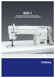
14. Accessories123457610911128131438
14. AccessoriesNo . Parts No . NameQty. Remarks12345678910111213144F-00733TF-0111F-00933TF-01333TF-0141F-01371WF5-00971WF5-01071WF5-011V-beltThread stand assemblyOil potOil tankScrewdriver(middle)Screwdriver(small)Machine head coverMachine head hingeCushionRubber padHexagonal wrenchHexagonal wrenchHexagonal wrenchHexagonal wrench11111112221111S=2.5mmS=3mmS=4mmS=5mm39
TW1-<strong>1245</strong>COMPOUND FEED LOCKSTITCH SEWING MACHINECertifi cate of theinternational ISO9001Certifi cate of theISO14001Certifi cate of theinternational CECertifi cate forEcolabelling ProductCertifi cate for EnergyConservation ProductXI´AN TYPICAL EUROPE GmbHHertelsbrunnenring 9D-67657 KaiserslauternTel.: +49 (0)631 316019-0Fax: +49 (0)631 316019-11E-mail: sales@typical-europe.comwww.typical-europe.comTW1-<strong>1245</strong> – Manual – EN – 10-2010