EFIS-D60 Installation Guide - Dynon Avionics
EFIS-D60 Installation Guide - Dynon Avionics
EFIS-D60 Installation Guide - Dynon Avionics

You also want an ePaper? Increase the reach of your titles
YUMPU automatically turns print PDFs into web optimized ePapers that Google loves.
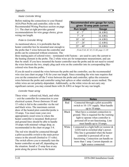
AppendixHeater Controller WiringBefore making the connections to your HeatedAOA/Pitot Probe and controller, refer to theRecommended Wiring Practices section on page2-1. The chart at right provides generalrecommendations for wire gauge choice, givenwiring run length.Probe to Controller WiringAs mentioned above, it is preferable that theheater controller box be mounted near enough tothe probe that 5 wires between the controller andprobe can be connected without extension. TheRecommended wire gauge for runs,given 10-amp peak currentRun length Gauge0’ – 7’ 18 AWG7’ – 9’ 16 AWG10’ – 16’ 14 AWG17’ – 24’ 12 AWG25’ – 40’ 10 AWGFrom FAA AC 43.13-1B, page 11-30three mating pairs of colored wires – terminated with Fastons – are used to carry the current tothe heating element in the probe. The 2 white wires are for temperature measurement, and canthus be small. If you have mounted the heater controller near the probe and do not need to extendthe wires between the two, simply plug each wire on the controller into its corresponding likecoloredwire from the probe.If you do need to extend the wires between the probe and the controller, use the recommendedwire size (see chart on page 5-8) for your run length. Since extending the wire runs requires thatyou cut the connectors off the 5 wires between the probe and controller, splice the extensionwires between the probe and controller using butt splices or other similarly secure method. Thewhite wires are not polarity-dependant. Additionally, as the white wires do not carry anysignificant current, you may extend them with 26 AWG or larger for any run length.Controller Power wiringThree wires – colored red, black, and white– exit the controller for connection to yourelectrical system. Power (between 10 and15 volts) is fed to the controller via the redand black wires. The maximum currentdraw of the heated pitot controller/probe is10 amps. You must route your ownappropriately-sized wires to where theheater controller is mounted. Both powerand ground lines should be able to handle10 amps with minimal voltage drop, asrecommended in the chart on page 5-8.The red wire should be connected througha pilot-accessible switch to the main powersource in the aircraft (limited to 15 volts).The switch allows you to manually turn theheater controller on and off, depending onthe situation. Install a 15-amp fuse at anypoint along the power line to the heaterColorRedBlackWhiteNotesConnected through a pilot-accessibleswitch to 10–15V supply. Must handleup to 10 amps.Must have a constant connection toground. This is required for the warninglight to operate when controller ispowered off or not functioning. Linemust handle up to 10 amps.Connected to a light bulb (or resistor &LED) tied to switched ship’s power.This line is grounded when the heatercontroller is powered off or notfunctioning. Connection can handle nomore than 1 amp. Current depends onlight source connected.5-10 <strong>EFIS</strong>-<strong>D60</strong> <strong>Installation</strong> <strong>Guide</strong>