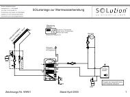
Pr - Solution Solartechnik GmbH
Pr - Solution Solartechnik GmbH
Pr - Solution Solartechnik GmbH

You also want an ePaper? Increase the reach of your titles
YUMPU automatically turns print PDFs into web optimized ePapers that Google loves.
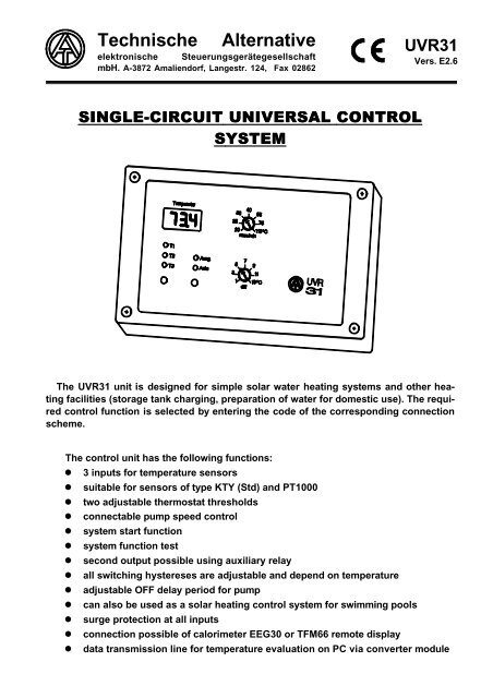
Technische Alternative<br />
elektronische Steuerungsgerätegesellschaft<br />
mbH. A-3872 Amaliendorf, Langestr. 124, Fax 02862<br />
aal<br />
SINGLE-CIRCUIT UNIVERSAL CONTROL<br />
SYSTEM YSTEM<br />
The UVR31 unit is designed for simple solar water heating systems and other heating<br />
facilities (storage tank charging, preparation of water for domestic use). The required<br />
control function is selected by entering the code of the corresponding connection<br />
scheme.<br />
The control unit has the following functions:<br />
� 3 inputs for temperature sensors<br />
� suitable for sensors of type KTY (Std) and PT1000<br />
� two adjustable thermostat thresholds<br />
� connectable pump speed control<br />
� system start function<br />
� system function test<br />
� second output possible using auxiliary relay<br />
� all switching hystereses are adjustable and depend on temperature<br />
� adjustable OFF delay period for pump<br />
� can also be used as a solar heating control system for swimming pools<br />
� surge protection at all inputs<br />
� connection possible of calorimeter EEG30 or TFM66 remote display<br />
UVR31<br />
Vers. E2.6<br />
� data transmission line for temperature evaluation on PC via converter module
PLEASE NOTE:<br />
The hydraulic diagrams shown in this booklet represent schematic<br />
drawings. In no way do they describe or replace specialist systems<br />
planning, which is why their functioning cannot be guaranteed even if<br />
copied directly.
Contents:<br />
General 4<br />
Introduction 4<br />
Control panel 4<br />
Hydraulic diagrams 5<br />
Diagram 0 - simple solar water heating system 5<br />
Diagram 16 - charge pump control 6<br />
Diagram 32 - burner control system 7<br />
Diagram 48 - speed-controlled generation of warm water<br />
with external heat exchanger 8<br />
Installation 9<br />
Sensor installation 9<br />
Installation of the device 11<br />
Electrical connection 11<br />
Data transmission line 12<br />
Auxiliary relay (HiRel) 13<br />
Additional functions 14<br />
What does the setting mode contain? 14<br />
<strong>Pr</strong>ogramming diagram of UVR31 control system 15<br />
Sensor type 16<br />
Overtemperature limitation 17<br />
Start function 18<br />
OFF delay period for pump 19<br />
Hystereses 19<br />
Speed control 20<br />
<strong>Pr</strong>ogramming diagram of speed processor 23<br />
Appendix 24<br />
Table of settings 24<br />
Technical data 25<br />
Scope of supply 25<br />
In the event of malfunctioning 26<br />
Maintenance 27<br />
Safety regulations 27
General<br />
Introduction<br />
The following pages show diagrams indicating the assignment of sensors, pumps and<br />
settings as well as corresponding program numbers.<br />
To enter these numbers, the temperature selector key must be pressed for two seconds.<br />
Three small lamps (T1 - T3) light up to show that setting mode has been selected. The program<br />
number now appears in the display (e.g. P24). The required number can be set with<br />
the output key. Depress the temperature selector key again for two seconds to terminate<br />
input. The device then returns to normal operation.<br />
IMPORTANT: In setting mode, it is possible to switch to other settings. All these values<br />
have been set to a standard system in the factory. They generally do not have to be changed.<br />
As additional functions may change the properties of the control system entirely, they<br />
should be left to an expert.<br />
The factory setting (FS) can be restored at any time by pressing the temperature selector<br />
key while plugging in. After this, however, the program number has to be set.<br />
Control panel<br />
Using the output key, it is possible to change output status:<br />
Auto illuminated = automatic mode - output indicates mode<br />
Auto dark = manual mode - output indicates continuous operation or stopping<br />
diff1: The differential temperature is the amount by which the energy generator (e.g. solar<br />
collector) has to become hotter than the consumer unit (e.g. hot water tank) for the<br />
pump to run. Normally a value between 5 and 10°C is selected. This is largely influenced<br />
by tube length, insulation, sensor installation and the consumer unit. Hysteresis<br />
has an upward effect, i.e. on reaching differential temperature plus hysteresis<br />
temperature, the pump motor is switched on and on falling below the differential it is<br />
switched off.<br />
Depending on the selected diagram, one of the following two functions results:<br />
max/: The maximal thermostat function limits storage tank charge as a protection against<br />
calcification, destruction of tank coating, scalding, etc. Hysteresis has a downward<br />
effect, i.e. switchoff on reaching threshold temperature and switchon on falling below<br />
threshold temperature less hysteresis temperature.<br />
min: The minimal threshold is provided to protect against boiler sooting. It should be between<br />
60 - 70 °C. Its assignment to a circuit depends on the selected diagram. Hysteresis<br />
has an upward effect, i.e. switchon when threshold temperature plus hysteresis<br />
temperature is reached and switchoff on falling below threshold temperature.<br />
Int C: This function (additional thermostat threshold) can only be reached via the programming<br />
level (see program selection). Depending on the program selected, this value<br />
also acts as a max or min threshold.<br />
4
Hydraulic diagrams<br />
The auxiliary relay HiRel which is repeatedly mentioned in the following pages is a module<br />
which is obtainable as a special accessory and can be integrated into the device, allowing a<br />
second (auxiliary) output to be set up.<br />
Diagram 0: Simple solar water heating system FS = program 0<br />
Sensor:<br />
T1....... collector<br />
T2....... lower part of storage tank<br />
T3....... freely usable<br />
Required settings:<br />
diff....... collector T1 - storage tank T2<br />
max..... limitation - storage tank T2<br />
int C.... see programs 2 to 5<br />
<strong>Pr</strong>ogram 0: Output A1 works according to the diagram. When a fault occurs, the auxiliary<br />
relay (HiRel - special accessory) switches to sensor fault or too high a temperature differential,<br />
depending on the function test. Furthermore, when a fault occurs, an error code is displayed<br />
every second alternately to the usual readout.<br />
Error codes are discribed on page 26 - In the event of malfunctioning.<br />
<strong>Pr</strong>ogram 1: By installing sensor T3 on the solar feed line, an additional function control is<br />
possible for circulation problems.<br />
<strong>Pr</strong>ogram 2: The auxiliary relay switches when T2 exceeds threshold C.<br />
<strong>Pr</strong>ogram 3: The auxiliary relay switches when T3 exceeds threshold C.<br />
<strong>Pr</strong>ogram 4: A1 is given an additional minimum threshold at T1 with C.<br />
<strong>Pr</strong>ogram 5: A1 is given an additional minimum threshold at T3 with C.<br />
<strong>Pr</strong>ogram 8: Bypass function - the auxiliary relay switches a bypass valve if (feed) sensor T3<br />
is higher than T2 by diff and solar pump A1 is running.<br />
<strong>Pr</strong>ogram 9: A1 switches if T1 (radiation sensor - special accessory) exceeds the minimum<br />
threshold C and T2 is below max. Bypass function - the auxiliary relay switches a bypass<br />
valve if (feed) sensor T3 is higher than T2 and T2 is below max.<br />
<strong>Pr</strong>ogram 10: A1 has the same function as <strong>Pr</strong>ogramm 9. Bypass function - the auxiliary relay<br />
switches a bypass valve if (feed) sensor T3 is higher than T2 and A1 ist active.<br />
Important: Regardless of the settings, the following holds: If T1 exceeds a set threshold of<br />
140 °C, output is blocked until T1 has fallen below 120 °C. This function can be found in the<br />
menu 'Utb' and can be changed or also deactivated there.<br />
5
Diagram 16: Storage tank charging from boiler.<br />
Sensor:<br />
T1....... boiler<br />
T2....... lower part of storage tank<br />
T3....... freely available<br />
Required settings:<br />
diff....... boiler T1 - storage tank T2<br />
min...... switch-on threshold - boiler T1<br />
Int C.... various functions acc. to prog.<br />
<strong>Pr</strong>ogram 16: A1 works according to the diagram. The auxiliary relay (HiRel - special accessory)<br />
allows a minimal thermostat function to be set up by T1 and C.<br />
<strong>Pr</strong>ogram 17: The auxiliary relay switches when T3 exceeds the minimum threshold C.<br />
<strong>Pr</strong>ogram 18: A1 is given an additional maximum limit with T2 and C.<br />
<strong>Pr</strong>ogram 19: A1 is given an additional maximum limit with T3 and C.<br />
<strong>Pr</strong>ogram 20: T3 sits in the return and the auxiliary relay is used for raising the temperature<br />
of the water in the return pipe. It switches when T1 > min & T3 < C.<br />
All programs +8: Storage tank charging from two sources (boiler). A1 also switches if T3 is<br />
higher than T2 by the differential.<br />
All programs +12: Storage tank charging from two sources as with +8 with additional minimum<br />
threshold, i.e. A1 also switches if T3 > C & (T3 + diff) > T2.<br />
6
Diagram 32: Burner request by means of two storage tank sensors.<br />
Sensor:<br />
T1........ boiler<br />
T2........ upper part of storage tank<br />
T3........ lower part of storage tank<br />
Required settings:<br />
max/min..switch-on threshold T2<br />
and switch-off threshold T3<br />
Int C....... various functions acc. to prog.<br />
<strong>Pr</strong>ogram 32: Function according to diagram. Request with max/min on T2 and switch off<br />
with the same threshold at T3. The auxiliary relay switches when T1 increases beyond<br />
threshold C.<br />
Important: For many applications, program 40 (32 + 8) is more suitable due to the zero-potential<br />
output of the auxiliary relay.<br />
<strong>Pr</strong>ogram 33: Request with max/min on T2 and switch off with threshold C on T2.<br />
<strong>Pr</strong>ogram 34: Request with max/min on T2 and switch off with threshold C on T3.<br />
<strong>Pr</strong>ogram 40: The auxiliary relay as a zero-potential contact receives the original function of<br />
the burner request from A1. Thus the standard output A1 can be used to control the charge<br />
pump.<br />
A1 switches if T1 > C & (T1 + diff) > T2<br />
<strong>Pr</strong>ogram 41: Combines the functions of programs 33 and 40. Request via the auxiliary relay<br />
with max/min at T2 and switch off with threshold C also at T2.<br />
A1 (charge pump) switches if T1 > 45°C & (T1 + diff) > T2<br />
<strong>Pr</strong>ogram 42: Combines the functions of programs 34 and 40. Request via the auxiliary relay<br />
with max/min at T2 and switch off with threshold C at T3.<br />
A1 (charge pump) switches if T1 > 45°C & (T1 + diff) > T2<br />
<strong>Pr</strong>ogram 44: The auxiliary relay as a zero-potential contact receives the original function of<br />
the burner request from A1. Thus the standard output A1 can be used to control the charge<br />
pump. Unlike program 40, comparison is made here with T3.<br />
A1 switches if T1 > C & (T1 + diff) > T3<br />
<strong>Pr</strong>ogram 45: Similar to the sum of programs 33 and 46. Request using the auxiliary relay<br />
with max/min at T2 and switch off with threshold C also at T2.<br />
A1 (charge pump) switches if T1 > 45°C & (T1 + diff) > T3<br />
<strong>Pr</strong>ogram 46: Similar to the sum of programs 34 and 46. Request using the auxiliary relay<br />
with max/min at T2 and switch off with threshold C at T3.<br />
A1 (charge pump) switches if T1 > 45°C & (T1 + diff) > T3<br />
7
Diagram 48: Speed-controlled generation of warm water with external heat exchanger<br />
Sensor:<br />
T1........ warm water<br />
T2........ flow switch STS01DC<br />
in cold water inlet<br />
T3........ top reservoir<br />
Required settings:<br />
diff...T1 - T2 (does not work through STS)<br />
max..... warm water limit T1<br />
recommended value: min. 80 °C<br />
Absolute and differential control active<br />
<strong>Pr</strong>ogram 48: The flow switch (STS01DC = special accessory) allows the control device to<br />
detect water depletion and switch on pump A1. T1 is then held constant at the input absolute<br />
value using the speed control device. If reservoir temperature T3 falls, the controller<br />
keeps the set difference between T3 and T1 constant (in speed control menu F31 u. d.) in<br />
order to prevent any mixing of the reservoir as a result of excessively high volume flow rates.<br />
<strong>Pr</strong>ogram 49: As program 48 but with a start function. If T1 falls below the internal threshold<br />
C and if T3 is over 50 °C, the pump runs until T1 has reached temperature C.<br />
IMPORTANT:<br />
Sensor T1 has to react quickly, which is why a special, high-speed sensor (BFS - special<br />
accessory) is required. A T-piece should be used to stand the sensor immersion sleeve in<br />
the heat exchanger outlet, in order to achieve a fast reaction.<br />
Furthermore in the 'speed processor' menu (Pdr), it is essential to adjust the PID controller<br />
according to the following procedure:<br />
With a system ready for operation and with the appropriate temperatures at the time of<br />
testing, the pump should run in automatic mode (water tap on).<br />
Setting A-1 and c50 (i.e. T1 is kept constant at 50 °C).<br />
While In and di are zeroed, the proportional part <strong>Pr</strong> is reduced every 30 seconds starting<br />
from 9 until the system becomes unstable, i.e. the pump speed changes rhythmically. This<br />
process can easily be observed in menu section n (= display of current output speed). The<br />
proportional part where instability starts is noted as <strong>Pr</strong>krit, while the duration of the vibration<br />
(= time between two top speeds in relation to n) is noted as tkrit. The following formulae<br />
allow the correct parameters to be determined:<br />
typical: 8 9 3<br />
With the computed values, the system will run in a largely stable manner.<br />
8<br />
<strong>Pr</strong> = 1, 6 % <strong>Pr</strong>krit In = tkrit % <strong>Pr</strong><br />
20<br />
di =<br />
<strong>Pr</strong> % 8<br />
tkrit
Installation<br />
Sensor installation:<br />
For the system to function correctly, it is very important that sensors are located and<br />
installed properly. Make absolutely sure that they are completely pushed into the immersion<br />
sleeves. The clip-on sensors must be well insulated in order to prevent them from being<br />
influenced by the ambient temperature.<br />
When used outdoors, no water should be allowed to get into the immersion sleeves (danger<br />
of frost). The sensors should generally not be exposed to moisture (e.g. condensation)<br />
as this can diffuse through the cast resin and damage the sensor. Heating at approx. 90 °C<br />
for one hour may possibly save the sensor.<br />
When used in NIRO storage tanks or swimming pools, make absolutely sure that immersion<br />
sleeves are corrosion-resistant.<br />
� Collector sensor (red cable): Either push into a tube which is soldered or riveted directly<br />
to the absorber and projects from the collector housing, or place a T-piece on the flow collecting<br />
tube of the outer collector, insert an immersion sleeve into this together with cable<br />
connection (=moisture protection) and push in the sensor. For vacuum tube collectors, use<br />
of PT1000 sensors is recommended.<br />
� Boiler sensor (boiler flow): This is either screwed into the boiler with an immersion<br />
sleeve or fitted to the flow pipe at a slight distance from the boiler.<br />
� Hot water tank sensor: In the case of ribbed pipe heat exchangers, the sensor required<br />
for the solar water heating system should be used with an immersion sleeve just above the<br />
exchanger and, with integrated bare tube heat exchangers, in the lower third of the exchanger<br />
or should be fitted at the exchanger's return outlet so that the immersion sleeve goes<br />
into the exchanger tube. The sensor which monitors hot water tank heating from the boiler<br />
is installed at the height corresponding to the required quantity of hot water in the heating<br />
period. In no way is installation permissible beneath the corresponding register or heat<br />
exchanger.<br />
� Storage tank sensor: The sensor required for the solar water heating system is installed<br />
in the lower part of the storage tank just above the solar heat exchanger with the help of the<br />
immersion sleeve supplied. As a reference sensor for heating hydraulics, it is advisable to<br />
insert the sensor with the immersion sleeve between the centre and top third of the storage<br />
tank, or push beneath the insulation - keeping close to the tank wall.<br />
� Pool sensor (swimming pool): Place a T-piece on the suction line directly at the pool<br />
outlet and screw in the sensor with an immersion sleeve (check corrosion resistance of the<br />
material used). Another possibility would be to attach the sensor at the same place by<br />
means of clips or adhesive tape, using appropriate thermal insulation against environmental<br />
influences.<br />
� Clip-on sensors: Best secured to the appropriate line with pipe clamps, clips, etc.<br />
whereby you must make sure that the material is suitable (non-corrosive, heat-proof, etc.).<br />
Finally, the sensor must be well insulated in order to measure pipe temperature accurately<br />
and to prevent any influence from ambient temperature.<br />
9
� Hot-water sensor: When the control unit is used in systems for generating hot-water by<br />
means of an external heat exchanger and a speed-controlled pump, a fast response to<br />
changes in water quantity is vital. This is why the hot-water sensor must be placed as close<br />
as possible to the heat exchanger outlet. Use a T-piece to insert the immersion sleeve into<br />
the outlet. Furthermore, use of a fast-response sensor is recommended (BFS - special<br />
accessory).<br />
Sensor lines with a diameter of 0.75 mm2 can be extended up to 50m and above this<br />
with 1.5 mm2. A connection between sensor and extension can be established as follows:<br />
Push the shrink-fit hose provided (halved to 4 cm) over one core, twist the bare wire ends<br />
firmly and then push the shrink-fit hose over the bare part and carefully warm up (e.g. with a<br />
cigarette lighter) until the hose fits tightly over the connection. This connection can then be<br />
drawn easily into the pipework.<br />
10
Installation of the device<br />
IMPORTANT! ALWAYS WITHDRAW PLUG FROM MAINS BEFORE OPENING THE<br />
HOUSING!<br />
Undo the four screws at the corners of the housing. The control electronics are located in<br />
the cover and are connected to the supply module situated in the housing trough by means<br />
of a flat cable. The housing trough can be screwed to the wall (with cable lead-ins downwards)<br />
through the two holes on the underside, using the fixings provided. The supply<br />
module can be removed from the trough to allow easier handling.<br />
Elektrical connection:<br />
This should only be done by a specialist according to relevant local guidelines. Sensor<br />
lines should never be routed together with the line voltage in one cable. When a cable<br />
duct is shared, suitable shielding must be ensured.<br />
Caution: Work inside the control system should only be done when deenergized. It is<br />
possible to damage the unit if it is assembled under voltage.<br />
All sensors and pumps or valves must be connected according to their numbering in the<br />
selected diagram.<br />
If required, the device is also supplied with a relay output. In this case, terminal Ö (K2) is<br />
connected with the break contact and K4 marks the make contact.<br />
11
All sensor earthing is interconnected internally and can be exchanged at random.<br />
Note: To protect against lightning damage, the system must be earthed according to<br />
regulations. Sensor failures due to the weather or electrostatic charging are mostly due to<br />
poor earthing.<br />
At the request of the customer, some devices are fitted with sockets on the left side of<br />
the housing. The lower socket is a parallel connection for the collector sensor. This allows<br />
the device to be wired to the storage tank in the factory, dispensing with any need to open<br />
up the device on-site.<br />
The upper socket is for the data transmission line (also connected parallel to the internal<br />
terminal) and allows easy connection of an interface converter module (UVS232 - special<br />
accessory) for service purposes or for troubleshooting.<br />
Data transmission line (DL)<br />
The data transmission line was specially developed for the series UVR and is only compatible<br />
with these products. Designed purely as an output line, it has the following use:<br />
�To connect remote display TFA6 or TFA66. This is necessary if indication of all temperatures<br />
at another location is also required. The data transmission line allows the remote display<br />
to be supplied with the necessary energy and data using a two-wire line (such as the<br />
sensor cable).<br />
�To connect calorimeter EEG30. This is thereby supplied with the required energy and<br />
receives the data for its integrated remote indication and the hours-run meter.<br />
�As interface to the personal computer via the usual serial input (RS 232) for entering temperatures<br />
measured. For this, converter module UVS 232 is necessary, which converts<br />
signals into a form corresponding to the RS 232 norm.<br />
12
Auxiliary relay (HiRel)<br />
The control system has a five-pin connector on the supply module and a retaining groove<br />
in the housing for subsequently fitting this additional relay module. This allows a switch<br />
contact to be provided in parallel to existing outputs.<br />
In order to achieve the required link with the corresponding outputs, the module has a pin<br />
connector with plug-in jumpers.<br />
It is irrelevant here whether one speed-controlled<br />
output of the control system is involved or several<br />
outputs at the same time.<br />
If A1 is connected, the relay also switches with<br />
the original output. Connecting A2 (as illustrated in<br />
the diagram alongside) results in an additional<br />
output of equal value.<br />
Usually the module is used:<br />
W.....root<br />
S...... make contact<br />
O......break contact<br />
� as additional output for a bypass valve<br />
� as a switch contact parallel to the (activated) speed output<br />
� as a zero-potential (deenergised) contact for the burner request<br />
To be correctly connected to the supply module of the control system, the flat cable must<br />
not be twisted.<br />
13
Additional functions<br />
A setting mode allows additional functions for optimising the solar water heating system<br />
or other heating facility. As these functions can change the properties of the control system<br />
fundamentally, they should only be dealt with by specialists or at least by persons who<br />
are sufficiently familiar with these instructions. It should also be noted that not every<br />
additional function is advisable for every program.<br />
�� Entry into setting mode (first menu level):<br />
If you press approx. two seconds on the yellow temperature selector key, the computer<br />
switches to setting mode. All temperature selection lamps (T1 - T3) are illuminated to indicate<br />
readiness for programming and the program number P.. appears in the display. This<br />
two-digit number is necessary for all basic control functions and has already been explained<br />
on page 3.<br />
�� Advancing:<br />
<strong>Pr</strong>ess the temperature selector key briefly to advance from one setting value to the next.<br />
�� Changing:<br />
<strong>Pr</strong>ess the output key once to increase the value. Hold it down to count upwards.<br />
�� To quit setting mode:<br />
To return to normal mode, press the temperature selector key again for at least two<br />
seconds in the displays Pxx, Cxx, Exx or End. The system also returns to normal mode<br />
within one minute if no key is pressed.<br />
�� Restoring factory setting (FS):<br />
The factory setting can be restored by pressing the temperature selector key while plugging<br />
into the mains. After this, however, it is essential to set the program number.<br />
What does the setting mode consist of?<br />
Beside program number P, there is also the additional thermostat threshold C at this<br />
level. This only appears, however, if a program number has been set which requires this<br />
threshold.<br />
This level also contains the computer code (e.g. E1.1). This is an extremely important<br />
code for the manufacturer and provides information about the 'intelligence' of the device. It<br />
cannot be altered and must be notified to the manufacturer with every enquiry.<br />
All other designations (SEn, Utb, StF, PnL, HSt, Pdr) allow you to enter these menus by<br />
pressing the temperature selector key for two seconds.<br />
All menu items and settings described below are suppressed by the control system if<br />
they are not supported by the program number used or by the previous settings. Furthermore,<br />
all figures listed are examples and can be changed unless explicitly stated otherwise.<br />
The actual factory setting (FS = ....) is always indicated to the right of the display<br />
description.<br />
14<br />
The device continues to operate normally even during the programming procedure.
Sensor type<br />
High-quality solar collectors and especially vacuum tubes already reach standstill temperatures<br />
between 200 and 350 °C. The standard sensors are semi-conductor types (series<br />
KTY10) and are designed for a maximum short-term peak temperature of 200 °C, which is<br />
generally sufficient for flat collectors.<br />
For higher temperatures - especially in vacuum systems, however - the use of PT1000<br />
sensors is recommended. The type offered by Technische Alternative allows a continuous<br />
temperature of 250 °C and a short-term temperature of 300 °C. As there is a lower temperature<br />
at the sensor's measuring point than inside the collector, especially at high temperatures,<br />
due to heat dissipation, even standstill temperatures up to 350 °C do not constitute a<br />
problem.<br />
The SENSOR TYPE menu now allows individual sensor inputs to be switched between<br />
semiconductor and PT1000 types.<br />
Fault recognition<br />
For the solar water heating diagram (diagram 0), fault recognition has been integrated<br />
into programs 0 and 1 and can be switched on or off in menu sensor type SEn - see above .<br />
This is actuated in the event of any sensor failure, short-circuit, too high a temperature differential<br />
or circulation problems. When a fault occurs, an error code is displayed every<br />
second in normal operation alternately to the usual readout.<br />
16<br />
Error codes on page 26.
Overtemperature limitation<br />
<strong>Pr</strong>otection of the consumer unit (storage tank, swimming pool, etc.) by temperature limitation<br />
is one of the most important functions of a solar heating control system. If the limitation<br />
is actuated, the solar pump is switched off. The collector then warms up, possibly until<br />
the heat transfer medium evaporates. If at this point hot water is taken out of the storage<br />
tank, the storage tank sensor will fall below the set limiter temperature and the pump is<br />
engaged again.<br />
As the pump cannot generate the required pressure for raising the liquid level up to the<br />
collector feed (highest point in system), circulation is impossible until the heat transfer<br />
medium cools and condenses. The pump is thus 'stewing in its own juice' at this time, constituting<br />
a considerable load and senseless waste of energy.<br />
This function allows the pump to be blocked generally once a specified temperature<br />
threshold is reached on the collector sensor, until the temperature falls below a second<br />
threshold (also adjustable).<br />
The higher temperature is the one which determines switch-off.<br />
The lower temperature is the one which determines switch-on again.<br />
The higher value can be adjusted from the lower threshold up to 199°C. When this is<br />
exceeded, instead of a numerical value, the readout 'OFF' appears in order to deactivate the<br />
function.<br />
17
Start function<br />
With solar water heating systems, it occasionally happens in the morning that the collector<br />
sensor is flushed much too late by the warmed heat transfer medium, i.e. the system<br />
may possibly start too late. Insufficient thermosiphon circulation mostly occurs in the case<br />
of flat-mounted collector fields or winding interconnections of the absorber strips. This phenomenon<br />
has a particularly negative effect in the case of forced flow vacuum pipes. Although<br />
the sensor located in the flow collecting tube still detects a cold collector, steam may<br />
already be generated. As the steam phase prevents any forced circulation, however, the<br />
system then stands the whole day without doing anything.<br />
The start function is the solution to this problem. At set intervals, the pump is operated for<br />
several seconds. In order to avoid losses at night, interval operation is started when a specific<br />
irradiation is reached (using radiation sensor LIS - special accessory) or with constant<br />
monitoring of the collector temperature. The computer first tries to establish the actual<br />
weather on the basis of continuously measured collector temperatures. This allows it to find<br />
the correct time for a brief flushing interval in order to obtain the actual temperature for normal<br />
operation.<br />
The start function is deactivated in the factory and is only overlaid in connection with solar<br />
water heating systems (i.e. with the diagram 0).<br />
18
OFF delay period for pump<br />
Particularly with solar water heating systems and other heating facilities equipped with<br />
long hydraulic lines, the pumps may be subjected to extreme timing (constant switching on<br />
and off) over a prolonged period during the start phase. This can be alleviated by targeted<br />
use of speed control or by increasing the OFF delay period of the pump.<br />
On entering the sub-menu PnL, the OFF delay period for the pump is displayed for output 1:<br />
e.g. t1.3 - OFF delay period for output 1 is 30 seconds.<br />
e.g. t13 - OFF delay period for output 1 is 3 minutes.<br />
The OFF delay period is set in the factory at zero (T10).<br />
Hystereses<br />
Switching hysteresis is the difference between switch-on and switch-off temperatures.<br />
This means that a thermostat with 10K hysteresis which is set at 70 °C switches off at 70<br />
°C and on at 60 °C. Hystereses are not constant here, but change according to the temperature<br />
measured and are adjustable from 1-9K per 64 °C. Changing according to temperature<br />
has the advantage that it allows very different consumer units or storage tanks to be<br />
used always with the same settings. Thus a swimming pool, the limit of which is set at<br />
approx. 30 °C, receives a small hysteresis, while a storage tank, which only needs to be<br />
limited at approx. 90 °C, receives a large hysteresis.<br />
Example:<br />
Max. thermostat for swimming pools set at 30 °C, Hyst = 3K/64°C = FS<br />
A hysteresis of 3K per 64 °C results in approximately half at 30 °C, i.e. 1.5K<br />
Charging is thus blocked at 30 °C and released again at 28.5 °C.<br />
19
Speed control<br />
Using pump speed control, it is possible to change the delivery rate - i.e. volume flow - of<br />
conventional circulation pumps. This allows (differential) temperatures to be kept constant<br />
within the system. The procedure is set up on a universal basis. Any sensors can be determined<br />
and the appropriate temperatures can be entered. If activated, speed control is only<br />
permitted if the usual differential and/or thermostat function releases output, i.e. it can be<br />
regarded as a secondary device to the normal controller system.<br />
A simple diagram can now be used to describe the many possibilities of this procedure:<br />
�Absolute value control A = stabilisation of a sensor<br />
Using the speed control device, T1 can be stabilised at one temperature very well (e.g. 60<br />
°C). If solar radiation is reduced, T1 becomes colder. The controller thereupon reduces<br />
speed and therewith flow rate. This however leads to a longer heating period of the liquid in<br />
the collector, whereby T1 rises again.<br />
Alternatively, in various systems (e.g. charging of the hot water tank from the storage<br />
tank), a constant return (T2) is advisable. For this, inverse control characteristics (marked by<br />
a minus) are required. If T2 increases, the heat exchanger transfers too little energy to the<br />
storage tank. Flow rate is thus reduced. A higher dwell time in the exchanger cools the heat<br />
transfer medium down more, and T2 thus falls.<br />
Keeping T3 constant is not advisable in this example, as the variation in flow does not<br />
have any immediate reaction on T3 and there is thus no functioning control circuit.<br />
20
�Differential control F = keeping temperature between two sensors constant<br />
Keeping the temperature differential constant between e.g. T1 and T2 leads to a 'sliding'<br />
operation of the collector. If T1 falls as a result of irradiation becoming less, the differential<br />
between T1 and T2 will thus also fall. The controller then reduces speed, which increases<br />
the dwell time of the medium in the collector and thus the temperature at T1 increases. An<br />
inversely written F denotes an inverse speed characteristic, i.e. speed increases as the differential<br />
decreases.<br />
This differential does not have anything in common with the differential at the front panel<br />
apart from the fact that it always has to be set somewhat higher than the switching differential<br />
in order to allow speed control to become active before the system is switched off by the<br />
switching differential.<br />
� Limiter function L = keeping a sensor constant only after a required temperature event<br />
has occurred<br />
If, for example, T3 has reached 60 °C, the collector should be kept at a required temperature.<br />
Keeping constant works in the same way as absolute value control. An inversely written<br />
L denotes an inverse speed characteristic, i.e. speed increases as temperature falls.<br />
The three procedures described can also be activated together. Between absolute and<br />
differential control, the slower speed 'gains' while the limiter function overwrites the other<br />
functions when the event occurs.<br />
In the schema described, the following functionality might be achieved:<br />
Absolute value control has the effect of keeping T1 constant at e.g. 60 °C, in order to<br />
obtain hot water with appropriately high temperature rapidly in a layer-type storage tank.<br />
If T3 thus reaches e.g. 50 °C, the system should be switched to optimised efficiency operation,<br />
i.e. the pump should run at full speed. This can be achieved, when T3 reaches 50 °C,<br />
by the event function trying to keep T1 constant at 0 °C (!) This impossible input allows the<br />
pump to run at top speed.<br />
Signal type<br />
The device allows you to choose between two signal types for motor control<br />
Wave pack - for circulation pumps only. Here, based on a complex calculating<br />
procedure, individual half-waves are sent to the pump motor. The pump is thus pulse-operated<br />
and there is only 'full circulation' when past the moment of inertia.<br />
Advantage: High dynamics of 1:10, well suitable for pumps from the manufacturers<br />
DAB, KSB, Grundfoss and Wilo<br />
Disadvantage: Linearity depends on loss of pressure, in some cases generation of<br />
running noise, not suitable for pumps from the company Piral<br />
Phase shift - for pumps and fan motors. Within each half-wave, the pump is connected<br />
to the mains at a specific time (phase).<br />
Advantage: Suitable for almost all types of motor<br />
Disadvantage: With pumps, low dynamics of 1:3. The device has to be equipped<br />
with a filter (approx. 3mH, 33nF = special accessory) in order to comply with European<br />
regulations concerning electromagnetic compatibility.<br />
21
Pump standstill<br />
The wave pack procedure (standard) allows variation in volume flow by the factor 10 in 30<br />
stages. Here, it must be noted that due to the return valves excessively low flows cause the<br />
heat transfer medium to stop. Pumps also only have limited dynamics, i.e. if the power<br />
switch is not set at maximum, the rotor may come to a stop at lower speed stages.<br />
Sometimes a standstill can even be desirable, or at least it will not cause any damage,<br />
which is why even stage 0 can be selected as a lower limit. If rotor standstill is not<br />
desirable, a reasonable limit can be found by a simple test. - In the Pdr menu, select the<br />
point u for the lower speed limit. During selection, the pump is actually driven at the speed<br />
stage indicated in order to monitor the system. By removing the rotor cap, it is possible to<br />
observe the rotor. Now the lower speed limit u is reduced until the rotor comes to a standstill.<br />
Raising this limit by three stages will allow the pump to run reliably.<br />
Stability problems<br />
With few exceptions, the system will run in a largely stable manner. Stability conditions <strong>Pr</strong>,<br />
di and In should therefore be left unchanged at works setting 5. In the event of any<br />
instability, however, the controller must be adjusted as follows:<br />
Let us suppose a system ready for operation with the appropriate temperatures at the<br />
time of testing and with the pump running in automatic mode. While In and di are zeroed,<br />
the proportional part <strong>Pr</strong> is reduced every 30 seconds starting from 9 until the system becomes<br />
unstable, i.e. the pump speed changes rhythmically. This process can easily be observed<br />
in menu section n (= display of current speed). The proportional part where instability<br />
starts is marked as <strong>Pr</strong>krit, while the duration of the vibration (=time between the two top<br />
speeds in n) is marked as tkrit. The following formulae allow the correct parameters to be<br />
determined:<br />
22<br />
<strong>Pr</strong> = 1, 6 % <strong>Pr</strong>krit<br />
di =<br />
<strong>Pr</strong> % 8<br />
tkrit<br />
In = tkrit % <strong>Pr</strong><br />
20
Appendix<br />
Table of settings:<br />
Should there be an unexpected failure in the control system, the entire adjustment must<br />
be repeated when commissioning. In such cases, it is possible to avoid problems if all settings<br />
are entered in the following table. In the event of any queries, it is essential to refer<br />
to this table. At the factory, faults can only be detected by simulation.<br />
24<br />
Basic functions: Overtemperature limitation Utb<br />
<strong>Pr</strong>ogram version..... E2.6 Switchoff temperature ............ _____<br />
Diagram ................ Switchon temperature ............ _____<br />
<strong>Pr</strong>ogram P ............<br />
Int. limit C ............. °C Start function StF<br />
min/max................. °C Output A..... 1<br />
diff......................... °C Radiation sensor input F..... _____<br />
Sensor T1 ............. °C Radiation threshold c..... _____<br />
Sensor T2 ............. °C Pump run-time r...... _____<br />
Sensor T3 ............. °C Interval time i...... _____<br />
Output ...................<br />
OFF delay period for pump PnL<br />
Sensor type Sen (if changed): for output 1 t1..... _____<br />
Sensor F1.... °C<br />
Sensor F2.... °C Hystereses Hst<br />
Sensor F3.... °C for max/min H1...._____<br />
Speed processor Pdr<br />
for diff H2...._____<br />
for internal threshold C H3...._____<br />
Abs. value control A.... ______ Set value for A ...................... c...... _____<br />
Differential control F.... ______ Set value for F ...................... d...... _____<br />
Temperature limit L.... ______ Limit threshold for L ............. b..... _____<br />
Wave form ...... ______<br />
<strong>Pr</strong>oportional part <strong>Pr</strong>...______<br />
Integral part In... ______<br />
Differential part di... ______<br />
Lower speed limit u... ______<br />
Maximum value for L ...............h..... _____
Technical data:<br />
Sensor: Semiconductor, linearised, precision: between 10 and 90°C: +-1°C<br />
Storage tank sensor SF: 6 mm diameter, fits immersion sleeve provided, incl. 2 m cable<br />
(long-term thermal stability to 90°C)<br />
Collector sensor KF: 6 mm diameter, fits immersion sleeve provided, incl. 2 m silicon<br />
cable (to 180°C) with connection box and overvoltage protection<br />
Differential temp.: adjustable from 1 -13°C<br />
Threshold value: adjustable from 20 - 110°C logarithmic<br />
Hysteresis: adjustable from 1 - 9°C per 64°C<br />
Speed control: 30 speed stages result in a change in quantity of max. 1:10.<br />
The control may be set as follows: Absolute value; differential<br />
value and absolute value when an event occurs.<br />
Temperature display: -50 to +199°C<br />
Resolution: from -9.9 to 100°C with 0.1°C, otherwise 1°C<br />
<strong>Pr</strong>ecision: typ. 0.4 and max. +-1°C in the range 0 - 100°C<br />
Output : Triac<br />
Switching capacity: 250V/1.5A (output and device jointly protected with 3.15A fast fuse)<br />
Connection: 220V +-10%, 50 - 60Hz,<br />
Power consumption: max 3 W<br />
Scope of supply:<br />
Device with 3 sensors (2 x SF, 1 x KF), 2 immersion sleeves, wall fixing material, shrinkfit<br />
hoses<br />
25
In the event of malfunctioning:<br />
Due to the complexity of the device, many malfunctions may be caused by incorrect settings<br />
or non-existent settings. For this reason, the main settings and terminal connections<br />
should be checked:<br />
� Are all sensors connected with the right terminals? Heat the sensor using a cigarette<br />
lighter and check display.<br />
� Check program number!<br />
� Can the output be switched on and off in manual mode? It must be possible to engage<br />
continuous operation and standstill, otherwise there might be a device error.<br />
� Have the thermostat threshold and differential threshold already been reached (or not<br />
yet)?<br />
� Have values been changed in the sub-menus?<br />
The factory setting can be restored at any time by pressing the temperature selector key<br />
while plugging in. After this, however, the program number has to be set.<br />
Fault recognition - Error code:<br />
FF1......Interruption collector sensor T1 FF2......Interruption hot water tank sensor T2<br />
FF3......Short circuit collector T1 FF4......Short-circuit hot water tank T2<br />
FF5......The temp. differential between the collector and storage tank is over 40K after<br />
the pump has been running for at least 10 minutes. <strong>Pr</strong>esumably no circulation!<br />
FF6......Even though the pump has been standing for over 5 hours, T3 is still higher than<br />
40 °C. <strong>Pr</strong>esumably there is a problem with circulation.<br />
Description of fault recognition page 16.<br />
As programs are constantly revised and improved, it is possible that there may be a difference<br />
in sensor, pump and program numbering in relation to older documentation. For the<br />
device supplied, only the enclosed directions for use are valid (identical serial number). It is<br />
essential that the program version of the directions tallies with that of the device.<br />
If the device does not operate despite voltage having been applied, check and if<br />
necessary replace the 3.15A fast fuse protecting the control system and the output.<br />
If the control system does not work properly in automatic mode, the cause of the problem<br />
can usually be easily recognised by observing the temperature display. If a sensor indicates<br />
an incorrect temperature (e.g. -99 in relation with a sensor short-circuit or 999 in relation<br />
with an interruption), and all other values are plausible, the sensor should be checked. This<br />
can be done on the terminal strip by exchanging the presumably defective sensor with one<br />
that is working, and checking the display, or else its resistance can be measured with an<br />
ohmmeter. Depending on temperature, this should show the following value:<br />
T(°C) 0 10 20 25 30 40 50 60 70 80 90 100<br />
R(Ohm) 1630 1772 1922 2000 2080 2245 2417 2597 2785 2980 3182 3392<br />
If, despite inspection and monitoring according to the above information, the control<br />
system should prove to be malfunctioning, please contact your dealer or get in touch with<br />
the manufacturer directly. The cause of the problem can, however, only be located if, besides<br />
submitting a description of errors, the settings table is completely filled in and, if possible,<br />
also the hydraulic diagram of the system in question is made available.<br />
26
Maintenance:<br />
If handled and used properly, the device does not require maintenance. For cleaning,<br />
only use a cloth moistened with mild alcohol (e.g. spirit). Harsh cleaning materials and solvents<br />
such as chloroethane or trichloroethylene are not permitted.<br />
As none of the precision-relevant components are subject to load when handled properly,<br />
long-term drift is extremely low. The device therefore has no means of adjustment. Thus<br />
calibration is not applicable.<br />
In the event of repair, the structural features of the device should not be altered. Spare<br />
parts must correspond to original spare parts and must be reinstalled to correspond to the<br />
manufacturing status.<br />
Safety regulations:<br />
The device corresponds to state-of-the-art technology and complies with all required<br />
safety regulations. It may only be implemented or used according to the technical data and<br />
safety provisions and regulations indicated below. When using the device, legal and safety<br />
provisions must also be observed that are necessary for the specific application in question.<br />
Safe operation is no longer possible if the device<br />
... shows visible damage<br />
... is no longer functioning<br />
... has been stored for a longer period under unfavourable conditions.<br />
If this is the case, the device must be put out of action and safeguarded against<br />
inadvertent operation.<br />
Specifications subject to change without prior notice. © 1999<br />
Guarantee<br />
Technische Alternative <strong>GmbH</strong>, Amaliendorf, shall allow one year's guarantee on the<br />
device purchased as of the date of purchase. This shall include the repair (but not the<br />
expense of disassembly and installation) as a result of working and material errors<br />
which are detrimental to functioning. This shall exclude any damage caused by excess<br />
voltage, improper handling or by natural wear and tear.<br />
Name: Date of purchase:<br />
Address: Purchasing company:<br />
Fault description:<br />
27
28<br />
Technische Alternative<br />
elektronische Steuerungsgeräteges.m.b.H.<br />
Langestraße 124<br />
A-3872 Amaliendorf<br />
Type: UVR31 Serial number: