MAINTENANCE MANUAL FOR JABIRU 2200 AIRCRAFT ENGINE ...
MAINTENANCE MANUAL FOR JABIRU 2200 AIRCRAFT ENGINE ...
MAINTENANCE MANUAL FOR JABIRU 2200 AIRCRAFT ENGINE ...

Create successful ePaper yourself
Turn your PDF publications into a flip-book with our unique Google optimized e-Paper software.
<strong>MAINTENANCE</strong> <strong>MANUAL</strong><strong>FOR</strong><strong>JABIRU</strong> <strong>2200</strong> <strong>AIRCRAFT</strong> <strong>ENGINE</strong><strong>JABIRU</strong> 3300 <strong>AIRCRAFT</strong> <strong>ENGINE</strong>DOCUMENT No. JEM0002-1DATED: 26 th July 2012This Manual has been prepared as a guide to correctly operate, maintain andservice Jabiru <strong>2200</strong> & 3300 engines.It is the owner's responsibility to regularly check the Jabiru web site atwww.jabiru.net.au for applicable Service Bulletins and have themimplemented as soon as possible. Failure to do this may render theaircraft un-airworthy and void Jabiru’s Limited, Express Warranty.This document is controlled while it remains on the Jabiru server. Oncethis no longer applies the document becomes uncontrolled.Should you have any questions or doubts about the contents of this manual, please contact JabiruAircraft Pty Ltd.
Engine Maintenance ManualJEM0002-1Jabiru Aircraft Pty LtdJabiru Model <strong>2200</strong> & 3300 Aircraft Engines1.1 TABLE OF FIGURES .................................................................................................................................52 GENERAL IN<strong>FOR</strong>MATION ...................................................................................................... 62.1 LIST OF EFFECTIVE PAGES ......................................................................................................................62.2 INTRODUCTION .......................................................................................................................................72.3 DESCRIPTION .........................................................................................................................................72.4 APPLICABILITY ........................................................................................................................................92.5 READING THIS <strong>MANUAL</strong> ..........................................................................................................................92.6 DEGREE OF DIFFICULTY .........................................................................................................................92.7 ADDITIONAL SERVICE IN<strong>FOR</strong>MATION ........................................................................................................92.8 RECORDING ........................................................................................................................................ 102.9 MANUFACTURER .................................................................................................................................. 102.10 <strong>ENGINE</strong> <strong>MANUAL</strong>S ............................................................................................................................ 103 SPECIFICATIONS ................................................................................................................. 113.1 <strong>2200</strong> <strong>ENGINE</strong> MODELS ........................................................................................................................ 113.1.1 <strong>2200</strong>J......................................................................................................................................................... 113.1.2 <strong>2200</strong>B ........................................................................................................................................................ 113.1.3 <strong>2200</strong>C ........................................................................................................................................................ 113.1.4 <strong>2200</strong>A ........................................................................................................................................................ 113.2 3300 <strong>ENGINE</strong> MODELS ........................................................................................................................ 123.2.1 3300L ........................................................................................................................................................ 123.2.2 3300A ........................................................................................................................................................ 123.3 DESIGN DETAILS ................................................................................................................................. 133.4 GENERAL SPECIFICATIONS & EQUIPMENT ............................................................................................. 143.5 FULL POWER STATIC RPM .................................................................................................................. 153.6 PER<strong>FOR</strong>MANCE ................................................................................................................................... 153.6.1 Engine Ratings .......................................................................................................................................... 153.7 FUEL ................................................................................................................................................... 153.7.1 Recommended Fuel Types: ...................................................................................................................... 153.7.2 Fuel Consumption: .................................................................................................................................... 163.8 LUBRICANT .......................................................................................................................................... 163.9 COOLING SYSTEM ............................................................................................................................... 173.10 OPERATING SPEEDS AND LIMITS ....................................................................................................... 183.10.1 Ground Operating Limits ........................................................................................................................... 183.10.2 In-Flight Operating Limits .......................................................................................................................... 183.11 TORQUE SPECIFICATIONS ................................................................................................................. 193.12 PROPELLER SELECTION & SPECIFICATIONS ....................................................................................... 193.13 ELECTRICAL SYSTEM SPECIFICATIONS .............................................................................................. 203.14 <strong>2200</strong> – DIMENSIONS ........................................................................................................................ 213.15 <strong>2200</strong> – DENOMINATION OF CYLINDERS ............................................................................................. 213.16 3300 – DIMENSIONS ........................................................................................................................ 223.17 3300 – DENOMINATION OF CYLINDERS ............................................................................................. 223.18 DISTRIBUTOR CYLINDER MAP ........................................................................................................... 233.19 <strong>2200</strong> – POWER CURVE .................................................................................................................... 233.20 3300 – POWER CURVE .................................................................................................................... 244 OPERATING INSTRUCTIONS ............................................................................................... 254.1 DAILY CHECKS .................................................................................................................................... 254.2 STARTING PROCEDURE ........................................................................................................................ 254.2.1 Cold Engine ............................................................................................................................................... 264.2.2 Warm Engine ............................................................................................................................................. 264.3 WARMING UP PERIOD .......................................................................................................................... 264.4 GROUND RUNNING .............................................................................................................................. 264.5 TAKE-OFF ........................................................................................................................................... 264.6 <strong>ENGINE</strong> STOP ...................................................................................................................................... 264.7 <strong>ENGINE</strong> STOP AND START DURING FLIGHT ............................................................................................ 274.8 OPERATION IN WINTER ........................................................................................................................ 274.9 CARBURETTOR ICING ........................................................................................................................... 274.9.1 Icing Due to Water in fuel .......................................................................................................................... 274.9.2 Icing Due to High Air Humidity. .................................................................................................................. 274.10 NEW <strong>ENGINE</strong> OPERATION ................................................................................................................. 274.11 <strong>ENGINE</strong> INSTALLATION ...................................................................................................................... 28This document is controlled while it remains on the Jabiru server. Once this no longer applies the document becomes uncontrolled.ISSUE 1 Dated : 26th July 2012 Issued By: DPS Page: 2 of 94C:\Aero_Craft_Australia\Jabiru\Jabiru_Documents_Edited\<strong>2200</strong>-3300_Engine_Maintenance_Manual\JEM0002_Issue1\JEM0002-1_Maint_22-33_unsigned.docx
Engine Maintenance ManualJEM0002-1Jabiru Aircraft Pty LtdJabiru Model <strong>2200</strong> & 3300 Aircraft Engines8.17 COMPRESSION CHECK ..................................................................................................................... 658.17.1 Compression Gauge: ................................................................................................................................ 658.17.2 Pressure Differential Test: ......................................................................................................................... 658.17.3 Identifying Compression Leaks ................................................................................................................. 658.18 FUEL FLOW RATE TEST .................................................................................................................... 668.19 HYDRAULIC VALVE LIFTER <strong>MAINTENANCE</strong> ......................................................................................... 668.19.1 Hydraulic Lifter Removal ........................................................................................................................... 678.19.2 Valve Rockers ........................................................................................................................................... 678.20 IGNITION COIL & ALTERNATOR ELECTRICAL INSPECTIONS .................................................................. 688.21 FLYWHEEL SCREW INSPECTION ........................................................................................................ 688.22 USE OF SAFETY WIRE ...................................................................................................................... 698.23 <strong>ENGINE</strong> OVERHAUL AND TBO ........................................................................................................... 718.23.1 Full Overhaul ............................................................................................................................................. 718.23.2 Top End Overhaul ..................................................................................................................................... 718.24 <strong>ENGINE</strong> REMOVAL PROCEDURE ........................................................................................................ 728.25 <strong>ENGINE</strong> INSTALLATION ...................................................................................................................... 738.26 PROP STRIKE INSPECTION ................................................................................................................ 748.27 PROPELLER FLANGE INSTALLATION / REMOVAL ................................................................................. 759 TROUBLE SHOOTING .......................................................................................................... 769.1 <strong>ENGINE</strong> WON'T START ......................................................................................................................... 769.2 <strong>ENGINE</strong> IDLES UNSTEADILY AFTER WARM-UP PERIOD: SMOKY EXHAUST ............................................... 769.3 <strong>ENGINE</strong> RUNS ERRATICALLY OR MISFIRES OCCASIONALLY .................................................................... 769.4 FULL POWER STATIC RPM BELOW SPECIFICATIONS ............................................................................. 769.5 <strong>ENGINE</strong> RUNS TOO HOT - OIL TEMPERATURE ABOVE 110 O C (230 O F) ................................................... 779.6 CHT READING ERROR ......................................................................................................................... 779.7 UNSATISFACTORY POWER OUTPUT ...................................................................................................... 779.8 LOW OIL PRESSURE ............................................................................................................................ 789.9 OIL PRESSURE VARYING ...................................................................................................................... 789.10 <strong>ENGINE</strong> KEEPS RUNNING WITH IGNITION OFF .................................................................................... 789.11 EXCESSIVE OIL CONSUMPTION ......................................................................................................... 789.12 OIL COLLECTOR BOTTLE ON FIREWALL FILLS QUICKLY ...................................................................... 789.13 EXCESSIVE VIBRATION ..................................................................................................................... 799.14 KNOCKING UNDER LOAD .................................................................................................................. 799.15 <strong>ENGINE</strong> HARD TO START AT LOW TEMPERATURE – COLD START CHECKLIST ...................................... 809.16 IRREGULAR / LOW COMPRESSIONS ................................................................................................... 819.17 HYDRAULIC VALVE LIFTERS .............................................................................................................. 8210 AIRWORTHINESS LIMITATIONS SECTION ......................................................................... 8311 <strong>MAINTENANCE</strong> WORKSHEETS ........................................................................................... 8411.1 25-HOUR WORKSHEET .................................................................................................................... 8411.2 50-HOUR WORKSHEET .................................................................................................................... 8411.3 100-HOUR WORKSHEET .................................................................................................................. 8511.4 200-HOUR WORKSHEET .................................................................................................................. 8611.5 ANNUAL WORKSHEET ...................................................................................................................... 8712 NEW <strong>ENGINE</strong> – <strong>JABIRU</strong>’S LIMITED, EXPRESS WARRANTY ............................................. 8813 <strong>JABIRU</strong>’S LIMITED, EXPRESS WARRANTY: CLAIM <strong>FOR</strong>M ............................................... 94This document is controlled while it remains on the Jabiru server. Once this no longer applies the document becomes uncontrolled.ISSUE 1 Dated : 26th July 2012 Issued By: DPS Page: 4 of 94C:\Aero_Craft_Australia\Jabiru\Jabiru_Documents_Edited\<strong>2200</strong>-3300_Engine_Maintenance_Manual\JEM0002_Issue1\JEM0002-1_Maint_22-33_unsigned.docx
Engine Maintenance ManualJEM0002-1Jabiru Aircraft Pty LtdJabiru Model <strong>2200</strong> & 3300 Aircraft Engines1.1 Table of FiguresFigure 1 – Oil System Schematic .................................................................................................................... 17Figure 2 – <strong>2200</strong> Engine Dimensions ............................................................................................................... 21Figure 3 – <strong>2200</strong> Cylinder Denomination & Firing Order .................................................................................. 21Figure 4 – 3300 Engine Dimensions ............................................................................................................... 22Figure 5 – 3300 Cylinder Denomination & Firing Order .................................................................................. 22Figure 6 – Distributor Cylinder Map ................................................................................................................. 23Figure 7 – Power / Torque Curve – Typical <strong>2200</strong>A Engine ............................................................................. 23Figure 8 – Power Curve - Typical <strong>2200</strong>C, <strong>2200</strong>B, Engine ............................................................................... 24Figure 9 – Power / Torque Curves – Typical 3300 Engine .............................................................................. 24Figure 10 – Sealants, Compounds & Lubricants #1 ........................................................................................ 31Figure 11 – Sealants, Compounds & Lubricants #2 ........................................................................................ 31Figure 12 – Sealants, Compounds & Lubricants #4 ........................................................................................ 32Figure 13 – Sealants, Compounds & Lubricants #4 ........................................................................................ 32Figure 14 – Sealants, Compounds & Lubricants #3 ........................................................................................ 33Figure 15 – Valve Compressor / Lifter Bleed Tools ......................................................................................... 34Figure 16 – Dimensional Details For Lifter Tool .............................................................................................. 34Figure 17 – Valve Leakage Vacuum Tester .................................................................................................... 34Figure 18 – Valve Spring Compressor / Collet Remover ................................................................................ 35Figure 19 – Leak Down Tester ........................................................................................................................ 35Figure 20 – Hand Press & Inserts ................................................................................................................... 35Figure 21 – Optical Tachometer ...................................................................................................................... 35Figure 22 – Supplementary Oil Pressure Gauge ............................................................................................ 36Figure 23 – “Finger Bar” .................................................................................................................................. 36Figure 24 – Carburettor Needle Seat Remover and Installer .......................................................................... 36Figure 25 – “Crowsfoot” Adaptor ..................................................................................................................... 37Figure 26 – Universal Joint tool FU14B ........................................................................................................... 37Figure 27 – Safety Wire / Wire Pliers .............................................................................................................. 37Figure 28 – Torque Wrench & Crowsfoot Adaptor Setting 1 ........................................................................... 37Figure 29 – Torque Wrench & Crowsfoot Adaptor Setting 2 ........................................................................... 38Figure 30 – Using A Crowsfoot Adaptor .......................................................................................................... 38Figure 31 – Air Duct Hard Point Reinforcement .............................................................................................. 54Figure 32 – Oil Pressure Relief Valve Assembly ............................................................................................. 56Figure 33 – Adjusting High Tension Lead Caps .............................................................................................. 57Figure 34 – Spark Plug Terminal Nut .............................................................................................................. 58Figure 35 – Fuel Hose Assy – Engine Bay ...................................................................................................... 61Figure 36 – Tacho Sender #1 .......................................................................................................................... 62Figure 37 – Tacho Sender #2 .......................................................................................................................... 62Figure 38 – Head Bolt Locations ..................................................................................................................... 63Figure 39 – Valve Clearance Adjustment (Solid Lifter) ................................................................................... 64Figure 40 – Cam Identification Markings ......................................................................................................... 67Figure 41 – Ignition Coil Tests ......................................................................................................................... 68Figure 42 – Different Ignition Coil Models (Honda on Left, Jabiru on Right). .................................................. 68Figure 43 – Safety Wire Details ....................................................................................................................... 70Figure 44 – Safety Wire Installation Using a Twister/Pliers & By Hand .......................................................... 70Figure 45 – Dial Indicator Position for Crankshaft & Prop Flange Run Out .................................................... 74Figure 46 – Choke Schematic ......................................................................................................................... 81This document is controlled while it remains on the Jabiru server. Once this no longer applies the document becomes uncontrolled.ISSUE 1 Dated : 26th July 2012 Issued By: DPS Page: 5 of 94C:\Aero_Craft_Australia\Jabiru\Jabiru_Documents_Edited\<strong>2200</strong>-3300_Engine_Maintenance_Manual\JEM0002_Issue1\JEM0002-1_Maint_22-33_unsigned.docx
Engine Maintenance ManualJEM0002-1Jabiru Aircraft Pty LtdJabiru Model <strong>2200</strong> & 3300 Aircraft Engines2 GENERAL IN<strong>FOR</strong>MATIONWARNING:Jabiru Aircraft Pty Ltd has devoted significant resources and testing to develop theJabiru <strong>2200</strong> and 3300 aircraft engines. These engines are intended to be installed inaccordance with the details given in the “INSTALLATION <strong>MANUAL</strong> <strong>FOR</strong> <strong>JABIRU</strong> <strong>2200</strong><strong>AIRCRAFT</strong> <strong>ENGINE</strong>”, document No. JEM2202 or “INSTALLATION <strong>MANUAL</strong> <strong>FOR</strong> <strong>JABIRU</strong>3300 <strong>AIRCRAFT</strong> <strong>ENGINE</strong>”, document No. JEM3302 as appropriate. Any other uses orapplications may be extremely hazardous, leading to property damage, or injury ordeath of persons on or in the vicinity of the vehicle. Jabiru Aircraft Pty Ltd does notsupport the use of this engine in any applications which do not meet the requirementsof the appropriate installation manual. Any non-compliant installation may render theaircraft un-airworthy and will void any warranty issued by Jabiru.The Jabiru <strong>2200</strong> and 3300 aircraft engines are designed to be operated and maintainedonly in strict accordance with this engine maintenance manual. Any variation of anykind, including alteration to any component at all, whether replacement, relocation,modification or otherwise which is not strictly in accordance with this manual may leadto dramatic changes in the performance of the engine and may cause unexpectedengine stoppage, engine damage or harm to other parts of the aircraft to which it maybe fitted and may lead to injury or death. Jabiru Aircraft Pty Ltd does not support anymodifications to the engine, its parts, or components. Any such actions may render theaircraft un-airworthy and will void any warranty issued by Jabiru.Maintenance and modification cannot be supervised by the manufacturer. Maintenancerequires extreme cleanliness, exact parts, precise workmanship and properconsumables. It is your responsibility to ensure absolute attention to detail no matterwho may become involved in work on this engine. Your safety, your life and yourpassenger’s lives rely on precise and accurate following of instructions in this manual.In exchange for the engine manual provided by Jabiru Aircraft Pty. Ltd. (“Jabiru”) Ihereby agree to waive, release, and hold Jabiru harmless from any injury, loss, damage,or mishap that I, my spouse, heirs, or next of kin may suffer as a result of my use of anyJabiru product, except to the extent due to gross negligence or willful misconduct byJabiru. I understand that proper skills and training are essential to minimize theunavoidable risks of property damage, serious bodily injury and death that arise fromthe use of Jabiru products.2.1 List of Effective PagesThis manual is revised as a complete document. All pages must display the same revisionnumber.Altered text is shown in red.Issue Notes:1 Initial IssueThis document is controlled while it remains on the Jabiru server. Once this no longer applies the document becomes uncontrolled.ISSUE 1 Dated : 26th July 2012 Issued By: DPS Page: 6 of 94C:\Aero_Craft_Australia\Jabiru\Jabiru_Documents_Edited\<strong>2200</strong>-3300_Engine_Maintenance_Manual\JEM0002_Issue1\JEM0002-1_Maint_22-33_unsigned.docx
Engine Maintenance ManualJEM0002-1Jabiru Aircraft Pty LtdJabiru Model <strong>2200</strong> & 3300 Aircraft Engines2.2 Introduction This Engine Maintenance Manual has been written for all 4-cylinder <strong>2200</strong> and 6-cylinder 3300Jabiru engine models. These engines are a modular design which share many parts andspecifications. Consequentially the procedures in this Manual apply equally to both engines. Before attempting an engine inspection the technician must be fully conversant with the EngineMaintenance Manual and any relevant Service Bulletins, Service Letters or othermanufacturer’s data. Current information is available from the Jabiru Aircraft (Australia) website – www.jabiru.net.au . Inspections, maintenance, repairs and overhauls must only be carried out by an approvedperson. Depending on the country and the category of the aircraft this may be a LicensedAircraft Maintenance Engineer, an RA-Aus Level 2 or equivalent. The responsibility fordetermining what qualifications are necessary to carry out an overhaul belongs to the personcarrying out the work.2.3 DescriptionIt is said that "aircraft are designed around available engines".Jabiru believe that the Jabiru range of very light engines offers opportunities for light aircraftdesigners to develop a new generation of light aircraft.Jabiru engines are designed to be manufactured in small batch quantities using the very latestComputer Numerically Controlled (CNC) machine tools. All Jabiru engines are manufactured andassembled in a very modern factory in Bundaberg where each engine is run in on a Dynometerand calibrated before delivery. The crankcase halves, cylinder heads, crankshaft, starter motorhousings, gearbox cover (the gearbox powers the distributor rotors) and coil mounts – togetherwith many smaller components are machined from solid. The sump (oil pan) is the only casting.The cylinders are machined from bar 4140 chrome molybdenum alloy steel, with the pistonsrunning directly in the steel bores. The crankshaft is also machined from 4140 chromemolybdenum alloy steel, the journals of which are precision ground prior to being Magnafluxinspected. The camshaft is manufactured from 4140 chrome molybdenum alloy steel – withnitrided journals & cams.The propeller is direct crankshaft driven and does not use a reduction gearbox. This facilitates itslight-weight design and keeps maintenance costs to a minimum. The crankshaft features aremovable propeller flange which enables the easy replacement of the front crankshaft seal andprovides for a propeller shaft extension to be fitted, should this be required for particularapplications. Cylinder heads are machined from solid aluminium billet, thereby providing asubstantive quality trail to material source. Connecting rods are machined from 4140 alloy steeland the 45mm big end bearings are of the automotive slipper type.Many components of the engines are sourced from outside suppliers. These items includecamshaft followers, and the bendix gear in the starter motor. The ignition coils are also sourcedfrom outside suppliers, and are modified by Jabiru for their own particular application.An integral alternator using rare earth magnets provides alternating current for battery chargingand electrical accessories. The alternator is attached to the flywheel and is driven directly by thecrankshaft. The ignition system is a transistorised electronic system; two fixed coils mountedadjacent to the flywheel are energised by rare earth magnets attached to the flywheel. Thepassing of the coils by the magnets creates the high voltage current which is then transported byhigh tension leads to the centre post of two automotive type distributors (which are simply rotorsand caps) before distribution to automotive spark plugs, two in the top of each cylinder head. Theignition system is fixed timing and, therefore, removes the need for timing adjustment. The ignitionsystem is fully redundant, self-generating and does not depend on battery power.This document is controlled while it remains on the Jabiru server. Once this no longer applies the document becomes uncontrolled.ISSUE 1 Dated : 26th July 2012 Issued By: DPS Page: 7 of 94C:\Aero_Craft_Australia\Jabiru\Jabiru_Documents_Edited\<strong>2200</strong>-3300_Engine_Maintenance_Manual\JEM0002_Issue1\JEM0002-1_Maint_22-33_unsigned.docx
Engine Maintenance ManualJEM0002-1Jabiru Aircraft Pty LtdJabiru Model <strong>2200</strong> & 3300 Aircraft EnginesThe crankshaft is designed with a double bearing at the propeller flange end and a main bearingbetween each big end; it therefore does not have flying webs. 48mm main bearings are also of theautomotive slipper type. Thrust bearings are located fore and aft of the front double bearingallowing either tractor or pusher installation.Pistons are manufactured to Jabiru design by a major manufacturer, they are fitted with 3 rings, thetop rings being cast iron to complement the chrome molybdenum cylinder bores. Valves are 7mm(stem dia) which are purpose manufactured for the Jabiru engine.The valve gear includes pushrods from the hydraulic cam followers to forged steel valve rockersmounted on a shaft through a Teflon coated bronze-steel bush. Valve guides are manufacturedfrom aluminium/bronze, as is found in larger aero engines and high performance racing engines.Replaceable valve seats are of nickel steel and are shrunk into the aluminium cylinder heads. Thevalve gear is lubricated via the hollow pushrods.An internal gear pump is driven directly by the camshaft & provides engine lubrication via an oilcircuit which includes an automotive spin-on filter, oil cooler and in-built relief valve.The standard engines are supplied with two Ram-air cooling ducts, which have been developed byJabiru to facilitate the cooling of the engine and direct air from the propeller to the critical areas ofthe engine, particularly the cylinder heads and barrels. The fitment of these ducts is a great bonusfor the home builder or engine installer, as they remove the need to design and manufacturebaffles and the establishment of a plenum chamber, which is the traditional method of cooling aircooledaircraft engines. The fact that these baffles and plenum chamber are not required alsoensures a "cleaner" engine installation, which in turn facilitates maintenance and inspection of theengine and engine component. So the hard work of engine installation has largely been done foryou by the Jabiru design team. RAMAIR ducts are available for tractor or pusher configurations.Special ducts are available for certain installations.The engine is fitted with a 1.5 kW starter motor, which is also manufactured by Jabiru and providesvery effective starting. The engine has very low vibration levels, however it is also supported byfour large rubber shock mounts attached to the engine mounts at the rear of the engine. Anoptional bed mount is available.The fuel induction system comprises a BING pressure compensating carburettor. Followingcarburation, the fuel/air mixture is drawn through a swept plenum chamber bolted to the sumpcasting, in which the mixture is warmed prior to entering short induction tubes attached to thecylinder heads.An effective stainless steel exhaust and muffler system is fitted as standard equipment, ensuringvery quiet operations, which in the Jabiru aircraft have been measured at around 62dB at 1000' fullpower flyover.For those owners wanting to fit vacuum instruments to their aircraft the Jabiru engine designincludes an optional vacuum pump drive, direct mounted through a coupling on the rear of thecrankshaft.The Jabiru engine is manufactured within an Australian Civil Aviation Safety Authority (CASA)approved Quality Assurance System to exacting standards.Jabiru Aircraft recommend a TBO of 2000 hours, with a top end overhaul done at 1000 hours, orwhen engine condition indicates the need to overhaul earlier.This document is controlled while it remains on the Jabiru server. Once this no longer applies the document becomes uncontrolled.ISSUE 1 Dated : 26th July 2012 Issued By: DPS Page: 8 of 94C:\Aero_Craft_Australia\Jabiru\Jabiru_Documents_Edited\<strong>2200</strong>-3300_Engine_Maintenance_Manual\JEM0002_Issue1\JEM0002-1_Maint_22-33_unsigned.docx
Engine Maintenance ManualJEM0002-1Jabiru Aircraft Pty LtdJabiru Model <strong>2200</strong> & 3300 Aircraft Engines2.4 ApplicabilityThis manual is applicable to all Jabiru <strong>2200</strong> & 3300 Engines.2.5 Reading This ManualIf you are reading this manual on a computer and want to be able to quickly zoom in and out:Hold down the Ctrl key while rotating the wheel button on your mouse. In most programs thiswill instantly zoom in or out.To do the same thing on a modern laptop either plug in a wheel mouse as detailed above oruse the built-in track-pad. Put two fingers on the pad close together then move then apartdiagonally. To reverse, put two fingers on the pad at opposite diagonal points on the pad andbring them together diagonally. This works on most modern PC-laptops.This document has been created with hyperlinks between referenced items. So, when readingthe manual on a computer you can click on the page number of an item on the table ofcontents and the computer will skip to that page. Also, if a paragraph says “refer to Section7.10” – then you can click on the “7.10” and automatically skip to that page. Similarly, ifFigures or Tables are referenced.To open a search window press “Ctrl-f”. Depending on the program, this will normally open asmall search window where you can enter keywords. For example, searching for the word “life”will allow you to quickly find all reference to lifed maintenance items.2.6 Degree Of DifficultyIn this manual we have used a “spanner scale” to help technicians approach a job. Anyoneconsidering undertaking a task in this manual must realistically assess themselves against thisscale and not attempt any task for which they lack knowledge or the required tools.This manual is intended for use by experienced technicians. While all processes will beexplained as clearly as possible, some knowledge is assumed. This manual is not intended tobe sufficient reference for a person with no other training to safely complete inspections &maintenance.The Spanner ScaleTranslationSimple, basic, straightforward. A careful layman, with guidance, canachieve this.Straightforward, but with some technical bits. Basic knowledge, careand guidance needed.Straightforward, but requires special tools, training and/or judgement.Sound basic knowledge guidance and a careful approach are required.A technical job. Take your time, double-check everything. Only for theexperienced overhauler.A difficult job. Requires special tools, solid skills, good judgement.Only for experts.2.7 Additional Service InformationOccasionally new or expanded service information will be made available to customers in the formof Jabiru Service Bulletins or Jabiru Service Letters. Jabiru distributes this information to owners ofcertain types of Jabiru product. However, it is strongly recommended that owners and operatorsregularly visit the Jabiru Australia website – www.jabiru.net.au – or the website of their local Jabirurepresentative to check for new or updated additional service information.This document is controlled while it remains on the Jabiru server. Once this no longer applies the document becomes uncontrolled.ISSUE 1 Dated : 26th July 2012 Issued By: DPS Page: 9 of 94C:\Aero_Craft_Australia\Jabiru\Jabiru_Documents_Edited\<strong>2200</strong>-3300_Engine_Maintenance_Manual\JEM0002_Issue1\JEM0002-1_Maint_22-33_unsigned.docx
Engine Maintenance ManualJEM0002-1Jabiru Aircraft Pty LtdJabiru Model <strong>2200</strong> & 3300 Aircraft Engines2.8 Recording Careful records of all maintenance work must be completed. Details recorded in themaintenance logbooks must be as complete as possible. To simplify recording a set of maintenance worksheets have been included in this manual inSection 11. These sheets can be printed, glued into the maintenance logbook and filled outquickly and easily.2.9 ManufacturerJabiru Aircraft Pty Ltd,P.O. Box 5792,Bundaberg West,Queensland 46702.10 Engine ManualsJEM0002 - Engine Maintenance ManualJEM0001 - Overhaul ManualJEM2202 -JEM2203 -JEM3302 -JEM3303 -<strong>2200</strong> Installation Manual<strong>2200</strong> Parts Book3300 Installation Manual3300 Parts BookAll manuals are available free of charge on the Jabiru web site www.jabiru.net.auThis document is controlled while it remains on the Jabiru server. Once this no longer applies the document becomes uncontrolled.ISSUE 1 Dated : 26th July 2012 Issued By: DPS Page: 10 of 94C:\Aero_Craft_Australia\Jabiru\Jabiru_Documents_Edited\<strong>2200</strong>-3300_Engine_Maintenance_Manual\JEM0002_Issue1\JEM0002-1_Maint_22-33_unsigned.docx
Engine Maintenance ManualJEM0002-1Jabiru Aircraft Pty LtdJabiru Model <strong>2200</strong> & 3300 Aircraft Engines3.2 3300 Engine Models3.2.1 3300L 3300L engines with a serial number of 33L001 and above are Manufacturer Certified to theASTM F2339 design standard. The 3300L engine has a maximum continuous RPM rating of 2850RPM. The engine may beoperated at engine speeds between 2850RPM & 3300RPM for up to 10 minutes. All other engine specifications and limitations are identical to other 3300 models (such as the3300A). The 3300L uses the same parts, Parts Books, Servicing, Maintenance and OverhaulInformation as other 3300 models. Unless specifically stated otherwise, all Service Letters, Service Bulletins, Manufacturer SafetyDirections and other service information issued for Jabiru 3300 engines is applicable to 3300Lmodels.3.2.2 3300A 3300A engines with a serial number of 33A722 and above are Manufacturer Certified to theASTM F2339 design standard. The 3300A engine has a maximum continuous RPM rating of 3300RPM.This document is controlled while it remains on the Jabiru server. Once this no longer applies the document becomes uncontrolled.ISSUE 1 Dated : 26th July 2012 Issued By: DPS Page: 12 of 94C:\Aero_Craft_Australia\Jabiru\Jabiru_Documents_Edited\<strong>2200</strong>-3300_Engine_Maintenance_Manual\JEM0002_Issue1\JEM0002-1_Maint_22-33_unsigned.docx
Engine Maintenance ManualJEM0002-1Jabiru Aircraft Pty LtdJabiru Model <strong>2200</strong> & 3300 Aircraft Engines3.3 Design Details- 4 Stroke- 4 (<strong>2200</strong>) or 6 (3300) Cylinder Horizontally Opposed- 1 Central Camshaft- Push Rods- Over Head Valves (OHV)- Solid Valve Lifters OR- Hydraulic Valve Lifters with Automatic Adjustment- Ram Air Cooled- Wet Sump Lubrication- Direct Propeller Drive- Dual Transistorised Magneto Ignition- Integrated AC Generator- Electric Starter- Mechanical Fuel Pump- Naturally Aspirated – 1 Pressure Compensating Carburettor- 6 Bearing Crankshaft for <strong>2200</strong> models, 8 bearing for 3300.This document is controlled while it remains on the Jabiru server. Once this no longer applies the document becomes uncontrolled.ISSUE 1 Dated : 26th July 2012 Issued By: DPS Page: 13 of 94C:\Aero_Craft_Australia\Jabiru\Jabiru_Documents_Edited\<strong>2200</strong>-3300_Engine_Maintenance_Manual\JEM0002_Issue1\JEM0002-1_Maint_22-33_unsigned.docx
Engine Maintenance ManualJEM0002-1Jabiru Aircraft Pty LtdJabiru Model <strong>2200</strong> & 3300 Aircraft Engines3.4 General Specifications & Equipment- Displacement : <strong>2200</strong>: <strong>2200</strong> cc: 3300: 3300 cc- Bore : 97.5 mm- Stroke : 74 mm- Compression Ratio : 8 : 1- Direction of Rotation : Clockwise – Pilot’s view – Tractor Applications- Ramp Weight : <strong>2200</strong>: 61 kg (134 lbs): 3300: 81kg (178lb)Weights include Exhaust, Carburettor,Starter Motor, Alternator & Ignition System.- Ignition Unit : Jabiru dual ignition - breakerless transistorized.Battery independentIgnition coil / flywheel magnet gap: 0.01” (0.254mm)- Ignition Timing : <strong>2200</strong>: 25° BTDC3300: 25° BTDC up to S/No. 24353300: 20° BTDC S/No. S/No. 2436 on- Firing Order : <strong>2200</strong>: 1 – 3 – 2 – 4: 3300: 1 – 4 – 5 – 2 – 3 – 6- Fuel Consumption : <strong>2200</strong>: 13 - 15 l/hr (3.5 – 4.0 US gal/hr)@ 75% Power : 3300: 23 – 25 l/hr (6.1 – 6.6 US gal/hr)- Fuel : AVGAS 100/130 or 100LL.MOGAS, RON 95+ may be used if AVGAS is not available.Ref Service Letter JSL007: S/No. & configuration limits apply- Oil : W100, W100 Plus, Multigrade 15W-50, or equivalentLubricant complying with MIL-L-22851C, orLycoming Spec. 301F, orTeledyne – Continental Spec MHF-24B- Oil Capacity : <strong>2200</strong>: 2.3 L (2.2 quarts)3300: 3.5 L (3.7 quarts)- Spark Plugs : NGK D9EA – AutomotiveElectrode Gap: 0.55 - 0.6mm (0.022" - 0.024")- Generator : Jabiru, permanently excited single phaseAC generator with rectifier/regulator- DC Output : 10 Amps up to engine S/No. 22A-266117 Amps engine S/No. 22A-2661 onwards17 Amps 22C-001 onwards17 Amps – all 3300 engines.- Carburettor : BING constant depression Type 64/32 OR 94/40- Air Intake Filter : folded paper cartridge type- Fuel Filtration : 0.1 mm (100 Micron) maximum particle size.- Fuel Pump : Camshaft driven diaphragm type- Starting System : Electric 12 V / 1.5 kW- Oil Filter : RYCO Z 386 or equivalentThis document is controlled while it remains on the Jabiru server. Once this no longer applies the document becomes uncontrolled.ISSUE 1 Dated : 26th July 2012 Issued By: DPS Page: 14 of 94C:\Aero_Craft_Australia\Jabiru\Jabiru_Documents_Edited\<strong>2200</strong>-3300_Engine_Maintenance_Manual\JEM0002_Issue1\JEM0002-1_Maint_22-33_unsigned.docx
Engine Maintenance ManualJEM0002-1Jabiru Aircraft Pty LtdJabiru Model <strong>2200</strong> & 3300 Aircraft Engines3.5 Full Power Static RPMTable 1 – Full Power Static RPM RecommendationsModel: <strong>2200</strong>C Other <strong>2200</strong> Variants All 3300 VariantsStatic RPM 2800 – 2950 RPM 2700 – 2950 RPM 2600 – 2800 Full power static RPM (the RPM achieved when full power is applied with the aircraft static onthe ground) is an important performance indicator. Low Static RPM may indicate reduced engine power or incorrect propeller / propeller settings.Refer to troubleshooting section below & to the engine installation manual for propellerselection criteria.3.6 PerformanceStatic sea level ratings under the following conditions:- International Standard Atmospheric conditions at sea level. Aircraft service equipment drives unloaded. (Vacuum Pump not fitted) Full rich fuel/air mixture. Maximum cylinder head temperature. Standard Jabiru air filter and cold air. Standard exhaust muffler.3.6.1 Engine RatingsTable 2 – Engine RatingsModel: <strong>2200</strong>C, <strong>2200</strong>B, <strong>2200</strong>A (pre S/No. 2068) All Other <strong>2200</strong> Models60 kW (80 hp) @ 3300 RPM - ISO STD 63 kW (85 hp) @ 3300 RPM - ISOMaximum PowerConditionsSTD ConditionsTable 3 - 3300 Engine RatingsModel: 3300L All Other 3300 ModelsMaximum Power90 kW (120 hp) @ 3300 RPM - ISO STD Conditions3.7 Fuel3.7.1 Recommended Fuel Types:Table 4 – Fuel TypesFuel: <strong>2200</strong> Applicability 3300 Applicability- AVGAS 100LL & AVGAS 100/130 All S/No. All S/No.- AVGAS UL91 (Unleaded AVGAS)S/No. 22A1004 onS/No. 33A224 on- Leaded & Unleaded Automotive Gasoline S/No. 22B001 onS/No. 33L001 onabove 95 Octane RON (AKI 90)S/No. 22C001 onNotes:1. Table 4 provides basic information only. Detailed information is available in JabiruService Letter JSL007.2. Due to poor control of quality and content Automotive Gasoline (MOGAS) is used atthe operator’s risk. JSL007 refers.WARNINGIt is important to realise that due to the lower QA standards, even following best practiceit is still possible for a particular tank-full of MOGAS to be unsuitable or unsafe for usein a Jabiru Engine. Jabiru Aircraft may choose to void any warranty for engines whichhave been damaged due to “bad” MOGAS. Operators use MOGAS at their own risk.This document is controlled while it remains on the Jabiru server. Once this no longer applies the document becomes uncontrolled.ISSUE 1 Dated : 26th July 2012 Issued By: DPS Page: 15 of 94C:\Aero_Craft_Australia\Jabiru\Jabiru_Documents_Edited\<strong>2200</strong>-3300_Engine_Maintenance_Manual\JEM0002_Issue1\JEM0002-1_Maint_22-33_unsigned.docx
Engine Maintenance ManualJEM0002-1Jabiru Aircraft Pty LtdJabiru Model <strong>2200</strong> & 3300 Aircraft EnginesTable 8 – Oil SAE VS Commercial DesignationsEquivalence of SAE and commonly used Commercial Grade designations:SAE: 20 30 40 50 60Commercial: 55 35 80 100 120Figure 1 – Oil System Schematic3.9 Cooling SystemType: Free air cooled.Pressure: The required pressure drop across the cylinders at 1.3 V s (clean stall speed) is 4.3cm (1.7") water gauge, minimum. A minimum of 6cm (2.4”) is recommended atcruise speed.Note: Proper cooling is vital for engine operation. Values given are for a typical JabiruAircraft. Values will differ for other installations or configurations; refer to the JabiruEngine Installation Manual for additional details.This document is controlled while it remains on the Jabiru server. Once this no longer applies the document becomes uncontrolled.ISSUE 1 Dated : 26th July 2012 Issued By: DPS Page: 17 of 94C:\Aero_Craft_Australia\Jabiru\Jabiru_Documents_Edited\<strong>2200</strong>-3300_Engine_Maintenance_Manual\JEM0002_Issue1\JEM0002-1_Maint_22-33_unsigned.docx
Engine Maintenance ManualJEM0002-1Jabiru Aircraft Pty LtdJabiru Model <strong>2200</strong> & 3300 Aircraft Engines3.10 Operating Speeds and Limits3.10.1 Ground Operating LimitsTable 9 – Ground Operating LimitationsAll <strong>2200</strong> Variants All 3300 Variants NotesIdle Speed 900 RPM 800-850 set while engine is hotOil Pressure – IdleMin: 80 kPa (11 psi)Max: 525 kPa (76 psi)Min: 80 kPa (11 psi)Max: 525 kPa (76 psi)Oil Temperature Max. 100°C (212°F) Max. 100°C (212°F)Max. CHT 180 o C (356 o F) 180 o C (356 o F)Note: If ground temperature limits are reached, shut the engine down or cool it by pointingthe aircraft into wind.3.10.2 In-Flight Operating LimitsModel: All <strong>2200</strong> Variants 3300L All Other 3300 ModelsMaximum Speed 3300 RPM 3300 RPM 3300 RPMMaximum Continuous Speed 3300 RPM 2850 RPM 3300 RPMOil PressureMin 220 kPa (31 psi)Min 220 kPa (31 psi)– Normal OperationsMax 525 kPa (76 psi)Max 525 kPa (76 psi)– Idle Min 80 kPa (11 psi) Min 80 kPa (11 psi)– Starting & Warm up Max 525 kPa (76 psi) Max 525 kPa (76 psi)Oil Temperature:Min 15 ° C (59 ° F)Max. 118 ° C (244 ° F)Min 15 ° C (59 ° F)Max. 118 ° C (244 ° F)Oil Continuous Temperature 80 - 100°C (176 ° - 212 ° F) 80 - 100°C (176 ° - 212 ° F)Max. CHT (Climb) 200°C (392°F) 200°C (392°F)Max Continuous CHT(Cruise)180 o C (356 o F) 180 o C (356 o F)EGT (Mid-Range / Cruise)Min 680° - 720°C(1256° - 1328°F)Min 680° - 720°C (1256° - 1328°F)EGT (Above 70% Power) 640° - 680°C (1184° - 1256°F) 640° - 680°C (1184° - 1256°F)Time with CHT at between 180°C and 200°C is not to exceed 5 MinutesTime with engine speeds above 2850 RPM is not to exceed 10 minutes for 3300L models.Read Cylinder Head Temperature – CHT – under the spark plug nearest to the exhaust on thehottest cylinder.An EGT gauge is not included as standard equipment on the Jabiru engines, though a systemcan be supplied as an option.Note: When testing an engine installation which differs from a typical Jabiru Aircraftinstallation (even if only by the type of propeller used), the use of EGT sensors on eachcylinder is essential to ensure that all cylinders are receiving correct fuel/air mixture in allmodes of operation.This document is controlled while it remains on the Jabiru server. Once this no longer applies the document becomes uncontrolled.ISSUE 1 Dated : 26th July 2012 Issued By: DPS Page: 18 of 94C:\Aero_Craft_Australia\Jabiru\Jabiru_Documents_Edited\<strong>2200</strong>-3300_Engine_Maintenance_Manual\JEM0002_Issue1\JEM0002-1_Maint_22-33_unsigned.docx
Engine Maintenance ManualJEM0002-1Jabiru Aircraft Pty LtdJabiru Model <strong>2200</strong> & 3300 Aircraft Engines3.11 Torque SpecificationsTable 10 – Torque SpecificationsTorquePartNom. Dia (mm)nm (ft.lbs)Spark Plugs 12mm 11 (8)Cylinder Head BoltsNew installation: head screws are set at 24 lb.ftSubsequent checks are carried out at 20 lb.ftFlywheel/Gear Bolts5/16"1/4"5/16”3/8”34 (24)27 (20)20 (15)34 (24)40 (30)Crankshaft Prop Flange Cap Screws(Lockwire – for std length flange only)3/8" 40 (30)Tappet Cover Cap Screws 1/4" 7 (5)Starter Motor Bolts 1/4" 11 (8)Carburettor Flange Bolts 1/4" 11 (8)Alternator & Coil Mount Bolts 1/4" 14 (10)Sump Plug 1/2" 11 (8)1/8 NPT Plug – Lower Head Bolt Access Plug 1/8 NPT 7 (5)Propeller Bolts(For wooden propellers manufactured by Jabiru Aircraft only)1/4" 8 - 9.5 (6 - 7)3.12 Propeller Selection & SpecificationsWARNING:Correct propeller selection, tuning and maintenance are vital for the safe operation of thisengine. The guidance given herein and in the Engine Installation Manual must be adheredto for safe operation. Many propeller brands and models are not approved by Jabiru Aircraft. In certain categoriesoperators may choose to use these propellers, however they do so at their own risk. Forinformation on which propellers are approved, please contact Jabiru P/L or our localrepresentative. Propeller selection is discussed in detail in the Jabiru Engine Installation Manual. 2-bladed, fixed-pitch wooden propellers manufactured by reputable companies arerecommended by Jabiru Aircraft. All propellers must be maintained in accordance to the propeller manufacturer’s requirementsin conjunction with Jabiru Aircraft P/L requirements. A maximum moment of inertia of 0.25 kgm2 is recommended for the propeller assembly for<strong>2200</strong> engine variants. A maximum moment of inertia of 0.30 kgm2 is recommended for the propeller assembly for3300 engine variants.This document is controlled while it remains on the Jabiru server. Once this no longer applies the document becomes uncontrolled.ISSUE 1 Dated : 26th July 2012 Issued By: DPS Page: 19 of 94C:\Aero_Craft_Australia\Jabiru\Jabiru_Documents_Edited\<strong>2200</strong>-3300_Engine_Maintenance_Manual\JEM0002_Issue1\JEM0002-1_Maint_22-33_unsigned.docx
Engine Maintenance ManualJEM0002-1Jabiru Aircraft Pty LtdJabiru Model <strong>2200</strong> & 3300 Aircraft Engines3.13 Electrical System SpecificationsTable 11 – Ignition SystemHonda CoilJabiru CoilPrimary Resistance 0.8 Ω to 1.0 Ω 1.7 Ω to 1.8 ΩSecondary Resistance 5.9k Ω to 7.1k Ω 18k Ω to 30k Ω6.7kR per 300mm of 6.7kR per 300mm ofIgnition Harness ResistancelengthlengthTable 12 - AlternatorCoil ResistanceCoil Earth Resistance0.4 to 1.1 Ω at 20 o CInfinite Maximum RPM drop when running on 1 ignition: 100 RPMThis document is controlled while it remains on the Jabiru server. Once this no longer applies the document becomes uncontrolled.ISSUE 1 Dated : 26th July 2012 Issued By: DPS Page: 20 of 94C:\Aero_Craft_Australia\Jabiru\Jabiru_Documents_Edited\<strong>2200</strong>-3300_Engine_Maintenance_Manual\JEM0002_Issue1\JEM0002-1_Maint_22-33_unsigned.docx
Engine Maintenance ManualJEM0002-1Jabiru Aircraft Pty LtdJabiru Model <strong>2200</strong> & 3300 Aircraft Engines3.14 <strong>2200</strong> – DimensionsFigure 2 – <strong>2200</strong> Engine Dimensions3.15 <strong>2200</strong> – Denomination of CylindersFigure 3 – <strong>2200</strong> Cylinder Denomination & Firing OrderThis document is controlled while it remains on the Jabiru server. Once this no longer applies the document becomes uncontrolled.ISSUE 1 Dated : 26th July 2012 Issued By: DPS Page: 21 of 94C:\Aero_Craft_Australia\Jabiru\Jabiru_Documents_Edited\<strong>2200</strong>-3300_Engine_Maintenance_Manual\JEM0002_Issue1\JEM0002-1_Maint_22-33_unsigned.docx
Engine Maintenance ManualJEM0002-1Jabiru Aircraft Pty LtdJabiru Model <strong>2200</strong> & 3300 Aircraft Engines3.16 3300 – DimensionsFigure 4 – 3300 Engine Dimensions3.17 3300 – Denomination of CylindersFigure 5 – 3300 Cylinder Denomination & Firing OrderThis document is controlled while it remains on the Jabiru server. Once this no longer applies the document becomes uncontrolled.ISSUE 1 Dated : 26th July 2012 Issued By: DPS Page: 22 of 94C:\Aero_Craft_Australia\Jabiru\Jabiru_Documents_Edited\<strong>2200</strong>-3300_Engine_Maintenance_Manual\JEM0002_Issue1\JEM0002-1_Maint_22-33_unsigned.docx
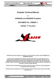
kWNmEngine Maintenance ManualJEM0002-1Jabiru Aircraft Pty LtdJabiru Model <strong>2200</strong> & 3300 Aircraft Engines3.18 Distributor Cylinder MapFigure 6 – Distributor Cylinder Map3.19 <strong>2200</strong> – Power Curve Multiply Kilowatts (kW) by 1.341 to get Horsepower (hp). i.e. 63.5 kW x 1.341 = 85 hp.POWER CURVE70.045065.060.055.050.045.040.035.030.025.0400350300250200150100POWERTORQUE20.0501500 1700 1900 2100 2300 2500 2700 2900 3100 3300RPMFigure 7 – Power / Torque Curve – Typical <strong>2200</strong>A EngineThis document is controlled while it remains on the Jabiru server. Once this no longer applies the document becomes uncontrolled.ISSUE 1 Dated : 26th July 2012 Issued By: DPS Page: 23 of 94C:\Aero_Craft_Australia\Jabiru\Jabiru_Documents_Edited\<strong>2200</strong>-3300_Engine_Maintenance_Manual\JEM0002_Issue1\JEM0002-1_Maint_22-33_unsigned.docx
kWkWNmNmEngine Maintenance ManualJEM0002-1Jabiru Aircraft Pty LtdJabiru Model <strong>2200</strong> & 3300 Aircraft Engines4 CYLINDER POWER CURVE65.045060.040055.035050.045.040.035.0300250200POWERTORQUE30.015025.010020.0501500 1700 1900 2100 2300 2500 2700 2900 3100 3300RPMFigure 8 – Power Curve - Typical <strong>2200</strong>C, <strong>2200</strong>B, Engine3.20 3300 – Power Curve6 CYLINDER POWER CURVE10045090400803507030060250POWERTORQUE50200401503010020501500 1700 1900 2100 2300 2500 2700 2900 3100 3300 3500RPMFigure 9 – Power / Torque Curves – Typical 3300 EngineThis document is controlled while it remains on the Jabiru server. Once this no longer applies the document becomes uncontrolled.ISSUE 1 Dated : 26th July 2012 Issued By: DPS Page: 24 of 94C:\Aero_Craft_Australia\Jabiru\Jabiru_Documents_Edited\<strong>2200</strong>-3300_Engine_Maintenance_Manual\JEM0002_Issue1\JEM0002-1_Maint_22-33_unsigned.docx
Engine Maintenance ManualJEM0002-1Jabiru Aircraft Pty LtdJabiru Model <strong>2200</strong> & 3300 Aircraft Engines4 OPERATING INSTRUCTIONSTo ensure that the engine operates reliably, carefully observe all of the operating &maintenance instructions.4.1 Daily ChecksNote: The checks given below are the basic requirements for safe operation of the engine.Any additional inspections required by the aircraft operating instructions (such as the PilotOperating Handbook) must also be carried out.Ensure free movement of throttle, choke & carburetor heat cables. Return throttle to idle beforeattempting to start engine.Check Oil Level, replenish if necessary.i) Check oil level by screwing in cap fully before withdrawingii) Oil level should be between the MAX & MIN marks - but must never be below thebottom of the dipstick.iii) Before long periods of operation, ensure that the level is at least at the mid position.iv) Difference in the oil quantity between MAX & MIN mark is 300 mL (0.317 US Quarts).Note: overfilling is detrimental to the engine; it will usually result in elevated enginetemperatures and rapid oil use.v) Also see Section 4.10 for special operating procedures for the first 25 hours ofoperation or after an overhaul.Check lubrication & fuel system for leaks.i) Visually inspect for signs of leakage on the ground where the aircraft was parkedovernightii) Inspect the oil cooler for leaks through the cowl openingiii) Visually inspect the underside of the aircraft for fresh oil or fuel residue.Check exhaust system for security.i) Wriggle the exhaust tail pipes by hand, checking for excessive movement, rubbing oncowls or unusual noises.With Ignition & Master OFF, and throttle closed, turn propeller by hand & observe engine forodd noises or heavy movements. Check for regular compression. If irregular, refer to TroubleShooting section of this Manual for corrective action.CAUTION:Prior to pulling through the propeller by hand, both ignition circuits & the Master Switchmust be switched OFF, the brakes applied and the throttle closed.A common cause of low compression is poorly sealing valves. Continued operation in thiscondition will result in damage to valves, valve seats, valve guides & overhead gear.4.2 Starting ProcedureWARNINGA hot engine may fire even with the ignition/s switched OFF.DO NOT TURN OVER A HOT <strong>ENGINE</strong> BY HAND Activate Starter for a maximum of 20 seconds, followed by a cooling period of 1 minute. When engine runs, adjust the throttle to achieve smooth running at approximately 1200 RPM.Deactivate Choke. Check Oil Pressure has risen within 5 seconds - if not, shut down.Note: After an oil change, crank the engine to obtain oil pressure before starting.This document is controlled while it remains on the Jabiru server. Once this no longer applies the document becomes uncontrolled.ISSUE 1 Dated : 26th July 2012 Issued By: DPS Page: 25 of 94C:\Aero_Craft_Australia\Jabiru\Jabiru_Documents_Edited\<strong>2200</strong>-3300_Engine_Maintenance_Manual\JEM0002_Issue1\JEM0002-1_Maint_22-33_unsigned.docx
Engine Maintenance ManualJEM0002-14.2.1 Cold EngineFuel TapChokeFuel PumpThrottleMasterIgnitionStarterJabiru Aircraft Pty LtdJabiru Model <strong>2200</strong> & 3300 Aircraft EnginesOPENON – HOLD (in cold conditions less than 20°C)ON for 10 seconds then offFULLY CLOSED: “cracked” throttle degrades chokeONBOTH ONPRESS4.2.2 Warm Engine As for cold start, with the following differences:ChokeOFFThrottle Slightly “Cracked” from off position (approx 2%).4.3 Warming Up Period Start the warming up period with the engine running at 1200 RPM for around 1 minute. Continue at 2000 RPM depending on ambient temperature, until oil temperature reaches 15°C(59°F). Check the two ignition circuits at 2000 RPMNote: Engine RPM should not drop by more than 100 RPM when 1 ignition is turned OFF.WARNINGDO NOT apply full power until CHT reaches 100 ° C (212 ° F)DO NOT apply full power until Oil Temperature reaches 50°C (104°F)DO NOT allow cylinder heads to rise above 180°C (356°F) during ground running.4.4 Ground RunningWhen running the engine on the ground before flight use minimum power settings andminimum time to avoid overheating: the engine is already run-in and further ground running canbe detrimental.Avoid prolonged ground running at elevated RPM as the engine can easily be over heatedduring ground operations – remember air ducts are designed for in flight cooling.Ground running at high power settings for more than a few minutes requires the use of special,oversize air ducts and oil cooler.WARNINGProlonged running at full power on the ground can cause engine overheating & damageunless special, oversized air ducts and oil coolers are used.4.5 Take-OffEnsure all temperatures and pressures are within limitations before applying take-off power.Climb with the engine at maximum continuous power.Observe Oil & Cylinder Head Temperatures & Oil Pressure.Max RPM at Full Throttle is 3300 RPMWARNINGLimits must not be exceeded!4.6 Engine StopIn normal conditions the engine will cool enough during descent & taxiing to permit it to bestopped by switching OFF the ignitions.This document is controlled while it remains on the Jabiru server. Once this no longer applies the document becomes uncontrolled.ISSUE 1 Dated : 26th July 2012 Issued By: DPS Page: 26 of 94C:\Aero_Craft_Australia\Jabiru\Jabiru_Documents_Edited\<strong>2200</strong>-3300_Engine_Maintenance_Manual\JEM0002_Issue1\JEM0002-1_Maint_22-33_unsigned.docx
Engine Maintenance ManualJEM0002-1Jabiru Aircraft Pty LtdJabiru Model <strong>2200</strong> & 3300 Aircraft Engines4.7 Engine Stop and Start During FlightReduce power to 2000 RPM to cool engine for 30 seconds, then to idle.Switch ignitions OFF. At higher speeds (above 90 KIAS) the propeller may windmill – reduceaircraft speed until propeller stops turning.Starting procedure is the same as ground starting: without choke for a warm engine & withchoke for a cold engine. As the engine cools quickly when stopped in flight the choke willnormally be needed to restart.WARNINGDO NOT apply the starter motor if the propeller is windmilling.4.8 Operation in WinterIt is recommended to carry out an engine service prior to the start of the cold season. Forselection of oil to suit colder weather consult the table of lubricants given in the EngineSpecifications above.Refer to Section 9.15 for the Troubleshooting Cold Start Checklist if the engine becomesdifficult to start.4.9 Carburettor IcingIt is important to distinguish between two kinds of icing:i) Icing due to water in fuel, andii) Icing due to high air humidity.4.9.1 Icing Due to Water in fuel Water in fuel will accumulate at the lower parts of the fuel system & can lead to freezing of fuellines, filters or jets. Remedies are:a) Drain, using fuel tank water drain.b) Ensure fuelling without traces of water. If in doubt, use a chamois as a filter.c) Install a generously sized water separator.d) Ensure that fuel lines do not permit the accumulation of water.e) Prevent condensation of humidity, i.e. avoid temperature differences between the aircraft &fuel.CAUTION:Do not add any form of alcohol (including automotive fuels with Ethanol or similaradditives) to a Jabiru Aircraft fiberglass fuel tank unless directed otherwise by the aircraftoperating manual. The sealant used in some (older) tanks will be damaged if it comes intocontact with alcohol, leading to leaks.4.9.2 Icing Due to High Air Humidity.Carburettor icing due to humidity may occur in the carburettor venturi & leads to performanceloss due to changes in the mixture.The only effective remedy is to preheat the intake air by use of the Carburettor Heat Control.4.10 New Engine OperationThis engine has been ground run to a specific run in program and is ready for flight whendelivered.Before initial start add oil to engine (2.3 litres with cooler for <strong>2200</strong> engine, 3.5L with cooler for3300 engine).The engine has been INHIBITED before dispatch from the factory. It is recommended that thisis removed before the first engine start: remove 1 spark plug from each cylinder and apply thestarter motor for around 10 seconds: inhibitor oil will be ejected from the cylinders. Re-fit sparkplugs & re-assemble engine.This document is controlled while it remains on the Jabiru server. Once this no longer applies the document becomes uncontrolled.ISSUE 1 Dated : 26th July 2012 Issued By: DPS Page: 27 of 94C:\Aero_Craft_Australia\Jabiru\Jabiru_Documents_Edited\<strong>2200</strong>-3300_Engine_Maintenance_Manual\JEM0002_Issue1\JEM0002-1_Maint_22-33_unsigned.docx
Engine Maintenance ManualJEM0002-1Jabiru Aircraft Pty LtdJabiru Model <strong>2200</strong> & 3300 Aircraft Engines Remove ALL plastic bungs on engine before starting. Bungs are fitted to the exhaust,carburettor, crankcase oil vent and fuel pump. The engine idle speed cannot be set accurately at the factory as the engine is run on aDynamometer only. Therefore it is necessary to adjust the throttle idle stop(s) to obtain theappropriate RPM (Section 3.10.1) when engine is warm before first flight. Note that as theengine run-in process progresses idle speed will gradually increase so initial idle should be setlow – within practical limitsWARNINGEnsure engine does not stall when throttle is set to idle. While cold, test by pulling BOTHthrottle levers against the idle stop. VARY your RPM when flying with a new engine. Do not “Baby” a new engine. The purpose of breaking in an engine correctly is to ensure a longreliable life. All moving parts need freeing up especially piston rings to cylinder walls. This isbest accomplished when the greatest B.M.E.P. (Break Mean Effective Pressure) occurs. Thatis at 75% power and above. Early running of an engine should include periods at high RPMand power settings. Failure to operate at realistic power settings could be detrimental to engine condition & longtermperformance. Always take off using full power – especially when the engine is new. Avoid heat build up – monitor CHT and oil temps. Note that Initial temps will be elevated due tothe friction of a new engine. Careful monitoring by the pilot is needed during this initial period toensure long life of the engine and its components. CIRCUIT WORK is a good sequence for initial run in work.i) Abbreviate circuits initiallyii) Step climbs, climb at shallow angles & higher airspeeds to reduce engine temperaturesiii) Do not carry out glide approachesiv) Gradually reduce powerv) Avoid sudden heating up and sudden cooling down Wherever practical, climb at a higher airspeed to assist engine cooling. For example, anaircraft with a best climb speed of 65 knots can often be climbed at around 80-85 knots withminimum impact on climb rate – although this varies depending on the airframe. At the higherspeed setting the engine has much more cooling air available and revs higher. Theseconditions provide the engine with a significantly improved environment and generally bothimprove performance and reduce temperatures. Note that all engine temperatures can be expected to drop noticeably when the new enginerun-in oil is replaced with standard oil.4.11 Engine InstallationAir cooled engines require careful design and tuning of the installation in order to operate attheir best.Ensure that installations are designed in consultation with the Jabiru Engine Installation Manualand that all installation targets (for cooling, EGT, RPM etc) are met.WARNINGImproper installation can cause severe engine damage and engine stoppage. It is theOperator’s responsibility to ensure that all installation targets are met. Damage to enginescaused by installation issues may not be covered by Jabiru’s Limited, Express Warranty.This document is controlled while it remains on the Jabiru server. Once this no longer applies the document becomes uncontrolled.ISSUE 1 Dated : 26th July 2012 Issued By: DPS Page: 28 of 94C:\Aero_Craft_Australia\Jabiru\Jabiru_Documents_Edited\<strong>2200</strong>-3300_Engine_Maintenance_Manual\JEM0002_Issue1\JEM0002-1_Maint_22-33_unsigned.docx
Engine Maintenance ManualJEM0002-1Jabiru Aircraft Pty LtdJabiru Model <strong>2200</strong> & 3300 Aircraft Engines5 Maintainer RequirementsThe following are recommended as the minimum requirements for someone carrying outmaintenance & inspection on Jabiru Engines.5.1 FacilitiesAn enclosed workspace with a sealed (i.e. not dirt) floor, adequate lighting, provision ofcompressed air & mains electricity.5.2 TrainingCompletion of an approved instruction course specific to Jabiru Engines. Approved coursesinclude those offered by Jabiru Aircraft Australia or by local Jabiru Aircraft representatives.5.3 RatingCommercial maintainers must hold suitable ratings as required by their local AirworthinessAuthority.5.4 ExperienceA minimum of 1 years experience working on Jabiru Engines under supervision isrecommended for commercial maintainers before working un-supervised.5.5 Tool & Gauge ControlTool and gauge control is an important part of aviation maintenance systems. Tools andgauges must be accurate enough for the intended use (i.e. a 12” steel ruler is not theappropriate tool to use to measure the cylinder bore diameter) and be accurately calibrated –for example by an approved laboratory.Calibrations must be kept up to date. This means a check calibration every year or morefrequently for regularly used, critical tooling.Even quality equipment will wear over time so items like reams, go / no-go gauges and valveseat cutting tools must periodically be checked to ensure they remain within limits.5.6 Tools:Access to the following tools will be required. All tools must be good quality items: Allen keys: 1/4”, 5/32” 3/16” and 3/16” ball end in regular 3/8” drive and “T” handle Circlip pliers (internal) Crowsfoot: 2” in regular 3/8” drive: 7/16” Hydraulic lifter tool (hydraulic lifter engines only) Pliers: long nose, regular square jaw, side cutters Ring/open end spanners: 5/16”, 3/8”, 7/16”, 1/2”, 9/16”, 10mm, 17mm Ratchet 3/8” drive, breaker bar, 2” extension bar, 3/8”, 7/16”, 1/2” sockets, 7/16” tube socket,18mm spark plug socket Screwdrivers: flat blade and Phillips head in various sizes Feeler gauges: metric and imperial sizes Torque wrench: 3/8” drive, “name” brand (Snap-On, Warren & Brown etc), recently calibratedThis document is controlled while it remains on the Jabiru server. Once this no longer applies the document becomes uncontrolled.ISSUE 1 Dated : 26th July 2012 Issued By: DPS Page: 29 of 94C:\Aero_Craft_Australia\Jabiru\Jabiru_Documents_Edited\<strong>2200</strong>-3300_Engine_Maintenance_Manual\JEM0002_Issue1\JEM0002-1_Maint_22-33_unsigned.docx
Engine Maintenance ManualJEM0002-1Jabiru Aircraft Pty LtdJabiru Model <strong>2200</strong> & 3300 Aircraft Engines5.7 Equipment:Access to the following equipment will be required: Bench vice with padded jaws Calipers: must read up to 180mm Degreasing/cleaning system with solvent/solution containment/recycling Dial indicator and magnetic stand, vee blocks Hand press Heat gun or small butane/propane torch with a soft pencil flame Micrometer and internal measuring tools, must read up to 100mm Multimeter or an ohmmeter Spring scale: must read up to 2.5kg in 0.1kg increments Thread taps: 1/4", 5/16”, 3/8” UNF and UNC Valve seat cutters: 30°, 45° and 60° Valve spring compressor, motorcycle type or a ‘G’ clamp with a machined spring cup5.8 General:Brass drifts, punches, rags, soft mallet, hammersGreases: molybdenum disulphide, general purposeLoctite compounds: 242/243/262 ThreadLocker, 515 Sealant, 620 Retainer, 7471 CureAcceleratorLubricants: engine oil, Nulon L90TorqueSeal brand security marking lacquer or similar, such as coloured nail varnishThis document is controlled while it remains on the Jabiru server. Once this no longer applies the document becomes uncontrolled.ISSUE 1 Dated : 26th July 2012 Issued By: DPS Page: 30 of 94C:\Aero_Craft_Australia\Jabiru\Jabiru_Documents_Edited\<strong>2200</strong>-3300_Engine_Maintenance_Manual\JEM0002_Issue1\JEM0002-1_Maint_22-33_unsigned.docx
Engine Maintenance ManualJEM0002-1Jabiru Aircraft Pty LtdJabiru Model <strong>2200</strong> & 3300 Aircraft Engines5.9 Sealants and CompoundsFigure 10 – Sealants, Compounds & Lubricants #1Greaseless Lubricant – used for cleaning, fitting rubber hoses, general purpose light lubricantwhich leaves no residue. Can be used for corrosion protection on steel parts in storage.Loctite 7471 Cure Accelerator - Loctite 7471 is used where increased cure speed of Loctiteanaerobic products is required. 7471 is particularly recommended when prevailingtemperature is low (
Engine Maintenance ManualJEM0002-1Jabiru Aircraft Pty LtdJabiru Model <strong>2200</strong> & 3300 Aircraft EnginesLoctite RTV Silicone 5920 is a premium silicone. Superior adhesion and oil resistance.Temperature range -75 °F to 700 °F intermittent; resists auto and shop fluids and vibrationLoctite Gasket Maker 515 Flange Sealant is a flexible, gasketing material for use on rigidmachined flanges with less than 0.015"gap.Loctite 577 is designed for the locking and sealing of metal threaded pipes and fittings. Usedto seal fuel, oil and brake fittings.Loctite Gasket Sealant #2 is a black, reliable, paste-like gasket sealant, dressing, and coating.Sets more slowly to a pliable film best suited for non-rigid, vibrating assemblies. Used on theinduction manifold.Bearing Blue – a high colour marking aid which spreads very easily, does not clog or dry out.Figure 12 – Sealants, Compounds & Lubricants #4Loctite Graphite-50 Anti-Seize is a thread lubricant. It is a non-metallic lubricant; but showsgood electrical conductivity in metal-to-metal joints. Use on machine threads, tapered pipethreads, for press-fit and slip-fit joints. This product is typically used in applications with anoperating range of -29 °C to +482 °C. Used on spark plugs and cylinder head screws.Loctite Nickel Anti-Seize is copper free. Recommended for stainless steel and other metalfittings. For preventing corrosion, seizing, and galling in harsh, chemical environments, andtemperatures to 2400 °F (1315 °C). Used on cylinder head screws.Figure 13 – Sealants, Compounds & Lubricants #4Loctite Gasket Maker 515 Flange Sealant is a flexible, gasketing material for use on rigidmachined flanges with less than 0.015"gap.Rubber grease – used to initially fill seals and lubricate rubber parts on assembly – thoughNulon L90 is preferred and generally more effective.High-temp grease – used to give initial start-up lubrication to many parts of the engine,including the oil seals.“Cam Honey” (Molybdenum Disulphide) for cam journals and lobes.This document is controlled while it remains on the Jabiru server. Once this no longer applies the document becomes uncontrolled.ISSUE 1 Dated : 26th July 2012 Issued By: DPS Page: 32 of 94C:\Aero_Craft_Australia\Jabiru\Jabiru_Documents_Edited\<strong>2200</strong>-3300_Engine_Maintenance_Manual\JEM0002_Issue1\JEM0002-1_Maint_22-33_unsigned.docx
Engine Maintenance ManualJEM0002-1Jabiru Aircraft Pty LtdJabiru Model <strong>2200</strong> & 3300 Aircraft Engines5.10 Loctite 620 & Other Retaining CompoundsFigure 14 – Sealants, Compounds & Lubricants #3Loctite 620 is designed for the bonding of cylindrical fitting parts. Typical applications includelocating pins in radiator assemblies, sleeves into pump housings and bearings in autotransmissions. Particularly suitable for applications where temperature resistance up to 200°Cis required. Used as a ultra-strong threadlock. Loctite 620 is specified in several places inJabiru Engine assembly where a reliable bond is essential. When using it, follow the rulesbelow:WARNINGFailure to use Loctite 620 correctly can result in engine failure- Check use-by dates. Loctite 620 (like most other compounds used on the engine forsealing etc) has a use-by date. Generally this is not printed on the bottle but can be foundby contacting the distributor and telling them the batch number.- Work fast. Loctite 620 can cure very quickly. All screws must be torqued to final settingsas quickly as practical. Anything more than a minute is not recommended, particularly ifcure accelerator spray (Loctite 7471) is used.- Only use as much as required/specified. Excess compound can make it nearlyimpossible to disassemble the parts later.- Surface preparation is critical. Threads must be cleaned and prepared properly.- To Remove. Can normally be achieved by heating the screw to over 150°C using a pencilpointgas burner. Minimise direct heat applied to the head of the screw as this can weakenthe drive socket – direct heat towards the thread as must as possible.Loctite 290 is designed for the locking and sealing of threaded fasteners. Because of its lowviscosity and capillary action, the product wicks between engaged threads and eliminates theneed to disassemble prior to application. The product cures when confined in the absence ofair between close fitting metal surfaces and prevents loosening and leakage from shock andvibration. The product can also fill porosity in welds, castings and powdered metal parts.Loctite 262 is designed for the permanent locking and sealing of threaded fasteners. Typicalapplications include the locking and sealing of large bolts and studs (up to M25 ). A mediumstrength threadlock.Loctite 243 is designed for the locking and sealing of threaded fasteners which require normaldisassembly with standard hand tools. Particularly suitable for applications on less activesubstrates such as stainless steel and plated surfaces, where disassembly with hand tools isrequired for servicing. A medium-strong threadlock. Typically used for cap screws into castingsor Aluminium.This document is controlled while it remains on the Jabiru server. Once this no longer applies the document becomes uncontrolled.ISSUE 1 Dated : 26th July 2012 Issued By: DPS Page: 33 of 94C:\Aero_Craft_Australia\Jabiru\Jabiru_Documents_Edited\<strong>2200</strong>-3300_Engine_Maintenance_Manual\JEM0002_Issue1\JEM0002-1_Maint_22-33_unsigned.docx
Engine Maintenance ManualJEM0002-1Jabiru Aircraft Pty LtdJabiru Model <strong>2200</strong> & 3300 Aircraft Engines5.11 Special ToolsSpecial tools can simplify maintenance and are shown in the photos below.Note that only those tools applicable to normal maintenance are shown below: refer to theJabiru Engine Overhaul Manual for additional tools required to carry out overhauls.Figure 15 – Valve Compressor / Lifter Bleed ToolsFigure 16 – Dimensional Details For Lifter ToolUsed to compress the valve springs, allowing the rocker shaft to be removed and the hydraulicvalve lifters to be bled.Figure 17 – Valve Leakage Vacuum TesterConnected to an air compressor generates a vacuum which is applied to the valve (whileclosed) to check for a poorly-sealing valve / seat.This document is controlled while it remains on the Jabiru server. Once this no longer applies the document becomes uncontrolled.ISSUE 1 Dated : 26th July 2012 Issued By: DPS Page: 34 of 94C:\Aero_Craft_Australia\Jabiru\Jabiru_Documents_Edited\<strong>2200</strong>-3300_Engine_Maintenance_Manual\JEM0002_Issue1\JEM0002-1_Maint_22-33_unsigned.docx
Engine Maintenance ManualJEM0002-1Jabiru Aircraft Pty LtdJabiru Model <strong>2200</strong> & 3300 Aircraft EnginesFigure 18 – Valve Spring Compressor / Collet RemoverModified sash clamp shown (commercial types are also available). Used to compress thevalve spring to allow the collets to be removed from the valve and then the valve to be removedfrom the head. Also used for installation.An adaptor is made by welding a compressor air fitting to thebase of an old spark plug. The adaptor is screwed into the sparkplug hole of a head and connected to the leak-down tester tocheck the condition of the cylinder assembly.Figure 19 – Leak Down TesterFigure 20 – Hand Press & InsertsA hand press is used to install rocker bushes, distributor shaft and crankshaft seals. Insertsare made for the press to suit the parts.An accurate optical tachometer. Reads directly from reflectivestrips fitted to the propeller and is used whenever an accuratecheck of RPM is required. Will usually read propeller RPM insunlight without reflective strips.Figure 21 – Optical TachometerThis document is controlled while it remains on the Jabiru server. Once this no longer applies the document becomes uncontrolled.ISSUE 1 Dated : 26th July 2012 Issued By: DPS Page: 35 of 94C:\Aero_Craft_Australia\Jabiru\Jabiru_Documents_Edited\<strong>2200</strong>-3300_Engine_Maintenance_Manual\JEM0002_Issue1\JEM0002-1_Maint_22-33_unsigned.docx
Engine Maintenance ManualJEM0002-1Jabiru Aircraft Pty LtdJabiru Model <strong>2200</strong> & 3300 Aircraft EnginesUsed during initial engine proof runs and / or running-in. Used as amore accurate gauge to confirm the readings of the standard aircraftoil pressure gauge. Fitting uses 1/8 NPT thread.Figure 22 – Supplementary Oil Pressure GaugeFigure 23 – “Finger Bar”A long lever arm fitted with pins that pit into the propeller flange holes. Allows the crank to beheld easily while tightening or loosening propeller flange or flywheel screws.The tap (at bottom) is used to cut a thread intothe needle seat (small part, middle-left). Theslide hammer (at top) screws into this threadand is used to draw the needle seat out of thecarburettor. The nylon driver (in centre) isused to fit the new needle seat to thecarburettor body.Figure 24 – Carburettor Needle Seat Remover and InstallerThis document is controlled while it remains on the Jabiru server. Once this no longer applies the document becomes uncontrolled.ISSUE 1 Dated : 26th July 2012 Issued By: DPS Page: 36 of 94C:\Aero_Craft_Australia\Jabiru\Jabiru_Documents_Edited\<strong>2200</strong>-3300_Engine_Maintenance_Manual\JEM0002_Issue1\JEM0002-1_Maint_22-33_unsigned.docx
Engine Maintenance ManualJEM0002-1Jabiru Aircraft Pty LtdJabiru Model <strong>2200</strong> & 3300 Aircraft EnginesCommercially available tool designed for hightorqueapplications on small nuts.Figure 25 – “Crowsfoot” AdaptorSnap-On tool FU14B – a universal joint with inbuilt 7/16”nut drive. Used for changing through-bolt nuts withoutremoving cylinder heads.Figure 26 – Universal Joint tool FU14BFigure 27 – Safety Wire / Wire PliersWire used to secure items (nuts, bolts etc) to prevent rotation in service.5.12 Torque / Tension WrenchL2L1Figure 28 – Torque Wrench & Crowsfoot Adaptor Setting 1This document is controlled while it remains on the Jabiru server. Once this no longer applies the document becomes uncontrolled.ISSUE 1 Dated : 26th July 2012 Issued By: DPS Page: 37 of 94C:\Aero_Craft_Australia\Jabiru\Jabiru_Documents_Edited\<strong>2200</strong>-3300_Engine_Maintenance_Manual\JEM0002_Issue1\JEM0002-1_Maint_22-33_unsigned.docx
Engine Maintenance ManualJEM0002-1Jabiru Aircraft Pty LtdJabiru Model <strong>2200</strong> & 3300 Aircraft EnginesL1L2 = 0Figure 29 – Torque Wrench & Crowsfoot Adaptor Setting 2A good torque wrench is an essential tool for maintaining and overhauling Jabiru Engines. It’simportant to realise however that even the best wrench needs calibrating occasionally. Thiscan be done using a dead weight on the end of a known arm or – preferably – sending thewrench away to be calibrated. Note that Civil Aviation Authorities generally require that the toolbe calibrated in a way which is traceable to a NATA-standard laboratory.A “Crowsfoot” extension as shown in Figure 25 is also necessary – it allows high torquesettings to be used on small nuts without damaging them. The crankcase through bolt nutsused on Jabiru engines are a good example of an application suitable for a crowsfootextension. However, when using the extension as shown in Figure 28 the extra length willthrow off the torque setting of the wrench. This must be corrected using the following formula:L1 is the distance from the middle of the grip of the handle to the centre of the wrench drive lugL2 is the distance in the direction of the handle from the centre of the wrench drive lug to thecentre of the nut socket of the adaptor.For example: a nut needs to be tensioned to 30lb.ft. The torque wrench is 12” long and thecrowsfoot extension is 2” long. The extension is oriented as shown in Figure 28. This meansthat the torque wrench must be set to:.If the extension is oriented at 90° to the wrench as shown in Figure 29 then no correction isneeded because L2 is zero.Corrected Torque Setting RequiredNo Correction Required.Figure 30 – Using A Crowsfoot AdaptorThis document is controlled while it remains on the Jabiru server. Once this no longer applies the document becomes uncontrolled.ISSUE 1 Dated : 26th July 2012 Issued By: DPS Page: 38 of 94C:\Aero_Craft_Australia\Jabiru\Jabiru_Documents_Edited\<strong>2200</strong>-3300_Engine_Maintenance_Manual\JEM0002_Issue1\JEM0002-1_Maint_22-33_unsigned.docx
Engine Maintenance ManualJEM0002-1Jabiru Aircraft Pty LtdJabiru Model <strong>2200</strong> & 3300 Aircraft Engines5.13 Torque Application ProcedureGood torque application technique is essential if an accurate bolt torque reading is going tobe obtained.Firstly the nut must be tightened smoothly. Any jerks or bumps can cause the torquereading to be obtained prematurely.The torque must be obtained while the nut is turning. If you stop to reposition the torquewrench and then the required torque reading is obtained without the nut turning, the nutneeds to be loosened a little and then tightened again so the torque reading is obtainedwhile turning.Unless specified otherwise all torque settings given in this manual are “dry” – i.e. no speciallubricant is applied to the threads or parts. Where directed otherwise it is vital that thedirections are followed exactly.This document is controlled while it remains on the Jabiru server. Once this no longer applies the document becomes uncontrolled.ISSUE 1 Dated : 26th July 2012 Issued By: DPS Page: 39 of 94C:\Aero_Craft_Australia\Jabiru\Jabiru_Documents_Edited\<strong>2200</strong>-3300_Engine_Maintenance_Manual\JEM0002_Issue1\JEM0002-1_Maint_22-33_unsigned.docx
Engine Maintenance ManualJEM0002-1Jabiru Aircraft Pty LtdJabiru Model <strong>2200</strong> & 3300 Aircraft Engines6 STORAGE & CLEANING6.1 Parking Whenever the engine is not active or being maintained it is strongly recommended that thefollowing points are covered to prevent contamination and pest ingress:- Engine air inlet- Exhaust outletIf the engine is not fitted in an airframe then the following must also be sealed:- Inlets to carburettor and fuel pump- Engine crankcase vent- Pipe fittings of oil cooler adaptor (if oil cooler is not currently connected).CAUTIONEquip all covers with tags or other high-visibility devices to minimise the chance ofinadvertent operation with covers still fitted.6.2 STORAGE The following procedures assume that the engine is installed in a Jabiru airframe. For otheraircraft types, refer to the manufacturer's service manual. If the engine is not fitted to anairframe, ignore those items referring to the airframe.Note: Failure to store the engine for a long period of time, in excess of 90 days, withouttaking the preventative measures as outlined in the manual will affect claims upon Jabiru’sLimited, Express Warranty.6.2.1 Flyable StorageFlyable storage is defined as a maximum of 30 days non-operational storage.Ensure that the engine has been stopped by turning off the fuel valve, thereby not leaving anyfuel in the carburettor bowl.Every 7th day the propeller should be rotated through 5 revolutions, without running the engine.Leave the propeller in the horizontal position to ensure even distribution of liquids in the wood.If left in the vertical position, liquids will drain to the lower tip resulting in an unbalancedpropeller.CAUTIONEnsure that the Master and Ignition Switches are OFF before turning motor!WARNINGDo not store MOGAS or fuels containing alcohol for longer than 30 days in a Jabiru aircraft.Refer to Service Letter JSL007 for details. Store under cover, away from direct sunlight. Ensure openings as detailed in Section 6.1 are covered.6.2.2 Returning Engine to Service From Flyable StorageAfter flyable storage, returning the engine to service is accomplished by performing a thoroughpre-flight inspection. Ensure all protective covers are removed.6.2.3 Temporary or Indefinite StorageTemporary storage is defined as engine in non-operational status for a maximum of 90 days.Treat as for flyable storage, plus:- For temporary storage, fill aircraft fuel tank with AVGAS (to prevent moisture accumulation).- For indefinite storage, drain fuel tank, ensure carburettor bowl is empty by running enginewith fuel valve off until it stops or by draining bowl.This document is controlled while it remains on the Jabiru server. Once this no longer applies the document becomes uncontrolled.ISSUE 1 Dated : 26th July 2012 Issued By: DPS Page: 40 of 94C:\Aero_Craft_Australia\Jabiru\Jabiru_Documents_Edited\<strong>2200</strong>-3300_Engine_Maintenance_Manual\JEM0002_Issue1\JEM0002-1_Maint_22-33_unsigned.docx
Engine Maintenance ManualJEM0002-1Jabiru Aircraft Pty LtdJabiru Model <strong>2200</strong> & 3300 Aircraft EnginesCAUTIONDo not store MOGAS or fuels containing alcohol for longer than 30 days in a Jabiru aircraft.Refer to Service Letter JSL007 for details.Then:1. Clean engine thoroughly.2. Seal or cover all openings.3. Remove battery and store in a cool dry place. Service the battery periodically and chargeas required.NOTE: It is recommended that batteries not being used should be charged every 30 days.4. Disconnect spark plug leads and remove spark plugs from each cylinder. Using an oil canor spray atomiser, spray preservative oil through a spark plug hole of each cylinder with thepiston in the down position. Rotate the propeller 10 – 12 times, leaving it in the horizontalposition. When all cylinders are treated leave prop horizontal and retreat each cylinder.NOTE: Use SHELL Aero fluid 2UN (MIL-C-6529C Type 1) or similar engine corrosioninhibitor.5. Install spark plugs and connect leads.6. Seal exhaust pipes. Attach a red streamer to each.7. The fuel tank breather must be covered but MUST NOT be sealed – the expansion ofgases within the tank can severely damage it if there is no escape path.8. Attach a warning placard to the instrument panel stating that vents and breathers havebeen sealed and that the engine must not be started with the seals in place.9. Every 7 days the propeller should be rotated through 5 revolutions without running theengine – leave propeller in the horizontal position.CAUTIONEnsure that the Master and Ignition Switches are OFF before turning motor!6.2.4 Inspection During Storage1. Generally inspect engine and clean as necessary.2. Inspect the interior of at least one cylinder through the spark plug hole for corrosion at leastonce a month.3. If, at the end of the 90 day period, the engine is to be continued in non-operational storage– repeat Steps above (most will only need to be checked).6.2.5 Returning Engine to Service After Temporary / Indefinite StorageAfter temporary storage, the procedures for returning the aircraft to service are as follows:1. Check battery and install.2. Check carburettor air filter and service if necessary.3. Remove warning placard from instrument panel.4. Remove materials used to cover openings.5. Remove, clean and gap spark plugs.6. While spark plugs are removed, rotate propeller using the starter motor for severalrevolutions to clear excess preservative oil from cylinders.CAUTIONEnsure that the Master and Ignition Switches are OFF before turning motor!7. Install spark plugs – torque to setting given in Table 10.8. Check fuel filter – replace if necessary.9. If returning to service after indefinite storage, fill fuel tanks with correct grade of fuel.10. Check fuel tank and fuel lines for moisture and sediment. Drain enough fuel to eliminateany moisture and sediment.11. Check that the fuel tank breathers are clear.12. Perform a thorough pre-flight inspection.13. Start and warm engine.This document is controlled while it remains on the Jabiru server. Once this no longer applies the document becomes uncontrolled.ISSUE 1 Dated : 26th July 2012 Issued By: DPS Page: 41 of 94C:\Aero_Craft_Australia\Jabiru\Jabiru_Documents_Edited\<strong>2200</strong>-3300_Engine_Maintenance_Manual\JEM0002_Issue1\JEM0002-1_Maint_22-33_unsigned.docx
Engine Maintenance ManualJEM0002-1Jabiru Aircraft Pty LtdJabiru Model <strong>2200</strong> & 3300 Aircraft Engines6.2.6 New Engine StorageIn many cases new or overhauled engines may be stored for some months or years beforebeing installed in an aircraft. All engines are treated with corrosion inhibitor by Jabiru AircraftAustralia before shipping from the factory however this treatment is roughly equivalent to thatdescribed in Section 6.2.3 above. It is intended for a maximum life of approximately 90 days –though the exact effective life of the treatment depends on the ambient temperature, humidityetc.If an engine is to be stored before use the owner must:i) Install the engine within 90 days (nominally) of the engine leaving the factory, orii) Repeat the Temporary Storage procedures given in Section 6.2.3 at a suitable interval(90 days nominally, depending on ambient temperature, humidity etc) and periodicallyinspect the engine in accordance with Section 6.2.4When the engine is to be run the storage measures must be reversed as detailed in theappropriate sections above.6.3 CLEANING <strong>ENGINE</strong> AND <strong>ENGINE</strong> COMPARTMENT The engine should be kept clean since dirty cooling fins and baffles can cause overheating ofthe engine. Also, cleaning is essential to minimise any danger of fire and provide easyinspection of components.CAUTIONDO NOT hose engine. Electrical components may be damaged by moisture. Ensureelectrical components are protected against moisture. Caustic cleaning solutions shouldnot be used. Recommended cleaning procedure is lightly spray with degreasing fluid – after sealing coilsand starter motor. WIPE clean with brush and cloth. Ensure the inside of the engine cowlings are also cleaned. Whenever possible, run engine after cleaning. This will warm it and encourage evaporation ofexcess moisture while the propeller wash will also blow away residual moisture. In some cases it may be necessary to also clean the firewall.This document is controlled while it remains on the Jabiru server. Once this no longer applies the document becomes uncontrolled.ISSUE 1 Dated : 26th July 2012 Issued By: DPS Page: 42 of 94C:\Aero_Craft_Australia\Jabiru\Jabiru_Documents_Edited\<strong>2200</strong>-3300_Engine_Maintenance_Manual\JEM0002_Issue1\JEM0002-1_Maint_22-33_unsigned.docx
Engine Maintenance ManualJEM0002-1Jabiru Aircraft Pty LtdJabiru Model <strong>2200</strong> & 3300 Aircraft Engines7 <strong>MAINTENANCE</strong>7.1 Service Interval ToleranceA tolerance of plus or minus 3 hours is allowable on all service intervals set within this manual7.2 Basic Inspection Procedure Test run engine: record anomalies. Remove the engine cowlings and inspect the engine bay in “dirty” condition. Clean the engine bay & propeller Carry out the inspections listed in Table 13. Test and re-assemble the aircraft. Test fly if required.7.3 Work SheetsWork sheets designed to suit the inspections below are included in Section 11. These sheetsare designed to be fast to fill out and to give all required detail from a particular inspectionwhen affixed in the log book.The use of these worksheets by maintainers is strongly recommended.7.4 Mandatory Inspections & Lifed Items. Engine life is as noted in Section 8.23. Lifed components of the engine are detailed in the Engine Overhaul Manual. Mandatory inspections are detailed in Table 13.7.4.1 Flexible Hoses All flexible hoses in the engine compartment should be replaced at engine overhaul or every 2years whichever comes first. Hoses which show visible deterioration (cracking, excessivehardening) should be replaced immediately, irrespective of age.7.5 Engine Inspection ChartThe chart below shows the recommended intervals at which items are to be inspected.Additional detail of the maintenance required for each point is given in the sections below theinspection chart.As shown in the chart, there are items to be inspected each 25 hours, 50 hours, 100 hours,each 200 hours and Annually. There are also special inspection items that require inspectionor servicing at intervals other than those in the normal inspection chart.When conducting an inspection at 50 hours, all items marked under Each 25 Hours areinspected, serviced or otherwise completed in addition to the items marked under Each 50Hours.When conducting an inspection at 100 hours, all items marked under Each 25 Hours & Each50 Hours are inspected, serviced or otherwise completed in addition to the items markedunder Each 100 Hours.At each 200 hours inspection the 25 Hour, 50 Hour & 100 hour items are completed inaddition to the items marked under Each 200 Hours.An inspection conducted Annually would likewise include the 25, 50, 100 and 200 hour items inaddition to the items marked under Annual Inspection.A complete aircraft inspection includes all 25, 50, 100, 200 hour and Annual items togetherwith those shown in the Aircraft Technical Manual and Propeller Manual.This document is controlled while it remains on the Jabiru server. Once this no longer applies the document becomes uncontrolled.ISSUE 1 Dated : 26th July 2012 Issued By: DPS Page: 43 of 94C:\Aero_Craft_Australia\Jabiru\Jabiru_Documents_Edited\<strong>2200</strong>-3300_Engine_Maintenance_Manual\JEM0002_Issue1\JEM0002-1_Maint_22-33_unsigned.docx
Engine Maintenance ManualJEM0002-1Jabiru Aircraft Pty LtdJabiru Model <strong>2200</strong> & 3300 Aircraft EnginesWARNINGBefore starting work on the engine it is recommended that the engine starter be disabled(via disconnecting the starter solenoid or similar) to reduce the risk of injury frominadvertent engine start.Table 13 – Engine Inspection ChartAnnual InspectionEach 200 HoursEach 100 HoursEach 50 HoursEach 25 HoursPROPELLER1. Spinner * * * *2. Spinner Mount Plates * * * *3. Spinner Screws * * * *4. Propeller * * * *5. Prop Tracking * * * *6. Propeller bolts/nuts – Tension * * * *7. Spinner Tracking * * * *<strong>ENGINE</strong> & <strong>ENGINE</strong> COMPARTMENTCheck for oil, fuel exhaust & induction leaks then cleanentire engine & compartment before inspection.1. Engine Pre-Inspection Test Run * * * *2. Engine Cowlings * * * *3. Inspection of Engine & Compartment – Pre Cleaning * * * * *4. Clean Engine & Compartment * * *5. Inspection of Engine Compartment - Clean * * *6. Check flywheel screw tensions * *7.Carburettor air filter –Check & replace if required* * * *This document is controlled while it remains on the Jabiru server. Once this no longer applies the document becomes uncontrolled.ISSUE 1 Dated : 26th July 2012 Issued By: DPS Page: 44 of 94C:\Aero_Craft_Australia\Jabiru\Jabiru_Documents_Edited\<strong>2200</strong>-3300_Engine_Maintenance_Manual\JEM0002_Issue1\JEM0002-1_Maint_22-33_unsigned.docx
Engine Maintenance ManualJEM0002-1Jabiru Aircraft Pty LtdJabiru Model <strong>2200</strong> & 3300 Aircraft EnginesAnnual InspectionEach 200 HoursEach 100 HoursEach 50 HoursEach 25 Hours8. Carburettor air filter – mandatory replacement * * *9. Engine baffles and air ducts * * * *10. Cylinders * * * *11. Crankcase & front crankcase seal * * * *12. Fuel hoses, lines and fittings * * * *13. Intake and exhaust systems * * * * *14. Ignition harness, distributor caps & rotors * * * *15. Check Spark Plug Gaps * * * *16. Replace Spark Plugs * * *17. Compression check or leak-down check * * * *18. Electrical wiring * * * * *19. Engine-Driven Fuel pump * * * * *20. Engine controls and linkages * * * *21. Engine mounts, mount structure * * * *22. Safety Wires * * * *23. Starter, solenoid and electrical connections * * * * *24. Coils and electrical connections * * * *25. Carburettor heat system * * * *26. Throttle and linkage * * * *27. Carburettor * * * *28. Oil system tubes and hoses * * * *29. Firewall * * * *30. Oil Collector Bottle on Firewall * * * * *This document is controlled while it remains on the Jabiru server. Once this no longer applies the document becomes uncontrolled.ISSUE 1 Dated : 26th July 2012 Issued By: DPS Page: 45 of 94C:\Aero_Craft_Australia\Jabiru\Jabiru_Documents_Edited\<strong>2200</strong>-3300_Engine_Maintenance_Manual\JEM0002_Issue1\JEM0002-1_Maint_22-33_unsigned.docx
Engine Maintenance ManualJEM0002-1Jabiru Aircraft Pty LtdJabiru Model <strong>2200</strong> & 3300 Aircraft EnginesAnnual InspectionEach 200 HoursEach 100 HoursEach 50 HoursEach 25 Hours31. Exhaust system – including muffler * * * *32. Cylinder Head bolt tension * * * *33. Valve Clearance Check (solid lifter engines only) * * * *34. Hydraulic Lifter & Rocker Inspection * * *35. Oil & filter change * * * * *36. SCAT hose condition * * * *37. Engine Post-Inspection Test Run * * * *Fuel System1 Replace fuel filter(s) * * *2 Drain valves, carburetor bowl * * * *3 Electronic fuel boost pump and fittings * * *4 Fuel lines, taps and connectors * * *5 Fire sleeves * * *6 Fuel Flow Rate *7.6 Pre-Maintenance Inspections:As all possible circumstances cannot be listed here, the following is provided as guidance only.A critical, trained eye is required and inspections should include, but not be limited to, thefollowing:Carry out a walk-around visual inspection of the aircraft, engine & propeller.When indicated in Table 13 carry out an engine test run as detailed in Section 8.1 to determineany abnormalities before maintenance.When indicated in Table 13 an engine run-up must be performed after completing maintenanceto determine that any discrepancies or abnormalities have been corrected. Test run to becarried out as detailed in Section 8.1WARNINGEngine runs on the ground must be short to avoid over-heating engine. Monitor enginetemperatures carefully during ground test runs.This document is controlled while it remains on the Jabiru server. Once this no longer applies the document becomes uncontrolled.ISSUE 1 Dated : 26th July 2012 Issued By: DPS Page: 46 of 94C:\Aero_Craft_Australia\Jabiru\Jabiru_Documents_Edited\<strong>2200</strong>-3300_Engine_Maintenance_Manual\JEM0002_Issue1\JEM0002-1_Maint_22-33_unsigned.docx
Engine Maintenance ManualJEM0002-1Jabiru Aircraft Pty LtdJabiru Model <strong>2200</strong> & 3300 Aircraft Engines7.7 Propeller – Inspection Details The items listed below provide additional details for the numbered inspection items in Table 13.These basic requirements must be carried out in conjunction with any other maintenancerequirements required by the propeller manufacturer. See Section 7.14 when operating with anon-approved propeller type. As all possible circumstances cannot be listed here, the following is provided as guidance only.A critical, trained eye is required and inspections should include, but not be limited to, thefollowing.1. Spinner: Remove & inspect for damage or wear.2. Spinner Mount Plates: Inspect for damage or wear. Ensure anchor nuts are secure and ingood condition.3. Spinner Screws: Inspect. Ensure all are in good condition.4. Propeller: Inspect for damage: nicks, cracks, fretting, corrosion, fibreglass de-lamination,stone or rain damage.5. Propeller Tracking: Check using the procedure given in Section 8.2.6. Propeller Bolts: Check to the torque setting given by the propeller manufacturer. For JabiruAircraft wooden propellers the torque settings are given in Table 10. This is to be donesimultaneously with the propeller tracking check.7. Spinner Tracking: Check using the procedure given in Section 8.2.7.8 Engine & Engine Compartment – Inspection Details The items listed below provide additional details for the numbered inspection items in Table 13. As all possible circumstances cannot be listed here, the following is provided as guidance only.A critical, trained eye is required and inspections should include, but not be limited to, thefollowing.1. Engine Pre-Inspection Test Run: As noted above, test run engine before maintenance tocheck for abnormalities. If oil pressure is outside limits it may be corrected by adjusting theoil pressure relief valve per Section 8.6.2. Engine Cowlings & Fasteners: Remove & check for damage or wear. Particularly inspectthe areas around the inlets and outlets for excess gaps between the cowl and the cooler /engine (generally any gap that two “average” fingers will fit through is consideredexcessive) or for indications that the cowl is rubbing on the engine, oil cooler or exhaust.Rubbing will produce excess vibrations and can damage parts (such as the oil cooler etc).Check that fasteners are fitting firmly and are not worn or damaged.3. Inspection of Engine & Compartment – Pre Cleaning. It is recommended that the enginecompartment be visually inspected twice: once while “dirty” – i.e. fresh from operation – andagain after cleaning. The “dirty” inspection allows the inspector to see patterns of leakageetc which are lost when the engine compartment is cleaned while the “clean” inspectionmay show items which were obscured by “dirt” previously. The engine and enginecompartment must be cleaned in accordance with Section 6.3 as a part of inspections &maintenance where noted in Table 13 above.4. Clean Engine & Compartment: In accordance with Section 6.35. Inspection of Engine Compartment – Clean: Check for damage or wear which may havebeen obscured by dirt etc during the “dirty” inspection. Thoroughly inspect the engine formissing or loose bolts, nuts, pins etc.6. Check flywheel screw tensions as detailed in Section 8.21: This inspection is to confirmthat the flywheel screws are intact and sufficiently tight. If any screws rotate the rectificationwork detailed in Section 8.21 must be carried out.7. Carburettor air filter: Check & replace if required.8. Carburettor air filter: Replace at the interval noted.9. Engine baffles and air ducts: Inspect for damage and wear. Particularly ensure that thescrews holding the ducts to the engine are secure – failure of this connection can result inducts being lifted from the engine by air pressure, pulling plug leads off spark plugs andresulting in engine stoppage. If necessary, fit baffle hard points as shown in Figure 31.This document is controlled while it remains on the Jabiru server. Once this no longer applies the document becomes uncontrolled.ISSUE 1 Dated : 26th July 2012 Issued By: DPS Page: 47 of 94C:\Aero_Craft_Australia\Jabiru\Jabiru_Documents_Edited\<strong>2200</strong>-3300_Engine_Maintenance_Manual\JEM0002_Issue1\JEM0002-1_Maint_22-33_unsigned.docx
Engine Maintenance ManualJEM0002-1Jabiru Aircraft Pty LtdJabiru Model <strong>2200</strong> & 3300 Aircraft EnginesCheck for correct fitting and signs of abrasion between engine and ducts or between ductsand cowlings.10. Cylinders: Inspect for excess oil leakage at the base, cracks, overheating (shown bydiscolouration) and other damage or wear.11. Crankcase & front crankcase seal: Check for leaks.Note: A leaking front crankcase seal can be an early indicator of unacceptable propellervibrations.12. Fuel hoses, lines and fittings: check for condition and replace any which are hard, crackedor softened.Note mandatory replacement requirements of Section 7.3.13. Intake and exhaust systems: Inspect for signs of damage or wear. In particular, inspect thesealant between the induction pipes and the induction manifold. Cracking here can result inair leakage, lean mixture and engine damage. Check for loose or missing bolts at theintake / exhaust flanges. Ensure that the carburettor heat muff is in good condition andfitted / connected correctly. Inspect all exhaust springs for condition & security.14. Ignition harness, distributor caps & rotors: Inspect for signs of damage or wear. Check forchafing where the leads have rubbed against projections in the engine bay. Check that allcaps are secure on the distributors and are fitting securely to the spark plugs. If any hightension caps are found to be a loose fit they can be adjusted as shown in Section 8.9.Inspect the condition of rotors & rotor buttons. Check for leakage from the distributor shaftseal.15. Spark plugs: Adjust the spark plug gap to within the limits set in Section 3.4. It isrecommended to set the gaps at the minimum limit during winter for easier starting.16. Spark plugs: Replace at the intervals specified in Table 13. Adjust the gap of the new plugsto within the limits set in Section 3.4. It is recommended to set the gaps at the minimumlimit during winter for easier starting.17. Compression check or leak-down check: Check in accordance with Section 8.17.18. Electrical wiring: Check wires for damage and wear, including chaffing, burning, dirty orloose connections. In particular, the connectors for the voltage regulator and the alternatormust be inspected for corrosion, loose connections or damage.19. Engine-Driven Fuel pump: Inspect for leakage, damage & security of connections.20. Engine controls and linkages: Inspect for damage and wear. Verify that all controls aremoving smoothly through their full range, that the stops are correctly adjusted and that theitem being controlled is moving through its correct arc – i.e. when the choke is fully ON orOFF in the cabin the choke arm on the carburettor moves to the fully ON or OFF positionrespectively.21. Engine mounts, mount structure: Inspect for damage, corrosion and wear including dents,scratches, rust, cracks etc. Inspect engine rubbers for cracking, bulging, softening or othersigns of deterioration.22. Safety Wires: Check safety wires are in place and correct.23. Starter, solenoid and electrical connections: Inspect connections. Ensure they are cleanand tight.24. Coils and electrical connections: Check the ignition coil gap is set correctly per Section 3.4& 8.2025. Carburettor heat system: Inspect for damage and wear. Verify that the control is movingsmoothly through its full range and that the carburettor heat flap is moving through itscorrect arc – i.e. when carby heat is selected as fully ON or OFF in the cabin, the flap in theair box moves to the fully ON or OFF position respectively.26. Throttle and linkage: Inspect for damage and wear. Verify that throttle is moving smoothlythrough its full range, that the stops are correctly adjusted and that the throttle arm on thecarburettor is moving through its correct arc – i.e. when the throttle is fully OPEN orCLOSED in the cabin the arm on the carburettor moves to the fully OPEN or CLOSEDposition respectively.Note: On the Bing carburettor best power is delivered when the throttle butterfly is notquite parallel with the carburettor throat (i.e. not quite fully open). The full power throttleThis document is controlled while it remains on the Jabiru server. Once this no longer applies the document becomes uncontrolled.ISSUE 1 Dated : 26th July 2012 Issued By: DPS Page: 48 of 94C:\Aero_Craft_Australia\Jabiru\Jabiru_Documents_Edited\<strong>2200</strong>-3300_Engine_Maintenance_Manual\JEM0002_Issue1\JEM0002-1_Maint_22-33_unsigned.docx
Engine Maintenance ManualJEM0002-1Jabiru Aircraft Pty LtdJabiru Model <strong>2200</strong> & 3300 Aircraft Enginesstop has accordingly been set at the factory for best power output and normally does notrequire adjustment in service.27. Carburettor: Inspect for damage or wear. Remove the bowl and check for contamination.Inspect the carburettor mount / coupling to check for cracking or degradation.28. Oil system tubes and hoses: check for condition and replace any which are hard, crackedor softened.Note mandatory replacement requirements of Section 7.3.29. Firewall: Inspect for damage & cleanliness. Particularly check that the electricalconnections to the firewall (master earth tag, starter solenoid etc) are clean.30. Oil Collector Bottle on Firewall: Measure volume of oil inside then empty. Excess oil in thebottle can indicate several engine issues – see troubleshooting section for details.31. Exhaust system – including muffler: Inspect for damage or wear. Check for appropriatetension on exhaust flange screws.32. Cylinder Head bolt tension: Check as noted in Section 8.15.33. Valve clearance check (solid lifter engines only): Check as noted in Section 8.16.34. Hydraulic Lifter & Rocker Inspection: Check as noted in Section 8.1935. Oil & filter change: Carry out as detailed in Section 8.536. SCAT hose condition: Check for damage or wear. Ensure that where the hose connects tothe carburettor there is minimum bunching – a rough surface here from bunched hose canadversely affect the function of the carburettor.37. Engine Post-Inspection Test Run as detailed in Section 8.1.7.9 Fuel System – Inspection Details1. Fuel filter(s): Change filter at the interval noted in Table 13.2. Fuel drain valves, carburettor bowl: Inspect for wear or damage.3. Electronic fuel boost pump and fittings: Inspect for wear or damage.4. Fuel lines, taps and connectors: Check flexible lines for condition and replace any whichare hard, cracked or softened. Inspect for fittings for wear or damage. Verify correctfunction of tap(s) and that correct fuel tap placards are fitted.Note mandatory replacement requirements of Section 7.3.5. Fire sleeves: Check for wear and correct fitment per Figure 35.6. Fuel flow rate: Check as detailed in Section 8.187.10 Special Maintenance - Check after initial 5 Hours – Solid Lifter OnlyFor a new aircraft or one equipped with a new or overhauled engine the first few hours ofoperation are critical. During this time the engine must be monitored carefully in operation andduring scheduled maintenance.The following list requirements for mandatory maintenance and inspection recommendationsfor engines in their first 5 hours in service or since overhaul / major engine maintenance.As all possible circumstances cannot be listed here, the following is provided as guidance only.A critical, trained eye is required and inspections should include, but not be limited to, thefollowing:1. Remove engine cowlings2. Check engine mounts.3. Thoroughly check engine for missing or loose bolts, nuts, pins, etc.4. Check fit of cooling air ducts & baffles. Check the engine (including oil cooler) for signs ofabrasion against cowls and ducts.5. Check induction and exhaust flange for loose bolts.6. Check safety wires, ignition wiring & hose connections.7. Re-torque cylinder head bolts to the setting noted in Table 10 in a diagonal pattern (seeSection 8.15).8. Check & adjust valve clearances.9. Check exhaust system, check exhaust cap screw tensions.10. Check fuel system for leaks & abrasion.This document is controlled while it remains on the Jabiru server. Once this no longer applies the document becomes uncontrolled.ISSUE 1 Dated : 26th July 2012 Issued By: DPS Page: 49 of 94C:\Aero_Craft_Australia\Jabiru\Jabiru_Documents_Edited\<strong>2200</strong>-3300_Engine_Maintenance_Manual\JEM0002_Issue1\JEM0002-1_Maint_22-33_unsigned.docx
Engine Maintenance ManualJEM0002-1Jabiru Aircraft Pty LtdJabiru Model <strong>2200</strong> & 3300 Aircraft Engines11. Check wiring for damage & for tightness.12. Test run engine per Section 8.1.7.11 Special Maintenance - Check after initial 10 HoursFor a new aircraft or one equipped with a new or overhauled engine the first few hours ofoperation are critical. During this time the engine must be monitored carefully in operation andduring scheduled maintenance.The following list requirements for mandatory maintenance and inspection recommendationsfor engines in their first 10 hours in service or since overhaul / major engine maintenance.As all possible circumstances cannot be listed here, the following is provided as guidance only.A critical, trained eye is required and inspections should include, but not be limited to, thefollowing:13. Remove engine cowlings14. Check engine mounts.15. Thoroughly check engine for missing or loose bolts, nuts, pins, etc.16. Check fit of cooling air ducts & baffles. Check the engine (including oil cooler) for signs ofabrasion against cowls and ducts.17. Check induction and exhaust flange for loose bolts.18. Check safety wires, ignition wiring & hose connections.19. Re-torque cylinder head bolts to the setting noted in Table 10 in a diagonal pattern (seeSection 8.15).20. Check valve clearances (Solid lifter engines only).21. Check exhaust system, check exhaust cap screw tensions.22. Check fuel system for leaks & abrasion.23. Check wiring for damage & for tightness.24. Test run engine per Section 8.1.7.12 Special Inspection - Check after initial 25 HoursThe following list requirements for mandatory maintenance and inspection recommendationsfor engines in their first 25 hours in service or since overhaul / major engine maintenance.As all possible circumstances cannot be listed here, the following is provided as guidance only.A critical, trained eye is required and inspections should include, but not be limited to, thefollowing:1. Conduct the items shown under “Check after initial 10 Hours”.2. Oil Change. Refer to Section 8.5 for details. Use normal aviation running oil.3. Change oil filter. Inspect old filter for excessive contamination, metal filings etc.7.13 Special Inspection - Check After Initial 50 HoursFor a new aircraft the first few hours of operation are critical. During this time the engine mustbe monitored carefully in operation and during scheduled maintenance.The following list requirements for mandatory maintenance and inspection recommendationsfor Jabiru Engines fitted to new aircraft after their first 50 hours in service.As all possible circumstances cannot be listed here, the following is provided as guidance only.A critical, trained eye is required and inspections should include, but not be limited to, thefollowing:1. Conduct the items shown in Table 13 for a standard 50 hour inspection.2. Replace fuel filter.This document is controlled while it remains on the Jabiru server. Once this no longer applies the document becomes uncontrolled.ISSUE 1 Dated : 26th July 2012 Issued By: DPS Page: 50 of 94C:\Aero_Craft_Australia\Jabiru\Jabiru_Documents_Edited\<strong>2200</strong>-3300_Engine_Maintenance_Manual\JEM0002_Issue1\JEM0002-1_Maint_22-33_unsigned.docx
Engine Maintenance ManualJEM0002-1Jabiru Aircraft Pty LtdJabiru Model <strong>2200</strong> & 3300 Aircraft Engines7.14 Special Maintenance – Non-Approved Propellers As noted, operators who choose to fit a non-approved propeller to their Jabiru engine do so attheir own risk and a system of additional maintenance is recommended to monitor the enginefor possible detrimental effects. This section has been added to the manual to help guide such maintenance. However, asJabiru cannot anticipate every combination of engine, airframe and propeller this is strictly of aninformational basis. It is not a complete or inclusive maintenance schedule, rather an overallguide directing which areas are likely to need additional attention.WARNINGUsing a non-approved propeller may lead to unforeseen operational, airworthiness, safety,financial or legal problems. Jabiru Aircraft accept no responsibility for such issues.The following are recommended IN ADDITION to the normal engine maintenance program.Where the maintenance requirements listed below differ from those of a third-party propellersupplier the lesser time interval should be used. i.e. if the table below calls for the propeller tobe re-balanced annually but the propeller manufacturer recommends balancing every 100hours or 6 months then the propeller manufacturer’s recommendations should be used.Visual inspections of the propeller and propeller flange installation should check for excessmetal oxide (appears as rust) or black chaffing dust originating from the flange. This is often anearly indication of movement between the parts and potential failure. Oil leaks etc in this areaand around the flywheel must be addressed quickly as they can both cause and mask otherproblems.Oil leaks from the front crankshaft seal have also been found to be an indicator ofunacceptable propeller vibrations in some cases.Table 14 – Special Maintenance Recommendations – Non-Approved Propellers1.Annual InspectionEach 500 HoursEach 100 HoursEach 50 HoursSpinner, spinner flange & hardware –Check condition.* * *2. Propeller general condition – visual/hand check * * * *3. Propeller blade pitch, tracking * * *4.Propeller mounting hardware(bolts, nuts, bushes etc) tension & condition check* * *5. Propeller balance * *6.7.8.Propeller flange installation – visual inspection(no disassembly required)Propeller flange screws – REPLACERefer to engine overhaul manual for guidancePropeller flange run-out check(per prop strike inspection detailed below)* * * ***This document is controlled while it remains on the Jabiru server. Once this no longer applies the document becomes uncontrolled.ISSUE 1 Dated : 26th July 2012 Issued By: DPS Page: 51 of 94C:\Aero_Craft_Australia\Jabiru\Jabiru_Documents_Edited\<strong>2200</strong>-3300_Engine_Maintenance_Manual\JEM0002_Issue1\JEM0002-1_Maint_22-33_unsigned.docx
Engine Maintenance ManualJEM0002-1Jabiru Aircraft Pty LtdJabiru Model <strong>2200</strong> & 3300 Aircraft Engines9.10.Annual InspectionEach 500 HoursEach 100 HoursEach 50 HoursCrank run-out check(per prop strike inspection detailed below)Flywheel Screws – REPLACERefer to engine overhaul manual for guidance**This document is controlled while it remains on the Jabiru server. Once this no longer applies the document becomes uncontrolled.ISSUE 1 Dated : 26th July 2012 Issued By: DPS Page: 52 of 94C:\Aero_Craft_Australia\Jabiru\Jabiru_Documents_Edited\<strong>2200</strong>-3300_Engine_Maintenance_Manual\JEM0002_Issue1\JEM0002-1_Maint_22-33_unsigned.docx
Engine Maintenance ManualJEM0002-1Jabiru Aircraft Pty LtdJabiru Model <strong>2200</strong> & 3300 Aircraft Engines8 Service & Repair ProceduresThis section details the procedures to be used to carry out the regular maintenance operationsdetailed in Section 7Heavy maintenance procedures (such as piston replacement etc) are detailed in the JabiruEngine Overhaul Manual.8.1 Engine Test RunBefore beginning the step-by-step inspection, start, run-up and shut-down the engine inaccordance with instructions in the Flight Manual.Before starting, ensure the aircraft is suitably positioned. Aircraft must be:- Oriented into wind- Positioned where there is no long grass, loose gravel, sticks or dirt under the propeller.- Positioned where the wash from the propeller will not blow into hangars, at aircraft orpersonnel etc.- Positioned where there is sufficient space to regain control of the aircraft in the event ofbrake failure.- Positioned with consideration to other personnel – i.e. where noise impacts are minimised.During the run-up, observe the following, making note of any discrepancies or abnormalities:- Engine temperatures and pressures.- Static RPM within limits of Section 3.5.- Magneto drop within limits of Section 3.13.- Engine response to changes in power.- Any unusual engine noises.- Fuel shut-off valve; operate engine in ON position and in OFF position long enough toensure shut-off functions properly.- Idling speed within limits of Section 3.10.1.After the inspection has been completed, an engine run-up should again be performed todetermine that any discrepancies or abnormalities have been corrected.WARNINGEngine runs on the ground must be short to avoid over-heating engine. Monitor enginetemperatures carefully during ground test runs.Test runs are to be carried out by appropriately trained, authorised personnel only8.2 Propeller TrackingLocate a fixed object on a flat floor so that it just clears the propeller tips when rotating thePropeller by hand.Check that each blade clears the object by the same amount.If the Propeller is outside the approved tolerance, refer to <strong>JABIRU</strong> Aircraft Pty Ltd or our localapproved representative.Blade tracking tolerance will normally be supplied by the propeller manufacturer. For Jabiruwooden propellers the Tracking Error Tolerance is +/- 2mm.WARNINGDO NOT exceed maximum propeller mount bolt torque limits provided by propellermanufacturer.Ensure ignitions are turned OFF before turning crank by hand.Propeller tips are fragile: take care that they do not hit the tacking indicator or other objectsduring testing.This document is controlled while it remains on the Jabiru server. Once this no longer applies the document becomes uncontrolled.ISSUE 1 Dated : 26th July 2012 Issued By: DPS Page: 53 of 94C:\Aero_Craft_Australia\Jabiru\Jabiru_Documents_Edited\<strong>2200</strong>-3300_Engine_Maintenance_Manual\JEM0002_Issue1\JEM0002-1_Maint_22-33_unsigned.docx
Engine Maintenance ManualJEM0002-1Jabiru Aircraft Pty LtdJabiru Model <strong>2200</strong> & 3300 Aircraft Engines8.3 Spinner InspectionsChecking spinner tracking is part of normal maintenance.Locate a fixed object on a flat floor to just clear the lower edge of the tip of the Spinner.Rotate the propeller by hand and check that the Spinner runs true.Spinner tracking can be adjusted by loosening the mounting screws, moving the tip in therequired direction and re-tightening.If required, spinner balance can be checked by removing the spinner and balancing it on asharp probe positioned inside the centre of the spinner tip. Balance can be adjusted by addingweight as required. Contact Jabiru Aircraft or our local approved representative for details.Note: spinner balancing is not a part of normal maintenance. It is provided for referencepurposes & for troubleshooting vibration.8.4 Ram Air Duct InspectionsInspect ducts for damage or wear.If the hard-points where the ducts screw to the engine are damaged they must be repaired bythe installation of reinforcement as shown in Figure 31:While the duct is sitting on the engine position the reinforcement as shown and mark the tworivet holes.Drill duct to suit and rivet the reinforcement in place.Figure 31 – Air Duct Hard Point ReinforcementThis document is controlled while it remains on the Jabiru server. Once this no longer applies the document becomes uncontrolled.ISSUE 1 Dated : 26th July 2012 Issued By: DPS Page: 54 of 94C:\Aero_Craft_Australia\Jabiru\Jabiru_Documents_Edited\<strong>2200</strong>-3300_Engine_Maintenance_Manual\JEM0002_Issue1\JEM0002-1_Maint_22-33_unsigned.docx
Engine Maintenance ManualJEM0002-1Jabiru Aircraft Pty LtdJabiru Model <strong>2200</strong> & 3300 Aircraft Engines8.5 Oil & Filter Change Oil & filter change at the interval noted in Table 13. Before starting, carry out a visual check for leaks. Cut the safety wire on sump plug, remove it & drain the oil while engine is still warm (not hot!). Remove the old oil filter while the sump is draining. Ensure the oil seal of the old filter comesaway from the engine with the filter. Inspect the sump plug seal & replace if worn or damaged. Re-fit the sump plug. Tighten to the tension given in Table 10 & lock wire per Section 8.20 Take a new oil filter and fill with new oil. Lubricate the seal on the base of the filter with newengine oil and fit the filter to the engine. Tighten until seal touches the engine and then turn itan additional ¾ - 1 full turn. DO NOT apply excess torque to the filter – it should be possible toinstall the filter by hand. If tools are used to tighten the filter take care not to damage it – thefilter walls are very thin and slight damage such as dents or scratches can result in subsequentfilter failure.CAUTIONJabiru Aircraft recommend that the oil filter is not safety wired. Experience has shown thatthe filter will not move if installed correctly and that using safety wire, hose clamps etc canpotentially damage the filter and lead to failure. Fill with oil. (approx 2.3 litres for <strong>2200</strong> engine, 3.5 litres for 3300 engine) Check oil level then run the engine. The MAX mark must not be exceeded after the engine hasbeen run to ensure that all lines, filters etc are full. Use only registered brand oils meeting the specification detailed in Section 3.8. DO NOT drain the oil cooler during a normal oil change. The cooler holds only a small amountof old oil which has negligible effect on the new oil. Taking the hoses on & off the cooler canprematurely age the oil lines and lead to hoses slipping off the cooler. Clean any oil residue from the oil / filter change before returning to service.8.6 Oil Pressure Relief Valve AdjustmentRemove the oil filter.Remove the oil cooler adaptor. Note that to gain sufficient slack in the oil lines it may benecessary to remove the oil cooler from its mounting.Remove the circlip and draw the valve assembly out of the case.Inspect the sealing face of the relief valve plunger. If there are visible nicks or damage – or ifthe plunger is made from brass – then it must be replaced. If a new plunger is to be installed itmust be lapped to the front restraining washer as noted in the Jabiru Engine Overhaul Manual.If the pressure of the engine needs to be increased another washer can be added behind thespring (item 2 in Figure 32 below). If the pressure needs to be reduced then a washer can beremoved.Re-assemble the valve.Ensure that the spring is not coil-bound: press on the tip of the oil valve plunger and ensurethere is a minimum of 1mm movement.This document is controlled while it remains on the Jabiru server. Once this no longer applies the document becomes uncontrolled.ISSUE 1 Dated : 26th July 2012 Issued By: DPS Page: 55 of 94C:\Aero_Craft_Australia\Jabiru\Jabiru_Documents_Edited\<strong>2200</strong>-3300_Engine_Maintenance_Manual\JEM0002_Issue1\JEM0002-1_Maint_22-33_unsigned.docx
Engine Maintenance ManualJEM0002-1Jabiru Aircraft Pty LtdJabiru Model <strong>2200</strong> & 3300 Aircraft Engines8.7 Air Intake FilterFigure 32 – Oil Pressure Relief Valve AssemblyRemove the front of the air filter housing & extract filter.Clean filter by removing from the intake housing & blowing compressed air against the directionof the intake flow.For operation in heavy dust conditions, clean air filter at shorter intervals than recommendedfor normal conditions.A clogged or wet filter will reduce engine performance as well as promote premature enginewear.This document is controlled while it remains on the Jabiru server. Once this no longer applies the document becomes uncontrolled.ISSUE 1 Dated : 26th July 2012 Issued By: DPS Page: 56 of 94C:\Aero_Craft_Australia\Jabiru\Jabiru_Documents_Edited\<strong>2200</strong>-3300_Engine_Maintenance_Manual\JEM0002_Issue1\JEM0002-1_Maint_22-33_unsigned.docx
Engine Maintenance ManualJEM0002-1Jabiru Aircraft Pty LtdJabiru Model <strong>2200</strong> & 3300 Aircraft Engines8.8 Ignition Coil Gap Adjustment For best performance the gap between the ignition coil and the flywheel magnets must be setto the specification given in Section 3.4. To set gap, use a piece of gauge material the correct thickness. A metal gauge can be used,as can alternatives made from plastic etc. Loosen the screws holding the coil in place, move it away from the flywheel and then retighten.This is to increase the size of the gap and allow the gauge to be inserted. Rotate the crank until a magnet pole plate aligns with the coil being adjusted. Place the gauge material between the coil and the flywheel magnet. Loosen the screwsholding the coil and allow the magnets to suck it against the gauge. Tighten the screws, locking the coil in place. Rotate the crank to draw the gauge material from between the coil and the flywheel. When both coils are adjusted check that the gap is the same for both coils and all magnet poleplates.CAUTIONWhen working at the rear of the engine care must be taken to ensure no metallic materialsare captured by the ignition or alternator magnets.8.9 High Tension Lead Inspection & MaintenanceFigure 6 above shows the High-Tension lead connections between the distributors and thespark plugs.At the intervals noted in Table 13 high tension leads must be inspected and, if necessary,adjusted.Inspect the length of each lead, checking for cracked or damaged insulation. Particularly checkareas where the lead may have been rubbing against other items in the engine bay.Check the fit of the high-tension lead caps onto the distributor and spark plugs. Under the heatand vibration of operation the lead caps may gradually work their way off the distributor –particularly if lubricant has been applied to the caps. If lubricant is found, clean it off using acleaner which does not leave a residue (Ether-based starting sprays can often be used).Visually check the metal contacts inside the caps. If the fit is loose or if the contact is visiblydamaged as shown in Figure 33 then a screwdriver or similar must be used to re-shape thecontact (it should be round) and to re-size it for a better fit – for a spark plug the diameter of thecontact needs to be reduced to tighten while for a distributor cap it needs to be expanded.Each cap should fit with a clear “click” as it connects to the distributor cap or spark plug. Takecare not to over-bend and contact and replace any which are damaged.Figure 33 – Adjusting High Tension Lead CapsThis document is controlled while it remains on the Jabiru server. Once this no longer applies the document becomes uncontrolled.ISSUE 1 Dated : 26th July 2012 Issued By: DPS Page: 57 of 94C:\Aero_Craft_Australia\Jabiru\Jabiru_Documents_Edited\<strong>2200</strong>-3300_Engine_Maintenance_Manual\JEM0002_Issue1\JEM0002-1_Maint_22-33_unsigned.docx
Engine Maintenance ManualJEM0002-1Jabiru Aircraft Pty LtdJabiru Model <strong>2200</strong> & 3300 Aircraft Engines8.10 Spark Plugs Do not use steel or brass brushes for cleaning & never sandblast plugs. Clean with plastic brush in a solvent. Check electrode gap & if necessary, adjust to the gap given in Section 3.4 by carefully bendingthe electrode.CAUTIONDO NOT reduce the electrode gap by tapping the plug against a hard object – damage to theinsulator can result. Recommended Plugs: NGK D9EA. Note that spark plug terminal nuts must be used (Figure34) Use suitable anti-seize on thread and install to the torque setting given in Table 10. Note thatengine must be cold to accurately set plug tension. When using CHT sensors equipped with a ring terminal under the spark plug ensure the ringterminals are centred over the plug.CAUTIONOff-centre terminals will give a false, high CHT reading.Spark plug terminal nutFigure 34 – Spark Plug Terminal Nut8.11 Carburettor Inspection & AdjustmentCheck carburettor joints for degradation.Check carburettor linkage for full & free movement, correct positioning of stops and security.Ensure that when the choke is selected fully ON and released the arm on the carburettor doesnot move – if the choke arm springs back slightly when the control in the cabin is released thiscan result in difficulty starting the engine. When in the ON position the choke lever on thecarburettor must remain in the fully ON position regardless of if there is a hand on the control inthe cabin.The carburettor automatically adjusts the mixture to account for altitude – there is no provisionfor in-flight mixture adjustment as standard.Ensure that the carburettor sense tube is connected from the carburettor to a fitting on thefiltered side of the hot air mixer box.Idle stop screw is a 7mm screw against throttle lever. Adjust its position to adjust engine idlespeed. Note that the throttle idle stops inside the cabin may also need to be adjusted.Standard idle mixture screw position is 1-1/4 turns out. Fine adjustment may be necessary togive a smooth idle.Remove the spring clip and detach the bowl from the carburettor. Measure the distance fromthe fuel surface to the top of the bowl – it should be approximately 12mm.Inspect the bowl for dirt or contamination and clean if required. Inspect the visible jets of thecarburettor and clean if required.This document is controlled while it remains on the Jabiru server. Once this no longer applies the document becomes uncontrolled.ISSUE 1 Dated : 26th July 2012 Issued By: DPS Page: 58 of 94C:\Aero_Craft_Australia\Jabiru\Jabiru_Documents_Edited\<strong>2200</strong>-3300_Engine_Maintenance_Manual\JEM0002_Issue1\JEM0002-1_Maint_22-33_unsigned.docx
Engine Maintenance ManualJEM0002-1Jabiru Aircraft Pty LtdJabiru Model <strong>2200</strong> & 3300 Aircraft EnginesGently lift the floats of the carburettor with the bowl removed until the float needle touches itsseat. The floats should be approximately level when the needle touches the seat. If necessarythe float assembly can be removed by pressing out the pivot pin and the float height adjustedby gently bending the arm which connects to the float needle.Inspect the condition of the seal between carburettor and bowl.Re-fit the bowl and snap the clip back in place.8.11.1 TuningCAUTIONEnsure clip is properly on: pressed up against the stopper cast into the bowl.The mixture is set by selecting jet sizes. As supplied, the engine has jets to suit a majority ofinstallations. However, the mixture may be affected by many variables and in some casesadjustment will be necessary.It is strongly recommended that for any new installation a thorough assessment of the engine’sfuel/air mixture is carried out. This may be done by EGT sensors or Lambda type sensors.Details are given in the engine installation manual and Jabiru Service Bulletin JSB018.CAUTIONDo not change carburettor settings without consulting with Jabiru Aircraft or our localauthorised representative. If EGT readings fall outside the range given above, contactJabiru Aircraft or our local authorised representative.Spark plug colour can be used as a general indicator of the health of the engine and thesuitability of the fuel/air mixture:a. Brown to Dark Brown :- Plug & calibration is correct.b. Velvet Black:- Mixture too rich. Check choke. Insufficient air intake. Check for clogged airfilter.c. Oily, Glossy Coating:- Misfiring. Too much oil in combustion chamber. Worn cylinder pistonrings.d. Whitish with Melt Droplets:- Mixture too lean. Leaking valves.CAUTIONThis guide is only relevant when running the engine on AVGAS. Unleaded fuels givedifferent plug colours which are generally unsuitable for use in evaluating engine tuning.The plug colour reflects the most recent running of the engine – if the engine has run at idlefor some time the plug colour will reflect the mixture at idle.WARNINGSpark plug colour is a very general guide only. Tuning adjustments must ONLY be made onthe basis of EGT or Lambda sensor results.DO NOT ADJUST <strong>ENGINE</strong> TUNING BASED ON SPARK PLUG COLOURS ALONEThis document is controlled while it remains on the Jabiru server. Once this no longer applies the document becomes uncontrolled.ISSUE 1 Dated : 26th July 2012 Issued By: DPS Page: 59 of 94C:\Aero_Craft_Australia\Jabiru\Jabiru_Documents_Edited\<strong>2200</strong>-3300_Engine_Maintenance_Manual\JEM0002_Issue1\JEM0002-1_Maint_22-33_unsigned.docx
Engine Maintenance ManualJEM0002-1Jabiru Aircraft Pty LtdJabiru Model <strong>2200</strong> & 3300 Aircraft Engines8.12 Distributor & Rotor Inspection & AdjustmentRemove the clamps and rotors from the engine. Inspect the distributor caps, rotor button androtor for damage or wear.The rotor is glued to the distributor shaft. If it or the distributor oil seal must be replaced,carefully work the old rotor off the shaft using screwdrivers as levers.Clean any residue of the old glue off the distributor shaft.If the distributor seal is to be replaced, remove the old seal using a pick & pliers.Visually inspect the distributor shaft for wear from the seal. A groove deeper than 0.5mm (inradius) will require replacement of the shaft.Apply a suitable grease to the inside of the replacement seal and press it into place.Clean the distributor shaft and the inside of the distributor rotor using a residue-free cleaner.Mix a small batch of 5-minute epoxy adhesive combined with a small amount of filler (such ascotton fibre flock). Apply a pea-sized amount of adhesive to the inside of the rotor cap. Applya similar amount to the rotor shaft. Press the rotor onto the shaft, ensuring it goes all the wayon. Wipe off any excess glue and allow to set.Test fit the distributor, ensuring it fits over the new rotor. Tighten the distributor clamps. Turnthe crankshaft through 2 full revolutions by hand, monitoring the distributor for any interferencewith the new rotor.Re-fit the high-tension leads.This document is controlled while it remains on the Jabiru server. Once this no longer applies the document becomes uncontrolled.ISSUE 1 Dated : 26th July 2012 Issued By: DPS Page: 60 of 94C:\Aero_Craft_Australia\Jabiru\Jabiru_Documents_Edited\<strong>2200</strong>-3300_Engine_Maintenance_Manual\JEM0002_Issue1\JEM0002-1_Maint_22-33_unsigned.docx
Engine Maintenance ManualJEM0002-1Jabiru Aircraft Pty LtdJabiru Model <strong>2200</strong> & 3300 Aircraft Engines8.13 Fuel System Replace fuel filters at the intervals noted in Table 13. Check flexible lines for condition and replace any which are hard, cracked or softened. Inspectfor fittings for wear or damage. Verify correct function of tap(s) and that correct fuel tapplacards are fitted.Note mandatory replacement requirements of Section 7.3. Fire sleeves: Check for wear and correct fitment per Figure 35. Note the fire sleeveoverlapping the hose clamps and reaching to the end of the fuel hose.Figure 35 – Fuel Hose Assy – Engine BayThis document is controlled while it remains on the Jabiru server. Once this no longer applies the document becomes uncontrolled.ISSUE 1 Dated : 26th July 2012 Issued By: DPS Page: 61 of 94C:\Aero_Craft_Australia\Jabiru\Jabiru_Documents_Edited\<strong>2200</strong>-3300_Engine_Maintenance_Manual\JEM0002_Issue1\JEM0002-1_Maint_22-33_unsigned.docx
Engine Maintenance ManualJEM0002-1Jabiru Aircraft Pty LtdJabiru Model <strong>2200</strong> & 3300 Aircraft Engines8.14 Tachometer and Sender Many apparent engine problems can be caused through inaccurate tachometers. Whereengine performance is observed to be outside limits, the tachometer should be checkedagainst a calibrated instrument before other troubleshooting is attempted. Two types of sender have been used on Jabiru Engines as shown in Figure 36 (Type 1) andFigure 37 (Type 2). For the Type 1 sender, the gap between the tip of the sender and the tags on the flywheel is0.4mm (0.016"). The sender must have at least 60% covered by the tags fitted to the gearboxside of the flywheel. Ensure both tags are equal distance from sender.CAUTIONThe tip of the sender is delicate and easily damaged. Care must be taken when adjustingthe sender gap to ensure the tag does not hit the sender. Type 2 senders are installed per the requirements of Figure 37.Tacho post with sender installedFigure 36 – Tacho Sender #1Figure 37 – Tacho Sender #2This document is controlled while it remains on the Jabiru server. Once this no longer applies the document becomes uncontrolled.ISSUE 1 Dated : 26th July 2012 Issued By: DPS Page: 62 of 94C:\Aero_Craft_Australia\Jabiru\Jabiru_Documents_Edited\<strong>2200</strong>-3300_Engine_Maintenance_Manual\JEM0002_Issue1\JEM0002-1_Maint_22-33_unsigned.docx
Engine Maintenance ManualJEM0002-1Jabiru Aircraft Pty LtdJabiru Model <strong>2200</strong> & 3300 Aircraft Engines8.15 Head Bolt Tension Check Remove the air ducts to allow access to the cylinder heads. Note that ducts do not need to becompletely removed from the engine – for example, on current model Jabiru Aircraft theretaining screws and springs are disconnected, the high tension leads disconnected from thespark plugs and the ducts may be swung away to allow access. Remove the rocker covers and the 1/8 NPT plug which gives access to the lower head bolt(see at the location indicated as bolt #5 in Figure 38). If the engine has been operating in a corrosive environment (such as coastal areas) it ispossible for the cylinder head screws to rust in place. In these applications it may benecessary to loosen head screws by approximately ¼ of a turn to check for rust before reapplyingscrew torque. Where a screw is loosened and re-tightened the screw must be set tothe “new installation torque” given in Table 10. Note any excessively loose screws. When screws are not loosened before re-torquing they are checked to the “subsequent check”torque value noted in Table 10. When fitted, head screws are lubricated with a suitable thread lubricant. Note that this isapplied to the threads only (not the head of the screw) and to the torque settings given aretherefore still considered to be a “dry” torque. In corrosive environments it is recommended toperiodically remove the screws, inspect and re-apply thread lubricant. Excessively corrodedscrews must be replaced with new approved parts. Tensioning is carried out when the engine is cold. Torque the screws in the order shown in Figure 38. Note any screws which require more than 1/4 - 1/3 of a turn to reach the set tension as thismay be an indication of issues such as excess temperature in service. Re-fit the 1/8 NPT plug to close the access hole to the bottom head bolt. Torque to the settinggiven in Table 10. Re-fit the rocker cover to the head, ensuring that the seal is correctly positioned in the groovein the head. Re-fit the ram air cooling ducts.CAUTIONDo not over-tighten. Over-tightening will eventually loosen fit between plug & head to thepoint where the plug will not be secure.146523Figure 38 – Head Bolt LocationsThis document is controlled while it remains on the Jabiru server. Once this no longer applies the document becomes uncontrolled.ISSUE 1 Dated : 26th July 2012 Issued By: DPS Page: 63 of 94C:\Aero_Craft_Australia\Jabiru\Jabiru_Documents_Edited\<strong>2200</strong>-3300_Engine_Maintenance_Manual\JEM0002_Issue1\JEM0002-1_Maint_22-33_unsigned.docx
Engine Maintenance ManualJEM0002-1Jabiru Aircraft Pty LtdJabiru Model <strong>2200</strong> & 3300 Aircraft Engines8.16 Valve Clearance Adjustment (Solid Lifter Engines Only) Always carry out a cylinder head bolt tension check (Section 8.15) before adjusting valveclearances. Valve clearance must be adjusted to: Inlet 0.254mm (.010")Exhaust 0.254mm (.010")Adjust the tappets when the engine is cold.Adjust the valve clearances use the following procedure:1. Remove the cowls, ram air ducts, rocker covers & at least 1 spark plug from each cylinder.2. Start with a particular cylinder head – for example the rear head on the pilot’s side of theaircraft. Turn the crankshaft to the point where the valve is fully depressed then rotate itthrough another whole revolution. This will place the follower exactly on the “back” of thecam where there is no lift. Note that the crank should always be turned in the direction ofits normal rotation.3. Using a spanner and screwdriver (or special tool as shown below) adjust the clearance.4. Repeat this process for each valve in the engine, working systematically from 1 head to thenext.5. When all valves have been adjusted, re-assemble the engine.Figure 39 – Valve Clearance Adjustment (Solid Lifter)CAUTIONContinued operation with incorrectly adjusted tappets will result in damage to valves, valveseats, valve guides & overhead gear.Correct setting of valve clearance is critical to the safe operation of the engine & must becarried out carefully, following the procedures given herein exactly.This document is controlled while it remains on the Jabiru server. Once this no longer applies the document becomes uncontrolled.ISSUE 1 Dated : 26th July 2012 Issued By: DPS Page: 64 of 94C:\Aero_Craft_Australia\Jabiru\Jabiru_Documents_Edited\<strong>2200</strong>-3300_Engine_Maintenance_Manual\JEM0002_Issue1\JEM0002-1_Maint_22-33_unsigned.docx
Engine Maintenance ManualJEM0002-1Jabiru Aircraft Pty LtdJabiru Model <strong>2200</strong> & 3300 Aircraft Engines8.17 Compression CheckAlways carry out a cylinder head bolt tension check (Section 8.15) and, where applicable, valveclearance checks (Section 8.16) before testing compression.8.17.1 Compression Gauge:Measure compression using a compression tester. Readings are taken with fully open throttlevalve at engine oil temperature between 30° & 70°C (90° to 160°F).If readings are below 6 bar (90 psi) a check of the pistons, cylinders, valves & cylinder headsmust be undertaken.CAUTIONEnsure ignitions are OFF and all personnel & equipment are well clear of propeller.8.17.2 Pressure Differential Test:As an alternative to a compression test, a pressure differential test (Leak down) can be carriedout. This is a much better test of the condition of rings, bore, head sealing and valve. This isthe normal test used in aviation and is strongly recommended by Jabiru Aircraft. It requiresspecific test equipment.The test is carried out with the engine in warm to hot condition.Remove 1 spark plug from the cylinder to be tested and fit the leak-down tester in its place.Pressure input is set to 80 PSI; a second gauge reads the differential. This is done with pistonon TDC on the firing stroke. A SUN or BOSCH tester pressure loss or leakage tester is used.Maximum allowable pressure loss is 25% - therefore a differential of lower than 80/60 indicatesa problem.CAUTIONThe propeller must be restrained as the air pressure applied will tend to rotate the crank.While the pressure is being applied, lightly tap the tip of the rocker arm where it touches thevalve using a soft hammer. The aim is to bounce the valve off its seat by around 1 – 2mm.The air pressure applied by the tester will press the valve back into place quickly and anydebris which had gathered around the valve sealing face will be jolted free and blown out of thecombustion chamber. This will often improve the valve seal enough to raise the compressionof the cylinder by several psi.A Pressure Differential Tester can be made by placing an orifice of 1 mm ID and 3mm lengthbetween two pressure gauges. This will give the same result as with the above instrument.Note: for commercial use, proper calibration of this tool is necessary. Poor compression can be an indication of a serious problem. For example, continuedoperation with poor compression due to a poorly-sealing valve can lead to eventual valvefailure and heavy damage to the piston, con-rod, barrel and head. If low compression is foundwhich cannot be solved by reference to the Troubleshooting section below, please contactJabiru Aircraft or our local authorized representative.After testing, note the results in the maintenance worksheet and re-assemble the engine.8.17.3 Identifying Compression LeaksProblems can be better identified using the leak down:i) Remove the dipstick and listen at the opening. Air leaking through here indicates wornrings or boreii) Disconnect the SCAT hose from the carburettor intake and listen at the opening. Airleaking from carburettor indicates a poor intake valve seal.iii) Listen at the exhaust outlets – air leaking from exhaust indicates a poor exhaust valveseal.iv) Apply a small amount of soapy water to the base of the head, where it mounts to thecylinder. A head seal leak will be indicated by blowing bubbles in the soap mixture.This document is controlled while it remains on the Jabiru server. Once this no longer applies the document becomes uncontrolled.ISSUE 1 Dated : 26th July 2012 Issued By: DPS Page: 65 of 94C:\Aero_Craft_Australia\Jabiru\Jabiru_Documents_Edited\<strong>2200</strong>-3300_Engine_Maintenance_Manual\JEM0002_Issue1\JEM0002-1_Maint_22-33_unsigned.docx
Engine Maintenance ManualJEM0002-1Jabiru Aircraft Pty LtdJabiru Model <strong>2200</strong> & 3300 Aircraft EnginesAlternative to listening, a rubber glove or similar can be stretched over the opening beingchecked (carburettor inlet, exhaust outlet, crankcase vent); if the glove inflates this indicatesthe location and rate of the leak.With the problem narrowed down, correction work can more easily be carried out.8.18 Fuel Flow Rate TestDisconnect the fuel line from the mechanical fuel pump in the engine compartment.Have a second person stand by to catch any fuel that flows out of the line in a container withaccurate volume marks. Ensure the free end of the fuel hose is held level with the carburettorfuel inlet.Turn electric fuel pump on and pump fuel through the lines into container. Ensure there isabout 1 litre per minute flow rate (50-60 L/hr).Re-connect the fuel line.8.19 Hydraulic Valve Lifter MaintenanceThe Hydraulic Valve Lifters used in the engine automatically adjust for any valve movement, soperiodic adjustment of the valve clearances is not required, however the valve lifters are aserviceable item and some monitoring is required to ensure they are working properly.EITHER – Remove each rocker cover and check that each lifter has not collapsed. This isdone by turning the crankshaft so that the valve is fully in the closed position, then feeling therocker by hand. There should be no free rotation of the rocker. Press down on the pushrodend of the rocker – the lifter should feel hard, with minimal movement possible under thumbpressure. Note that the correct method for finding this point is to turn the crank until the valveis fully open, then turning the crankshaft through one complete revolution to rotate the camlobe away from the lifter.OR – after the service, idle the engine, listen for loud tapping noises and feel for rough running.This must be carried out with the cowls removed. Note that due to the need to have a personat the controls of the aircraft, this is a two-person job.CAUTION:Whenever the engine is running there must be a qualified person inside the aircraft, at thecontrols. Under NO circumstances run the engine without a qualified person at the controls Troubleshooting information is given in Section 9.16 Air can be caught inside the lifters after maintenance. Running the engine at a high idle -approx 1500 RPM – will expel the air but may take up to 15 minutes. When fitting lifters afterinspection or maintenance they should be filled by injecting oil into the hole in the side of thelifter. Care must be taken to ensure all air is removed.Several different hydraulic lifters have been used in Jabiru <strong>2200</strong> engines. The cam P/No. fittedto the engine must be known when ordering replacement lifters. This information can be foundfrom the engine’s S/No. or from its overhaul records. The type of lifter must be matchedcorrectly to the cam design. Use of mismatched parts will cause reduced engine power andpossible engine damage.Figure 40 shows identification markings on a cam – it has two “rings” machined at the oil pumpend and two small “spots” machined at the drive gear end. Similarly, other cams are markedwith one “ring”, and one “spot”. Engines assembled with these cam types must use a JabiruP/No. PE4A001 Hydraulic Lifter.Cams manufactured without any identification “rings” or “spots” must use a Jabiru P/No.4A294C0D Hydraulic Lifter.The different types of Hydraulic Lifter are not marked and the difference requires disassemblyand careful measuring using a micrometer to detect. Accordingly, care must be taken toensure different types of lifter are not confused during maintenance.This document is controlled while it remains on the Jabiru server. Once this no longer applies the document becomes uncontrolled.ISSUE 1 Dated : 26th July 2012 Issued By: DPS Page: 66 of 94C:\Aero_Craft_Australia\Jabiru\Jabiru_Documents_Edited\<strong>2200</strong>-3300_Engine_Maintenance_Manual\JEM0002_Issue1\JEM0002-1_Maint_22-33_unsigned.docx
Engine Maintenance ManualJEM0002-1Jabiru Aircraft Pty LtdJabiru Model <strong>2200</strong> & 3300 Aircraft EnginesCam identification markingsFigure 40 – Cam Identification MarkingsHydraulic Lifters can be ‘bled’ back while installed by using a suitable tool to pushrocker/pushrod assembly back to enable a small gap on rocker to valve tip. Total bleed-back isless than 2 mm. More details are given in the engine overhaul manual.8.19.1 Hydraulic Lifter RemovalIf required, hydraulic lifters can be removed for inspection using the following method:a. Remove the air ducts and rocker covers from the engine.b. Ensure the piston of the cylinder being worked on is at the bottom of its stroke.c. Use a valve compression tool (Figure 15) to open both valves slightly. This takes thespring load off the rockers and allows their removal.d. Remove the central screw holding the rocker shaft in place.e. Remove the rocker pivot shaft, rockers and pushrods from the cylinder head to beinspected. Note that for a 3300 engine it is easier to remove the entire head if one of themiddle cylinders needs to be worked on.f. Remove the pushrod tube retaining circlips from the cylinder head and slide the pushrodtubes out through the head.g. Remove the hydraulic lifter adaptors from the crankcaseh. Remove the lifters.Whenever lifters are removed the working face of the cam and the lifter should be inspected fordamage. If damage is found, contact Jabiru Aircraft P/L or our local representative for furtherguidance.Note that this is not a part of normal scheduled maintenance but may be necessary fortroubleshooting.8.19.2 Valve RockersThe condition of the bushes fitted to the valve rockers must be monitored. This can be done bya visual inspection with the rocker cover removed – check for visible movement of the rockeron the shaft, visible degradation of the bush material etc.This should be done as a part of the hydraulic lifter inspections noted above.This document is controlled while it remains on the Jabiru server. Once this no longer applies the document becomes uncontrolled.ISSUE 1 Dated : 26th July 2012 Issued By: DPS Page: 67 of 94C:\Aero_Craft_Australia\Jabiru\Jabiru_Documents_Edited\<strong>2200</strong>-3300_Engine_Maintenance_Manual\JEM0002_Issue1\JEM0002-1_Maint_22-33_unsigned.docx
Engine Maintenance ManualJEM0002-1Jabiru Aircraft Pty LtdJabiru Model <strong>2200</strong> & 3300 Aircraft Engines8.20 Ignition Coil & Alternator Electrical InspectionsFigure 41 – Ignition Coil TestsUse a multimeter to measure the primary resistance (from the earth terminal to the iron core asshown above). It should be 0.8 Ω to 1.0 Ω for Honda coils and 1.7 Ω to 1.8 Ω for Jabiru coils.Use a multimeter to measure the secondary resistance (from the high tension lead to the ironcore as shown above) it should be between 5.9 KΩ to 7.1 KΩ for Honda coils and 18 KΩ to 30KΩ for Jabiru coils.Alternator resistance: use a multimeter to measure the resistance of the windings, whichshould be between 0.4Ω to 1.1 Ω. Resistance to ground should be infinite.Figure 42 – Different Ignition Coil Models (Honda on Left, Jabiru on Right).8.21 Flywheel Screw InspectionRemove the alternator stator to allow access to the flywheel. Where equipped the vacuumpump must also be removed.Set a torque wrench to 24 lb.ft for engines using 5/16” or 3/8” flywheel screws. Use 15 lb.ft forolder <strong>2200</strong> engines using 1/4” screws.Check each screw using the torque wrench to see if any are loose or broken.If any rotate at this tension then ALL flywheel screws must be removed and replaced with new,approved, screws. The procedure for replacing these screws must be followed precisely.Details are provided in the Jabiru Engine Overhaul Manual.This document is controlled while it remains on the Jabiru server. Once this no longer applies the document becomes uncontrolled.ISSUE 1 Dated : 26th July 2012 Issued By: DPS Page: 68 of 94C:\Aero_Craft_Australia\Jabiru\Jabiru_Documents_Edited\<strong>2200</strong>-3300_Engine_Maintenance_Manual\JEM0002_Issue1\JEM0002-1_Maint_22-33_unsigned.docx
Engine Maintenance ManualJEM0002-1Jabiru Aircraft Pty LtdJabiru Model <strong>2200</strong> & 3300 Aircraft Engines8.22 Use of Safety WireOnly stainless steel safety wire is used on the Jabiru Aircraft Engine.There are two methods of safety wiring; the double-twist method that is most commonly used,and the single-wire method used on screws, bolts, and/or nuts in a closely-spaced or closedgeometricalpattern such as a triangle, square, rectangle, or circle. The single-wire method mayalso be used on parts in electrical systems and in places that are difficult to reach. Single-wiresafetying is not used on the Jabiru Aircraft Engine.When using double-twist method of safety wiring, 0.032 inch minimum diameter wire should beused on parts that have a hole diameter larger than 0.045 inch (1.1mm). When using thesingle-wire method, the largest size wire that the hole will accommodate should be used.CAUTIONCare must be taken not to confuse steel with Aluminium wire.There are many combinations of safety wiring with certain basic rules common to allapplications. These rules are as follows.a. When bolts, screws, or other parts are closely grouped, it is more convenient to safety wirethem in series. The number of bolts, nuts, screws, etc., that may be wired together dependson the application.b. Drilled boltheads and screws need not be safety wired if installed with self-locking nuts.c. To prevent failure due to rubbing or vibration, safety wire must be tight after installation.d. Safety wire must be installed in a manner that will prevent the tendency of the part toloosen.e. Safety wire must never be over-stressed. Safety wire will break under vibrations if twistedtoo tightly. Safety wire must be pulled taut when being twisted, and maintain a light tensionwhen secured (Figure 44).f. Safety-wire ends must be bent under and inward toward the part to avoid sharp orprojecting ends, which might present a safety hazard.g. Safety wire inside a duct or tube must not cross over or obstruct a flow passage when analternate routing can be used.h. Check the units to be safety wired to make sure that they have been correctly torqued, andthat the wiring holes are properly aligned to each other. When there are two or more units,it is desirable that the holes in the units be aligned to each other. Never over-torque orloosen to obtain proper alignment of the holes. It should be possible to align the wiringholes when the bolts are torqued within the specified limits. However, if it is impossible toobtain a proper alignment of the holes without under-torquing or over-torquing, try anotherbolt which will permit proper alignment within the specified torque limits.i. To prevent mutilation of the twisted section of wire, when using pliers, grasp the wires atthe ends. Safety wire must not be nicked, kinked, or mutilated. Never twist the wire ends offwith pliers; and, when cutting off ends, leave at least four to six complete turns (1/2 to 5/8inch long) after the loop. When removing safety wire, never twist the wire off with pliers. Cutthe safety wire close to the hole, exercising caution.j. Install safety wire where practicable with the wire positioned around the head of the bolt,screw, or nut, and twisted in such a manner that the loop of the wire fits closely to thecontour of the unit being safety wired.When using a wire twister (safety wire pliers), grip the wire in the jaws of the wire twister andslide the outer sleeve down with your thumb to lock the handles or lock the spring-loaded pin.Pull the knob, and the spiral rod spins and twists the wire.Squeeze handles together to release wire.CAUTIONWhen using wire twisters, and the wire extends 3 inches beyond the jaws of the twisters,loosely wrap the wire around the pliers to prevent whipping and possible personal injury.Excessive twisting of the wire will weaken the wire.This document is controlled while it remains on the Jabiru server. Once this no longer applies the document becomes uncontrolled.ISSUE 1 Dated : 26th July 2012 Issued By: DPS Page: 69 of 94C:\Aero_Craft_Australia\Jabiru\Jabiru_Documents_Edited\<strong>2200</strong>-3300_Engine_Maintenance_Manual\JEM0002_Issue1\JEM0002-1_Maint_22-33_unsigned.docx
Engine Maintenance ManualJEM0002-1Jabiru Aircraft Pty LtdJabiru Model <strong>2200</strong> & 3300 Aircraft EnginesFigure 43 – Safety Wire DetailsFigure 44 – Safety Wire Installation Using a Twister/Pliers & By HandThis document is controlled while it remains on the Jabiru server. Once this no longer applies the document becomes uncontrolled.ISSUE 1 Dated : 26th July 2012 Issued By: DPS Page: 70 of 94C:\Aero_Craft_Australia\Jabiru\Jabiru_Documents_Edited\<strong>2200</strong>-3300_Engine_Maintenance_Manual\JEM0002_Issue1\JEM0002-1_Maint_22-33_unsigned.docx
Engine Maintenance ManualJEM0002-1Jabiru Aircraft Pty LtdJabiru Model <strong>2200</strong> & 3300 Aircraft Engines8.23 Engine Overhaul and TBOThese are carried out only by the manufacturer, Jabiru Aircraft Pty Ltd or by a specificallyapproved Jabiru Engine Service Centre (contact Jabiru for details).The engine must be sent in a complete state, with logbook, to Jabiru (or the Approved ServiceCentre) after reaching the TBO limit. In some cases a questionnaire may be suppliedregarding the service life of the engine so far. In these cases the questionnaire must be filledout as completely as possible & returned with the engine.Changes to TBO due to operational experience will be advised by Jabiru via Service BulletinEngines have full overhauls at 2000 hours with a Top End being done at around 1000 hours.This is also subject to certain conditions: overhauls are influenced by condition.8.23.1 Full OverhaulFull overhauls must be carried out as detailed in the latest approved revision of the JabiruEngine Overhaul Manual.During a full overhaul all parts are cleaned, measured, inspected and recorded in theprescribed build sheets in the manual. Parts that are replaced during a full overhaul include:-Pistons, gudgeons and circlips, rings, main bearings, conrod bearings, thrust bearings, conrodbolts, all orings gaskets and seals, fuel pump, valves, induction hoses, rubber oil feed tees,spark plugs, rotors, head bolts, intake/exhaust studs, fuel hose, oil filter, oil hoses, flywheelbolts, prop flange bolts, woodruff key (oil pump), crankcase through-bolts and crankcase studs.Cylinder, heads and dizzy shafts are usually replaced at a full overhaul, depending oncondition.As a part of the overhaul process the engine must be run-in. Again, the procedure given in theJabiru Engine Overhaul Manual must be used. Details are given in that manual, however notethat if the run in is performed on the ground large air cooling ducts and a large oil coolermust be used. The engine can also be run-in, in the aircraft in the air with caution, using therun in program as the guide. Section 4.10 Early Operation of an engine must be understood.Initial performance data must be recorded. New engines and engines overhauled by JabiruAircraft (Australia) are dispatched already run-in – no further running-in is required.8.23.2 Top End OverhaulTop End Overhauls must be carried out as detailed in the latest approved revision of the JabiruEngine Overhaul Manual.Parts replaced include:- Conrod bearings, pistons, gudgeon pins and circlips, rings, valves, allrelevant O rings and gaskets, head bolts, spark plugs, induction hose joiners, rotors, relevantcap screws and fuel line. Other parts for inspection, measure and clean or replace are oilpump, starter, alternator, fuel pump, coils, ignition leads, oil seals, induction and exhaustcapscrews, carby, heads and barrels.As a part of the overhaul process the engine must be run-in. Again, the procedure given in theJabiru Engine Overhaul Manual must be used. Details are given in that manual, however notethat if the run in is performed on the ground large air cooling ducts and a large oil coolermust be used. The engine can also be run-in, in the aircraft in the air with caution, using therun in program as the guide. Section 4.10 Early Operation of an engine must be understood.Initial performance data must be recorded. New engines and engines overhauled by JabiruAircraft (Australia) are dispatched already run-in – no further running-in is required.This document is controlled while it remains on the Jabiru server. Once this no longer applies the document becomes uncontrolled.ISSUE 1 Dated : 26th July 2012 Issued By: DPS Page: 71 of 94C:\Aero_Craft_Australia\Jabiru\Jabiru_Documents_Edited\<strong>2200</strong>-3300_Engine_Maintenance_Manual\JEM0002_Issue1\JEM0002-1_Maint_22-33_unsigned.docx
Engine Maintenance ManualJEM0002-1Jabiru Aircraft Pty LtdJabiru Model <strong>2200</strong> & 3300 Aircraft Engines8.24 Engine Removal ProcedureTable 15 – Engine RemovalNo. Operation Tools Required1 Remove Spinner and PropellerPhillips Screwdriver7/16" Socket7/16" Spanner2Remove Carby Heat hose from hot-air muff onmufflerFlat-bladed Screwdriver3Remove Air Inlet Hose from Carburettor and blank Flat-bladed Screwdriveroff Carburettor and Air Cleaner2 Plugs4 Disconnect Throttle Cable Long Nose Pliers5 Disconnect Choke Lever Long Nose Pliers6 Remove Oil Breather Line Flat-bladed ScrewdriverRemove Fuel Line from Fuel Pump and plug Fuel Flat-bladed Screwdriver7Line and Fuel Pump1/4" Plugs8 Remove starter Motor Cable from Solenoid 7/16" R/OE spanner9 Disconnect Earth at Battery 10mm R/OE10 Remove Oil Pressure Gauge Lead -11 Remove Oil Temperature Gauge Lead -12 Remove Hourmeter Lead (if fitted) Screwdriver13 Remove Cylinder Head Temperature Gauge Lead - (disconnect at cold junction)14 Remove Exhaust Gas temperature Gauge Lead -15 Remove Tacho Lead -16 Remove Left and Right Ignition Coil Leads -17 Remove Muffler Assy 3/16" Ball End Allen Key18 Undo Engine Mount Bolts7/16" Tube Socket7/16" Spanner19 Remove Engine from Engine Mount Frame -This document is controlled while it remains on the Jabiru server. Once this no longer applies the document becomes uncontrolled.ISSUE 1 Dated : 26th July 2012 Issued By: DPS Page: 72 of 94C:\Aero_Craft_Australia\Jabiru\Jabiru_Documents_Edited\<strong>2200</strong>-3300_Engine_Maintenance_Manual\JEM0002_Issue1\JEM0002-1_Maint_22-33_unsigned.docx
Engine Maintenance ManualJEM0002-1Jabiru Aircraft Pty LtdJabiru Model <strong>2200</strong> & 3300 Aircraft Engines8.25 Engine InstallationTable 16 – Engine InstallationNo. Operation Tools Required1 Fit engine to engine mount -2 Torque engine mount bolts7/16 Tube Socket7/16 Ring Open End Spanner3Fit muffler (if not already fitted) and fit carburettorheat muff and hose3/16 Ball End Allen Key4 Connect left and right ignition coils leads -5 Connect Tacho sender -6 Connect exhaust gas temp (if fitted) -7 Connect cylinder head sender 18mm Spark Plug socket8 Connect hourmeter Screw Driver9 Connect oil temp gauge sender10 Connect oil pressure gauge sender11 Connect starter 7/16 Ring Open End Spanner12 Connect Battery (Earth lead first) 10mm Ring Open End Spanner13 Connect fuel line Screw Driver14 Connect Oil Breather Screw Driver15 Connect Choke Cable Long Nose Pliers16 Connect Throttle Cable Long Nose Pliers17 Connect Air Inlet Screw Driver7/16 Ring Open End Spanner18 Fit Propeller and spinner7/16 Torque WrenchPhillips Screw Driver19 Fit Cooling Ducts 3/16 Allen Key20Prime Fuel system with electric pump and inspect for-leaks21 Check for oil. Fill if needed.<strong>2200</strong>: 2.3L oil (2.43 US quarts)3300: 3.5L oil (3.7 US quarts)22 Wind over to get oil pressure -23 Start and inspect for leaks -24Test FlyNote: First flight is a test flight: fly conservatively!-25Remove Cowls and inspect for anything loose,rubbing or leaking.-26 Check Head bolt tensions torqued per Table 10 -27Carry out checks for first 5, 10 & 25 hours as notedabove (Section 7)-28If oil consumption is stable fill with W100 (W80 incold conditions and W120 in very hot conditions). Ifstill using oil remain on run in oil or seek advice fromJabiru Aircraft or local authorized representative-This document is controlled while it remains on the Jabiru server. Once this no longer applies the document becomes uncontrolled.ISSUE 1 Dated : 26th July 2012 Issued By: DPS Page: 73 of 94C:\Aero_Craft_Australia\Jabiru\Jabiru_Documents_Edited\<strong>2200</strong>-3300_Engine_Maintenance_Manual\JEM0002_Issue1\JEM0002-1_Maint_22-33_unsigned.docx
Engine Maintenance ManualJEM0002-1Jabiru Aircraft Pty LtdJabiru Model <strong>2200</strong> & 3300 Aircraft Engines8.26 Prop Strike InspectionAfter ground contact with the propeller, check the crankshaft and prop flange for run out asshown below.Figure 45 – Dial Indicator Position for Crankshaft & Prop Flange Run OutRemove one spark plug from each head.Carefully sand off paint on crank diameter and prop flange where dial indicator will be located.Position dial indicator onto crank as shown above and eliminate main bearing clearance bybearing down on crank when rotating. Rotate crankshaft to measure crankshaft run out,normally expect to see 0.01 - 0.03 mm, but if run out exceeds of 0.08 mm the crankshaft mustbe replaced.Position dial indicator onto prop flange as shown above, eliminate end float by either pulling orpushing flange when rotating. Rotate prop flange to measure the face run out, normally expectto see 0.02 - 0.06 mm, but if run out exceeds 0.08 mm then replace the prop flange.Note:- If the crankshaft run-out exceeds the above limit the engine has to be stripped andthe crankshaft replaced.- The flywheel retaining cap screws (6) need to be replaced after any prop strike.Even if the above run out requirements are met and depending on the severity of the propstrike, it could be prudent that an engine strip be performed and the crankshaft MPI tested, asinternal damage may have occurred and can only be revealed by stripping the engine.The decision to run an engine after a prop strike and after carrying out the above run outchecks, rests with the owner. If you have any doubt about the action to take, then consult theJabiru factory or your Authorised Jabiru dealer for advice.Engines running a non-Jabiru propeller (especially composite propellers), must check thetension of the 6 flywheel cap screws at each service to determine that the cap screws meet thetorque requirement, if not, then replace the cap screws and apply Loctite to the screws onassembly.WARNINGThis document is controlled while it remains on the Jabiru server. Once this no longer applies the document becomes uncontrolled.ISSUE 1 Dated : 26th July 2012 Issued By: DPS Page: 74 of 94C:\Aero_Craft_Australia\Jabiru\Jabiru_Documents_Edited\<strong>2200</strong>-3300_Engine_Maintenance_Manual\JEM0002_Issue1\JEM0002-1_Maint_22-33_unsigned.docx
Engine Maintenance ManualJEM0002-1Jabiru Aircraft Pty LtdJabiru Model <strong>2200</strong> & 3300 Aircraft EnginesIf an engine stoppage due to force is not recorded in the logbook and not advised toJabiru, the liability for all subsequent and consequential damage will remain withthe owner. This applies to both prior to and after engine overhaul. If a crankshaft has been severelystressed but measurements and MPI testing indicates a sound item it is Jabiru policy to not reuse,but replace with a new crankshaft.8.27 Propeller Flange Installation / RemovalDetails of this procedure are provided in the Jabiru Engine Overhaul Manual.This document is controlled while it remains on the Jabiru server. Once this no longer applies the document becomes uncontrolled.ISSUE 1 Dated : 26th July 2012 Issued By: DPS Page: 75 of 94C:\Aero_Craft_Australia\Jabiru\Jabiru_Documents_Edited\<strong>2200</strong>-3300_Engine_Maintenance_Manual\JEM0002_Issue1\JEM0002-1_Maint_22-33_unsigned.docx
Engine Maintenance ManualJEM0002-1Jabiru Aircraft Pty LtdJabiru Model <strong>2200</strong> & 3300 Aircraft Engines9 Trouble Shooting9.1 Engine Won't StartPossible CauseRemedy1) Ignition OFF Switch ON (Note spark will be produced when theprimary coil is NOT earthed – i.e. ignitions are ON whenswitches are OPEN).2) Spark plug gap too large Adjust gap and/or or renew plugs3) Closed fuel tap or clogged filter Open tap, renew filter, check fuel system for leaks4) No fuel in tank Refuel5) Wrongly connected high tension leads Connect as shown on leads6) Starting Speed too low, faulty or discharged Recharge or replace batterybattery7) Coil to Magnet gap too wide Adjust8) High tension leads loose or damaged Check or renew connections9) Dampness in distributors Thoroughly dry internally10) Spark plugs damp due to condensation Thoroughly dry both inside and outside of plugs11) Plug face wet by fuel due to excessive Dry spark plugs, trace possible faults in fuel system oractuation of choke or overflow of carb over flow of carb.12) Float valve dirty or jammed Clean or renew float valve13) Jets in carb. clogged Clean jets14) Water in carb. Drain & clean carb.,fuel line & filter. Water drain fuel tank15) Insufficient compression Trace pressure loss & repair if necessary16) Engine damage Inspect oil strainer filter & oil filter for metallic particles. Ifpresent, an engine overhaul may be necessary.9.2 Engine Idles Unsteadily After Warm-Up Period: Smoky ExhaustPossible CauseRemedy1) Choke activated Close choke2) Float valve dirty, jammed or worn Clean or renew float valve3) Intake manifold leak Tighten all connections, renew faulty items9.3 Engine Runs Erratically or Misfires OccasionallyPossible CauseRemedy1) Spark plug failure Check plugs, clean inside & outside, adjust electrodegap. If necessary, renew plugs2) Faulty HT leads Dry damp leads, renew damaged leads3) Faulty ignition unit Renew ignition unit4) Clogged fuel filter Renew fuel filter5) Carburettor sense tube not connected The Bing carburettor has a sense port which helps itcontrol the fuel mixture. This is a small nipple on thecarburettor which must be connected via a small tube toa fitting in the filtered side of the carby heat box.9.4 Full Power Static RPM Below SpecificationsPossible CauseRemedy1) Low engine power See Section 9.72) Unsatisfactory propeller Refer to engine installation manual for prop requirementsThis document is controlled while it remains on the Jabiru server. Once this no longer applies the document becomes uncontrolled.ISSUE 1 Dated : 26th July 2012 Issued By: DPS Page: 76 of 94C:\Aero_Craft_Australia\Jabiru\Jabiru_Documents_Edited\<strong>2200</strong>-3300_Engine_Maintenance_Manual\JEM0002_Issue1\JEM0002-1_Maint_22-33_unsigned.docx
Engine Maintenance ManualJEM0002-1Jabiru Aircraft Pty LtdJabiru Model <strong>2200</strong> & 3300 Aircraft Engines9.5 Engine Runs Too Hot - Oil Temperature Above 110oC (230 o F)Possible CauseRemedy1) Too much oil in crankcase Check oil level & adjust if necessary2) Low oil level Check oil level & add oil if necessary3) Poor quality oil Oil change, use specified oil4) Clogged oil filter Change filter5) Excessive piston blow by Common reason: worn or sticking piston rings, completeengine overhaul necessary6) Faulty bearings If metallic particles are present in oil, complete engineoverhaul necessary7) Faulty oil temperature gauge Exchange gauge9.6 CHT Reading ErrorPossible CauseRemedy1) Faulty gauge, sender or connection Check gauge & sender – replace with known good itemsif possible.Reverse polarity between gauge and sender & re-test.2) Improper temperatures Verify original reading using a second thermometer –such as a hand-held infrared thermometer.3) Cold junction temperature The standard gauges used in Jabiru Aircraft assume thatthe cold junction (where the thick thermocouple wireconnects to the standard wire leading to the instrument)is at around 25°C. Ensure the junction is not exposed toexcessively hot or cold air for best results.9.7 Unsatisfactory Power OutputPossible CauseRemedy1) Ignition failure Check ignition circuits; check wiring and pick-ups;replace ignition units.2) Too much oil in crankcase Check oil level & adjust if necessary3) Insufficient fuel supply Check fuel supply system4) Fuel not according to specifications Re-fuel with specified fuel5) Incorrect throttle adjustment Re-adjust throttle fitting6) Leak in air intake Check and tighten all connections, check carby sockets.7) Carby diaphragm damage renew diaphragm8) Hydraulic Lifter stuck / collapsed Replace lifter(s)9) Tachometer Reading Error Check RPM with calibrated gauge (such as hand-heldoptical gauge).10) Carburettor heat not turning off Check / adjust carburettor heat mechanism11) Choke not turning fully off Check / adjust choke mechanism.12) Unsatisfactory induction system Check induction system for sharp edges, rough cornersetc. Refer to engine installation manual.This document is controlled while it remains on the Jabiru server. Once this no longer applies the document becomes uncontrolled.ISSUE 1 Dated : 26th July 2012 Issued By: DPS Page: 77 of 94C:\Aero_Craft_Australia\Jabiru\Jabiru_Documents_Edited\<strong>2200</strong>-3300_Engine_Maintenance_Manual\JEM0002_Issue1\JEM0002-1_Maint_22-33_unsigned.docx
Engine Maintenance ManualJEM0002-1Jabiru Aircraft Pty LtdJabiru Model <strong>2200</strong> & 3300 Aircraft Engines9.8 Low Oil PressurePossible CauseRemedy1) Insufficient oil in sump Check oil level & replenish as necessary2) High oil temperature Check engine is not over-full with oilCheck installation: improper gaps or insufficient pressurehead produce low airflow which can lead to elevatedtemperatures.3) Faulty pressure gauge, sender or wiring Check gauge, sender & wiring. Renew as necessary.4) Faulty crankshaft bearings Engine overhaul5) Relief valve not sealing Inspect, replace back after cleaning. Foreign matterstuck in the valve will produce low pressure.9.9 Oil Pressure VaryingPossible CauseRemedy1) Low oil level Check oil level & replenish as necessary2) Sender, gauge or connection fault Check continuity of sender wire.Check sender body is earthed to engineCheck gauge – replace with known good gauge ifpossible.Adjust oil pressure relief valve9.10 Engine Keeps Running with Ignition OffPossible CauseRemedy1) Idle speed too high Adjust to proper idle speed (900 RPM)2) Faulty ignition switch Check switch & cables. Repair/replace as necessary3) Overheated engine Conduct cooling run at 900 RPM9.11 Excessive Oil ConsumptionPossible CauseRemedy1) Worn, broken or wrongly fitted piston rings Repair/engine overhaul necessary2) Poor oil quality Oil change, use specified oil3) Worn valve guides Repair of cylinder head necessary4) Oil leaks Seal leaks9.12 Oil Collector Bottle on Firewall Fills QuicklyPossible CauseRemedy3) Worn, broken or wrongly fitted piston rings Repair/engine overhaul necessary4) Incorrect oil grade Oil change, use specified oil5) Worn or distorted cylinders Repair/engine overhaul necessary6) Over-filling sump Reduce oil level in sump7) Negative-g The Jabiru Engine is not approved for deliberatenegative G operations. Strong turbulence in flight canhave a similar effect: reduced RPM /speed isrecommended when operating in strong turbulence.This document is controlled while it remains on the Jabiru server. Once this no longer applies the document becomes uncontrolled.ISSUE 1 Dated : 26th July 2012 Issued By: DPS Page: 78 of 94C:\Aero_Craft_Australia\Jabiru\Jabiru_Documents_Edited\<strong>2200</strong>-3300_Engine_Maintenance_Manual\JEM0002_Issue1\JEM0002-1_Maint_22-33_unsigned.docx
Engine Maintenance ManualJEM0002-1Jabiru Aircraft Pty LtdJabiru Model <strong>2200</strong> & 3300 Aircraft Engines9.13 Excessive VibrationPossible CauseRemedy1) Propeller out of balance Balance to propeller manufacturer’s instructions2) Propeller tip tracking out of tolerance Check / adjust tracking3) Uneven propeller blade pitch Check / adjust blade pitch4) Spinner out of balance Check / adjust spinner balance (see Section 8.3 ormanufacturer’s instructions)5) Unsuitable propeller Replace propeller. Quality 2-bladed fixed pitch wooden typesrecommended.6) Incorrect Tuning Check / adjust carburettor7) Engine rubbing Check engine, air ducts, exhaust, oil cooler etc are notrubbing on cowls, fuselage etc.9.14 Knocking Under LoadPossible CauseRemedy1) Octane rating too low. Fuel old or stale. Use fuel with higher octane rating2) Spark plug fitted without sealing washer Ensure one sealing washer on each plug3) Heavy carbon deposits Remove cylinder heads & in combustion chamberremove deposits. Determine oil consumption.Notes:- Running this engine on low octane fuel will cause piston damage and in extreme cases failureof the top ring gland or holed piston due to detonation.- Changing the engine tuning to a leaner air fuel mix can cause piston damage.This document is controlled while it remains on the Jabiru server. Once this no longer applies the document becomes uncontrolled.ISSUE 1 Dated : 26th July 2012 Issued By: DPS Page: 79 of 94C:\Aero_Craft_Australia\Jabiru\Jabiru_Documents_Edited\<strong>2200</strong>-3300_Engine_Maintenance_Manual\JEM0002_Issue1\JEM0002-1_Maint_22-33_unsigned.docx
Engine Maintenance ManualJEM0002-1Jabiru Aircraft Pty LtdJabiru Model <strong>2200</strong> & 3300 Aircraft Engines9.15 Engine Hard to Start at Low Temperature – Cold Start ChecklistPossible CauseRemedy1) Starter motor condition Check that the bushes in the starter motor bendix drive housing are ingood condition. Ensure the brushes are not worn out, that thecommutator is clean and all electrical connections are clean. This mayrequire removing the heat shrink from the soldered connection on thestarter motor and checking for corrosion.2) Spark plugs Spark plugs must be within the set life and be gapped correctly. In winterspark plug gaps can be reduced as low as 0.020” to allow the plugs to firemore easily3) High tension leads High tension leads must be in good condition. Ensure all end terminalsare tight and fitting to the distributor & spark plugs correctly. If necessaryadjust per Section 8.9. Don’t forget to check the plug where the ignitioncoils connect to the distributor cap. Note that running the engine at nightwith the cowls removed will make the bright arcs caused by faultyinsulation, bad connections etc much more visible.4) Distributor assembly Check that the distributor & rotor are in good condition. Check that thereis no moisture inside the cap and that all the electrical terminals are clean5) Ignition coil gaps Check that the coils have been set with the correct air gap from theflywheel magnets.6) Air filter Check that the air filter is clean7) Fuel filter Check that the fuel filter is clean8) Carburettor Check that the carburettor float level is set correctly and that thecarburettor is clean and in good condition. Ensure there is no debrisblocking jets (including the choke jet) etc9) Low battery charge Fit fully charged battery. The life of a Battery varies but is generally lessthan 4 years.10) Operation Minimise the time spent at low RPM with high-powered devices running.At low RPM the alternator produce virtually no power – certainly notenough to run landing lights, strobe lights and avionics suites. The deficitbetween the power draw of these systems and the alternator output mustbe drawn from the battery. Excessive operation like this will drain thebattery and significantly reduce the output available for cold starting thenext day11) Fly regularly Any vehicle will be harder to start if it goes a long time between outings.If the aircraft has not been flown for a few weeks then charging thebattery before attempting a start is recommended. Standing also affectsthe quality of the fuel in the carburettor and fuel system – volatileelements in the fuel can evaporate, making it harder for the carburettor toatomise it properly12) Starting method The recommended procedure is to hold the choke fully ON and thethrottle fully OFF. The Bing carburettor uses an enrichment-type chokesystem (as opposed to a butterfly-type choke) which will only workproperly if the throttle is fully closed. When the throttle butterfly is closedit creates a vacuum which is then used to suck fuel through the choke jet– if the throttle is not closed there is less vacuum and the choke does notwork as designed. Also note that there is a tendency for the choke tospring back slightly from the ON position if the knob is released –operators are recommended to hold the knob fully ON when starting tomake sure it stays properly on.13) Idle speed Ensure that the idle RPM is set correctly. If the idle is too high the throttlebutterfly will be open slightly – which will prevent the choke from workingproperly, as described above. Idle RPM limits are given in the enginemanuals14) Choke Jet The choke jet needs to have a bore of about 1.2mm. This gives theengine more fuel when the choke is applied, making it easier to start.New engines and aircraft have been set at this size since aroundFebruary 2011, however older units will need to be checked and, ifnecessary, enlarged. See Figure 46This document is controlled while it remains on the Jabiru server. Once this no longer applies the document becomes uncontrolled.ISSUE 1 Dated : 26th July 2012 Issued By: DPS Page: 80 of 94C:\Aero_Craft_Australia\Jabiru\Jabiru_Documents_Edited\<strong>2200</strong>-3300_Engine_Maintenance_Manual\JEM0002_Issue1\JEM0002-1_Maint_22-33_unsigned.docx
Engine Maintenance ManualJEM0002-1Jabiru Aircraft Pty LtdJabiru Model <strong>2200</strong> & 3300 Aircraft EnginesPossible CauseRemedy15) High oil pressure At very low temperatures, a pressure reading of up to around 500 kpadoesn't necessarily indicate a malfunction16) Starting speed too low Preheat engine9.16 Irregular / Low Compressions1)Compression on 1 or morecylinders lowFigure 46 – Choke SchematicSymptoms Possible Cause RemedyDebris on valve seatBlow debris off seat – Section8.17.2 refers.Incorrect valve clearance Re-set valve clearance peradjustment (solid lifter engines Section 8.16.only)Leaking head / cylinder seal Check head bolt tensions & retest.If leak remains head mustbe removed and re-lapped toHydraulic lifters lockedWorn cylinder / piston / rings.Burnt or worn valve or seatthe cylinder. Refer to theOverhaul Manual for details.Excess oil pressure can causelifters to hold valves partiallyopen. Adjust engine oilpressure.Jammed or defective hydrauliclifter: replace.Overhaul engine.Replace Valve &/or head. Referto Engine Overhaul Manual.This document is controlled while it remains on the Jabiru server. Once this no longer applies the document becomes uncontrolled.ISSUE 1 Dated : 26th July 2012 Issued By: DPS Page: 81 of 94C:\Aero_Craft_Australia\Jabiru\Jabiru_Documents_Edited\<strong>2200</strong>-3300_Engine_Maintenance_Manual\JEM0002_Issue1\JEM0002-1_Maint_22-33_unsigned.docx
Engine Maintenance ManualJEM0002-1Jabiru Aircraft Pty LtdJabiru Model <strong>2200</strong> & 3300 Aircraft Engines9.17 Hydraulic Valve LiftersSymptoms Possible Cause Remedy“Soft” lifter(s) due to lifter fault Replace lifter(s)“Soft” lifter(s) due to low oil See Low Oil Pressure sectionpressureabove.1) Engine noisy, “tapping” at idleRun engine. Up to 15 minutesrunning may be required to“Soft” lifter(s) due to air in liftercompletely expel air from thelifter. ORRemove lifter and manually fillwith oil.Soft or stuck hydraulic lifter(s) Replace lifter(s)“Soft” lifter(s) due to low oil See Low Oil Pressure sectionpressureabove.2) Reduced engine powerReduce operating oil pressureLifters “pumping up” holding(within limits)valves openReplace lifter(s)3) Excess metal in oil filter Cam / Lifter damageInspect lifter and cam workingsurfaces. Replace if damaged.Notes:- Refer to Section 8.19 for additional details on hydraulic lifter maintenance requirements.This document is controlled while it remains on the Jabiru server. Once this no longer applies the document becomes uncontrolled.ISSUE 1 Dated : 26th July 2012 Issued By: DPS Page: 82 of 94C:\Aero_Craft_Australia\Jabiru\Jabiru_Documents_Edited\<strong>2200</strong>-3300_Engine_Maintenance_Manual\JEM0002_Issue1\JEM0002-1_Maint_22-33_unsigned.docx
Engine Maintenance ManualJEM0002-1Jabiru Aircraft Pty LtdJabiru Model <strong>2200</strong> & 3300 Aircraft Engines10 Airworthiness Limitations SectionThe Airworthiness Limitations Section is CASA Approved.There are no Airworthiness Limitations pertaining to the Jabiru <strong>2200</strong>C engineSigned: .......................................Date: ...........................................Delegate of the AuthorityThis document is controlled while it remains on the Jabiru server. Once this no longer applies the document becomes uncontrolled.ISSUE 1 Dated : 26th July 2012 Issued By: DPS Page: 83 of 94C:\Aero_Craft_Australia\Jabiru\Jabiru_Documents_Edited\<strong>2200</strong>-3300_Engine_Maintenance_Manual\JEM0002_Issue1\JEM0002-1_Maint_22-33_unsigned.docx
Engine Maintenance ManualJEM0002-1Jabiru Aircraft Pty LtdJabiru Model <strong>2200</strong> & 3300 Aircraft Engines11 Maintenance Worksheets11.1 25-Hour WorksheetTable 17 – 25-Hour Inspection Worksheet25-Hour inspection carried out in accordance with Jabiru Engine Maintenance ManualJEM0002.Engine & Engine Compartment per Section 7.8:Inspection of Engine & Compartment – Pre Cleaning, Intake and exhaust systems,Electrical wiring Engine-Driven Fuel pump,Starter, solenoid and electrical connections, Oil Collector Bottle on FirewallOil & filter change: Oil Type:Notes:Carried out by:11.2 50-Hour WorksheetTable 18 – 50-Hour Inspection Worksheet50-Hour inspection carried out in accordance with Jabiru Engine Maintenance ManualJEM0002.Propeller per Section 7.7: Spinner, Spinner Mount Plates, Spinner Screws,Propeller, Prop Tracking, Propeller bolts/nuts – Tension, Spinner Tracking.Engine & Engine Compartment per Section 7.8:Engine Pre-Inspection Test RunWarm idle RPM:Full Power RPM:RPM drop on L Mag:RPM drop on R Mag:Idle Oil Pressure:Full Power oil Pressure:Notes:Engine Cowlings, Inspection of Engine & Compartment – Pre Cleaning,Carburetor air filter – check & replace if necessaryEngine baffles and air ducts, Cylinders, Crankcase & front crankcase seal,Fuel hoses, lines and fittings, Intake and exhaust systems,Ignition harness, distributor caps & rotors, Check Spark Plug Gaps,Compression leak-down check:#1#2#3#4#5#6808080808080Electrical wiring Engine-Driven Fuel pump, Engine controls and linkages,Engine mounts, mount structure, Safety Wires,Starter, solenoid and electrical connections, Coils and electrical connectionsCarburettor heat system, Throttle and linkage, CarburettorOil system tubes and hoses, Firewall, Oil Collector Bottle on FirewallExhaust system – including muffler, Cylinder Head bolt tension, Valve ClearanceOil & filter change: Oil Type: , SCAT hose conditionFuel System per Section 7.9: Replace fuel filter(s), Drain valvesCarburettor bowl,Engine Post-Inspection Test RunWarm idle RPM:Full Power RPM:RPM drop on L Mag:RPM drop on R Mag:Idle Oil Pressure:Full Power oil Pressure:Notes:Carried out by:This document is controlled while it remains on the Jabiru server. Once this no longer applies the document becomes uncontrolled.ISSUE 1 Dated : 26th July 2012 Issued By: DPS Page: 84 of 94C:\Aero_Craft_Australia\Jabiru\Jabiru_Documents_Edited\<strong>2200</strong>-3300_Engine_Maintenance_Manual\JEM0002_Issue1\JEM0002-1_Maint_22-33_unsigned.docx
Engine Maintenance ManualJEM0002-1Jabiru Aircraft Pty LtdJabiru Model <strong>2200</strong> & 3300 Aircraft Engines11.3 100-Hour WorksheetTable 19 – 100-Hour Inspection Worksheet100-Hour inspection carried out in accordance with Jabiru Engine Maintenance ManualJEM0002.Propeller per Section 7.7: Spinner, Spinner Mount Plates, Spinner Screws,Propeller, Prop Tracking, Propeller bolts/nuts – Tension, Spinner Tracking.Engine & Engine Compartment per Section 7.8:Engine Pre-Inspection Test RunWarm idle RPM:Full Power RPM:RPM drop on L Mag:RPM drop on R Mag:Idle Oil Pressure:Full Power oil Pressure:Notes:Engine Cowlings, Inspection of Engine & Compartment – Pre Cleaning,Clean Engine & Compartment, Inspection of Engine Compartment – Clean,Carburetor air filter – replace, Engine baffles and air ducts, Cylinders,Crankcase & front crankcase seal, Fuel hoses, lines and fittings,Intake and exhaust systems, Ignition harness, distributor caps & rotors,Replace Spark Plugs, Check Spark Plug Gaps,Compression leak-down check:#1#2#3#4#5#6808080808080Electrical wiring Engine-Driven Fuel pump, Engine controls and linkages,Engine mounts, mount structure, Safety Wires,Starter, solenoid and electrical connections, Coils and electrical connectionsCarburettor heat system, Throttle and linkage, CarburettorOil system tubes and hoses, Firewall, Oil Collector Bottle on FirewallExhaust system – including muffler, Cylinder Head bolt tension, Valve ClearanceHydraulic Lifter & Rocker Inspection, Oil & filter change: Oil Type: ,SCAT hose conditionFuel System per Section 7.9: Replace fuel filter(s), Drain valvesCarburettor bowl, Electronic fuel boost pump and fittingsFuel lines, taps and connectors, Fire sleevesEngine Post-Inspection Test RunWarm idle RPM:RPM drop on L Mag:Idle Oil Pressure:Notes:Carried out by:Full Power RPM:RPM drop on R Mag:Full Power oil Pressure:This document is controlled while it remains on the Jabiru server. Once this no longer applies the document becomes uncontrolled.ISSUE 1 Dated : 26th July 2012 Issued By: DPS Page: 85 of 94C:\Aero_Craft_Australia\Jabiru\Jabiru_Documents_Edited\<strong>2200</strong>-3300_Engine_Maintenance_Manual\JEM0002_Issue1\JEM0002-1_Maint_22-33_unsigned.docx
Engine Maintenance ManualJEM0002-1Jabiru Aircraft Pty LtdJabiru Model <strong>2200</strong> & 3300 Aircraft Engines11.4 200-Hour WorksheetTable 20 – 200-Hour Inspection Worksheet200-Hour inspection carried out in accordance with Jabiru Engine Maintenance ManualJEM0002.Propeller per Section 7.7: Spinner, Spinner Mount Plates, Spinner Screws,Propeller, Prop Tracking, Propeller bolts/nuts – Tension, Spinner Tracking.Engine & Engine Compartment per Section 7.8:Engine Pre-Inspection Test RunWarm idle RPM:Full Power RPM:RPM drop on L Mag:RPM drop on R Mag:Idle Oil Pressure:Full Power oil Pressure:Notes:Engine Cowlings, Inspection of Engine & Compartment – Pre Cleaning,Clean Engine & Compartment, Inspection of Engine Compartment – Clean,Check flywheel screw tensions, Carburetor air filter – replaceEngine baffles and air ducts, Cylinders, Crankcase & front crankcase seal,Fuel hoses, lines and fittings, Intake and exhaust systems,Ignition harness, distributor caps & rotors, Replace Spark Plugs,Check Spark Plug Gaps,Compression leak-down check:#1#2#3#4#5#6808080808080Electrical wiring Engine-Driven Fuel pump, Engine controls and linkages,Engine mounts, mount structure, Safety Wires,Starter, solenoid and electrical connections, Coils and electrical connectionsCarburettor heat system, Throttle and linkage, CarburettorOil system tubes and hoses, Firewall, Oil Collector Bottle on FirewallExhaust system – including muffler, Cylinder Head bolt tension, Valve ClearanceHydraulic Lifter & Rocker Inspection, Oil & filter change: Oil Type: ,SCAT hose conditionFuel System per Section 7.9: Replace fuel filter(s), Drain valvesCarburettor bowl, Electronic fuel boost pump and fittingsFuel lines, taps and connectors, Fire sleevesEngine Post-Inspection Test RunWarm idle RPM:RPM drop on L Mag:Idle Oil Pressure:Notes:Carried out by:Full Power RPM:RPM drop on R Mag:Full Power oil Pressure:This document is controlled while it remains on the Jabiru server. Once this no longer applies the document becomes uncontrolled.ISSUE 1 Dated : 26th July 2012 Issued By: DPS Page: 86 of 94C:\Aero_Craft_Australia\Jabiru\Jabiru_Documents_Edited\<strong>2200</strong>-3300_Engine_Maintenance_Manual\JEM0002_Issue1\JEM0002-1_Maint_22-33_unsigned.docx
Engine Maintenance ManualJEM0002-1Jabiru Aircraft Pty LtdJabiru Model <strong>2200</strong> & 3300 Aircraft Engines11.5 Annual WorksheetTable 21 – Annual Inspection WorksheetAnnual inspection carried out in accordance with Jabiru Engine Maintenance ManualJEM0002.Propeller per Section 7.7: Spinner, Spinner Mount Plates, Spinner Screws,Propeller, Prop Tracking, Propeller bolts/nuts – Tension, Spinner Tracking.Engine & Engine Compartment per Section 7.8:Engine Pre-Inspection Test RunWarm idle RPM:Full Power RPM:RPM drop on L Mag:RPM drop on R Mag:Idle Oil Pressure:Full Power oil Pressure:Notes:Engine Cowlings, Inspection of Engine & Compartment – Pre Cleaning,Clean Engine & Compartment, Inspection of Engine Compartment – Clean,Check flywheel screw tensions, Carburetor air filter – replaceEngine baffles and air ducts, Cylinders, Crankcase & front crankcase seal,Fuel hoses, lines and fittings, Intake and exhaust systems,Ignition harness, distributor caps & rotors, Replace Spark Plugs,Check Spark Plug Gaps,Compression leak-down check:#1#2#3#4#5#6808080808080Electrical wiring Engine-Driven Fuel pump, Engine controls and linkages,Engine mounts, mount structure, Safety Wires,Starter, solenoid and electrical connections, Coils and electrical connectionsCarburettor heat system, Throttle and linkage, CarburettorOil system tubes and hoses, Firewall, Oil Collector Bottle on FirewallExhaust system – including muffler, Cylinder Head bolt tension, Valve ClearanceHydraulic Lifter & Rocker Inspection, Oil & filter change, SCAT hose conditionFuel System per Section 7.9: Replace fuel filter(s), Drain valvesCarburettor bowl, Electronic fuel boost pump and fittingsFuel lines, taps and connectors, Fire sleeves, Fuel Flow RateEngine Post-Inspection Test RunWarm idle RPM:RPM drop on L Mag:Idle Oil Pressure:Notes:Carried out by:Full Power RPM:RPM drop on R Mag:Full Power oil Pressure:This document is controlled while it remains on the Jabiru server. Once this no longer applies the document becomes uncontrolled.ISSUE 1 Dated : 26th July 2012 Issued By: DPS Page: 87 of 94C:\Aero_Craft_Australia\Jabiru\Jabiru_Documents_Edited\<strong>2200</strong>-3300_Engine_Maintenance_Manual\JEM0002_Issue1\JEM0002-1_Maint_22-33_unsigned.docx
Engine Maintenance ManualJEM0002-1Jabiru Aircraft Pty LtdJabiru Model <strong>2200</strong> & 3300 Aircraft Engines12 New Engine – Jabiru’s Limited, Express WarrantyJabiru Aircraft Pty LtdNew Jabiru Aircraft Engines (“the engine”) are covered by Jabiru’s Limited, Express Warranty (“theWarranty”) as set forth below.I. Parties to Whom this Warranty is GivenThis Limited, Express Warranty is given to the person who is entitled to possession of the enginewhether as owner, lessee or otherwise (“owner”). This Warranty is given in addition to all rightsconferred on that person by law of the governing state, and/or in place of any laws or regulationson the terms set forth below.II.Scope of the WarrantyJabiru Aircraft Pty Ltd. (“<strong>JABIRU</strong>”) warrants that its new and unused engine has no defects inmaterial and/or workmanship for the period and under the conditions described in this Warranty.The owner of the engine agrees that the terms and conditions of this Warranty are exclusive andexpressly disclosed, and that the owner accepted them at the time of purchase of the engine.III.Coverage Period and Conditions of Coverage<strong>JABIRU</strong> warrants that it will make good without charge, any defect (except as provided for inSection IV, Exclusions, below), which appears in the engine, provided that:1. Notice of the defect has been provided in writing to <strong>JABIRU</strong>:(a) Before the engine has operated a total of 200 hours, or(b) Within twelve (12) months of the date of delivery of the engine to the first retailpurchaser.Whichever comes first; and,2. The owner must register the engine by mailing a warranty registration card to <strong>JABIRU</strong> or itsauthorized <strong>JABIRU</strong> Distributor/Dealer, within 30 days of purchase (an engine registrationcard is included with each engine; contact <strong>JABIRU</strong> Distributor/Dealer with any questions);and,3. The engine has been delivered to <strong>JABIRU</strong>, its authorized Distributor/Dealer, or such otherservice facility as advised in writing by <strong>JABIRU</strong>; and,4. The engine has been installed in an aircraft type in accordance with a <strong>JABIRU</strong> approvedinstallation system; and,5. The engine has been updated in accordance with <strong>JABIRU</strong> Service Bulletins before operation;6. The engine has been stored in accordance with the Engine Preservation instructions in the<strong>JABIRU</strong> Engine Maintenance manual; and,7. For any and all engines installed in airframes other than the airframes manufactured by<strong>JABIRU</strong>, the owner has provided <strong>JABIRU</strong> with: a) evidence that the cooling system of thecowling produces pressure deferential test results consistent with the requirements of the<strong>JABIRU</strong> installation manual; and, b) delivery of the log book that reflects engine parametersduring any and all initial flights.This Warranty applies only to engines which have been inspected and maintained in accordancewith the instructions for continued airworthiness, including compliance with all applicable servicedocuments issued by <strong>JABIRU</strong>. Performance of required inspections and maintenance must bedocumented by appropriate logbook entries and the logbook must accompany any engine beingsubmitted for warranty consideration. <strong>JABIRU</strong> reserves the right to make warranty coveragecontingent upon proof of proper inspection and maintenance.Warranty repairs do not extend the original Limited, Express Warranty.This document is controlled while it remains on the Jabiru server. Once this no longer applies the document becomes uncontrolled.ISSUE 1 Dated : 26th July 2012 Issued By: DPS Page: 88 of 94C:\Aero_Craft_Australia\Jabiru\Jabiru_Documents_Edited\<strong>2200</strong>-3300_Engine_Maintenance_Manual\JEM0002_Issue1\JEM0002-1_Maint_22-33_unsigned.docx
Engine Maintenance ManualJEM0002-1Jabiru Aircraft Pty LtdJabiru Model <strong>2200</strong> & 3300 Aircraft EnginesThe duration and any other terms of this Warranty are subject to the governing law of the owner’sstate. <strong>JABIRU</strong> reserves the right to improve or modify its engines from time to time withoutassuming any obligation to modify its engines manufactured previously.The owner must comply fully with all conditions of this Section III for the Warranty coverage tohave full force and effect. Non-compliance with the conditions of this Section III constitutes awaiver of any and all benefits of this Limited, Express Warranty.IV.ExclusionsThe Warranty is applicable as long as <strong>JABIRU</strong> has determined that the alleged defect complainedof is one of workmanship and is not caused by:1. Normal wear and tear or service items (such as spark plugs, filters, hoses, etc.);2. Alteration, modification, removal, service or repair performed by anyone party notauthorized in writing by <strong>JABIRU</strong>, or any modification of the engine from its originalconfiguration;3. Any misuse or abuse of engine, such as storage, installation, operation, usage ormaintenance outside the approved <strong>JABIRU</strong> Flight Manual, or Maintenance and OperationManual, service documents, airworthiness directives, bulletins, instructions, andrecommendations, or by neglect;4. Improper installation, including overheating;5. Operation of the engine after it is known to be defective;6. Installation and/or fitting of accessories, parts, components. or other items not marketed by<strong>JABIRU</strong>;7. Cold seizures, piston scuffing, and any damage resulting from lack of lubrication;8. Ingestion of foreign objects, dirt inside or outside of the engine, corrosion, electrolysis,sulphidation, ingestion of water, ice or any other damage due to the operating environment;9. Atmospheric fallout or flood, hail, salt, wind;10. Failure to carry out proper maintenance service;11. Use of incorrect types and/or grade of fuel, oil, or lubricants;12. The use of parts of the engine having exceeded any limitation or recommended limitationestablished by the manufacturer;13. The use of the engine or spare parts from which the part number or serial number has beenremoved or modified;14. Fire, lightning strike, neglect, negligence, accident, incident, deliberate act, misuse, theft,casualty or any other factor beyond <strong>JABIRU</strong>’s control; or,15. The use of any engine oil or fuel additives or oil stabilizers.This Warranty does not cover normal maintenance service such as tune-ups, adjustments,inspections, engine or component overhaul, replacement of air and oil filters, spark plugs, etc.Further, this Warranty applies only to the engines that are manufactured or supplied by <strong>JABIRU</strong>.<strong>JABIRU</strong> has no responsibility for the failure of any engine or part which it does not manufacture orsupply, or for any damage resulting from any such failure.V. DISCLAIMERSTHIS LIMITED, EXPRESS WARRANTY IS EXCLUSIVE, EXPRESSLY GIVEN, AND ACCEPTEDIN LIEU OF ANY AND OTHER GUARANTIES OR WARRANTIES, EXPRESS OR IMPLIED,INCLUDING WITHOUT LIMITATION ANY WARRANTY OF MERCHANTABILITY OR FITNESS<strong>FOR</strong> A PARTICULAR PURPOSE, OR OTHER WARRANTIES IMPLIED IN LAW. THERE ARENO WARRANTIES WHICH EXTEND BEYOND THAT WHICH IS DESCRIBED IN <strong>JABIRU</strong>’SLIMITED, EXPRESS WARRANTY. <strong>FOR</strong> ANY OTHER OBLIGATION AND/OR LIABILTIY OF<strong>JABIRU</strong> AND/OR ITS AFFILIATES, WHETHER <strong>FOR</strong> NEGLIGENCE, STRICT LIABILITY, ORBREACH OF WARRANTY, THE OWNER’S REMEDIES SHALL BE LIMITED TO THEREMEDIES PROVIDED <strong>FOR</strong> IN THIS WARRANTY. TO THE EXTENT THAT THE IMPLIEDThis document is controlled while it remains on the Jabiru server. Once this no longer applies the document becomes uncontrolled.ISSUE 1 Dated : 26th July 2012 Issued By: DPS Page: 89 of 94C:\Aero_Craft_Australia\Jabiru\Jabiru_Documents_Edited\<strong>2200</strong>-3300_Engine_Maintenance_Manual\JEM0002_Issue1\JEM0002-1_Maint_22-33_unsigned.docx
Engine Maintenance ManualJEM0002-1Jabiru Aircraft Pty LtdJabiru Model <strong>2200</strong> & 3300 Aircraft EnginesWARRANTIES CANNOT BE DISCLAIMED, THEY ARE LIMITED IN DURATION TO THE LIFEOF THIS LIMITED EXRESS WARRANTY.THIS LIMITED EXPRESS WARRANTY IS A WARRANTY TO REPAIR OR REPLACE AND NOTA WARRANTY OF THE CONDITION OR FUTURE PER<strong>FOR</strong>MANCE OF THE <strong>ENGINE</strong> OR ITSPARTS.IN ADDITION, THIS WARRANTY DOES NOT COVER INCIDENTAL OR CONSEQUENTIALDAMAGES, SUCH AS LOSS OF REVENUE, RENTAL COSTS, OR MISSED OPPORTUNITIES,NO MATTER HOW ARISING, INCLUDING, BUT NOT LIMITED TO, THOSE ARISING OUT OFANY DEFECT IN ANY <strong>ENGINE</strong> OR ITS COMPONENT, ARISING OUT OF THE FAILURE OFANY <strong>ENGINE</strong> OR ITS COMPONENT TO OPERATE PROPERLY, OR ARISING OUT OF ANYBREACH OF THIS LIMITED WARRANTY.<strong>JABIRU</strong> MAKES NO REPRESENTATION THAT THIS <strong>ENGINE</strong> IS SUITABLE <strong>FOR</strong>INSTALLATION IN ANY PARTICULAR <strong>AIRCRAFT</strong>, OTHER THAN <strong>AIRCRAFT</strong>MANUFACTURED BY <strong>JABIRU</strong>, AND THE RESPONSIBILITY TO DETERMINE SUITABILITYRESTS WITH THE OWNER.SOME STATES DO NOT ALLOW THE DISCLAIMERS AND/OR LIMITATIONS IDENTIFIED INTHIS WARRANTY. THERE<strong>FOR</strong>E, THE ABOVE-STATED DISCLAIMERS AND/ORLIMITATIONS MAY BE INAPPLICABLE. THIS WARRANTY GIVES THE OWNER SPECIFICLEGAL RIGHTS, AND THE OWNER MAY ALSO HAVE OTHER RIGHTS WHICH MAY VARYFROM STATE TO STATE.If the governing law of a state disallows the disclaimers, limitations and exclusions set forth in thisWarranty, then only those specific disclaimers that are not allowed will be disregarded and deemedto be stricken, and all other provisions and limitations of this warranty will remain effective andenforceable.No <strong>JABIRU</strong> Distributor/Dealer or any other person or entity is authorised or permitted to give ormake any statement assertion or undertaking in relation to the quality, performance,characteristics, descriptions or fitness for any purpose of any <strong>JABIRU</strong> product or in connection withthe supply of any <strong>JABIRU</strong> product, which is at variance with any written statement assertion orundertaking on any of these subjects given or made by <strong>JABIRU</strong> in its published sales literature,and the company does not accept any such unauthorised action.SPECIAL NOTE TO AUSTRALIAN OWNERS:The above-stated disclaimer of liability for consequential damages does not apply toowners who both: 1) fall within the definition of a “consumer” under the AustralianConsumer Law; and, 2) acquire the engine in Australia, provided that the acquired enginealso falls within the definition of “goods” covered under the Australian Consumer Law, andprovided that all other conditions of the applicability of the Australian Consumer Law aresatisfied.In addition, for any such engines defined in this Special Note, this Warranty does notexclude and/or affect the warranties and/or guarantees that are set forth in the AustralianConsumer Law.VI.Available Remedy<strong>JABIRU</strong> (or as otherwise decided by <strong>JABIRU</strong>) will make the defect good by repair or, at the optionof <strong>JABIRU</strong>, by replacement. The repair or replacement (if opted by <strong>JABIRU</strong>) shall be the sole andexclusive remedy available under this Warranty, and will be the absolute limit on <strong>JABIRU</strong>’s or anyThis document is controlled while it remains on the Jabiru server. Once this no longer applies the document becomes uncontrolled.ISSUE 1 Dated : 26th July 2012 Issued By: DPS Page: 90 of 94C:\Aero_Craft_Australia\Jabiru\Jabiru_Documents_Edited\<strong>2200</strong>-3300_Engine_Maintenance_Manual\JEM0002_Issue1\JEM0002-1_Maint_22-33_unsigned.docx
Engine Maintenance ManualJEM0002-1Jabiru Aircraft Pty LtdJabiru Model <strong>2200</strong> & 3300 Aircraft Enginesof its authorized representatives’ liability whether based upon equity, contract or tort (including, butnot limited to, negligence, strict liability, breach of contract, or breach of warranty) arising out of: (1)this Warranty; (2) the design, manufacture, delivery, sale, repair, replacement or any use of theengine and/or its parts; or, (3) the furnishing of any such service.Unless specifically required by the law of a governing state, <strong>JABIRU</strong> does not cover the costs offreight, removal, and reinstallation of the engine. If the law of a governing state specificallyrequires that the costs of freight, removal, and reinstallation be covered, then under the conditionsset forth in Sections VIII, IX, and X below, <strong>JABIRU</strong> will cover said costs should repairs be requiredduring the warranty period, provided, however, that the repairs are not due to the conditionsdescribed in Section IV, Exclusions, above.SOME STATES MAY PROVIDE OWNERS WITH REMEDIES IN ADDITION TO THOSESPECIFIED IN THIS SECTION. THIS WARRANTY GIVES THE OWNER SPECIFIC LEGALRIGHTS AND REMEDIES, AND THE OWNER MAY ALSO HAVE ADDITIONAL REMEDIESWHICH MAY VARY FROM STATE TO STATE.VII.Repair or Replacement of PartsAs a part of its Limited, Express Warranty, <strong>JABIRU</strong> warrants in respect of <strong>JABIRU</strong> parts andaccessories required as replacement parts, that it will make good by repair or at its option byreplacement any defect occurring in any such <strong>JABIRU</strong> parts and accessories within twelve (12)months from the date of acquisition. Normal wear and tear is excluded. This Limited, ExpressWarranty does not cover those parts listed in Section IV, Exclusions, above and is subject to thesame general exclusions.VIII.Labor CostsFor any coverage period specified in Section III above, <strong>JABIRU</strong> will absorb certain labor costsincurred in connection with the repair or replacement of parts covered by this Warranty, provided,however, that said parts must be delivered directly to <strong>JABIRU</strong> (Airport Drive, Hinkler Airport,Bundaberg West, Queensland, Australia) and <strong>JABIRU</strong> itself performs the repairs. For <strong>JABIRU</strong> tocover labor costs in connection with the repair or replacement of parts that belong to non-Australian international owners, said parts must be delivered to <strong>JABIRU</strong> officialDealers/Distributors as directed in writing by <strong>JABIRU</strong>. <strong>JABIRU</strong> will compensate International<strong>JABIRU</strong> Dealers/Distributors for the allowed labor costs at the rate that <strong>JABIRU</strong> charges for anysimilar job.IX.Troubleshooting CostsFor the first TWELVE (12) CONSECUTIVE MONTHS of the coverage or the coverage period setforth in Section III of this Warranty above, whichever is shorter, <strong>JABIRU</strong> will pay for certaintroubleshooting costs in connection with determining the need for any repair or replacementcovered by this Warranty, when performed by, or coordinated through, <strong>JABIRU</strong> or an authorized<strong>JABIRU</strong> Distributor/Dealer, and where a defect is identified that results in a warranty claim. Theamount of troubleshooting costs allowed will be in accordance with the latest revision of <strong>JABIRU</strong>’slimited warranty labor allowance for any applicable part or component, which is made available to<strong>JABIRU</strong> or its authorized Distributor/Dealer. In no event will the Trouble Shooting Costs exceedfifteen percent (15%) of the Labor Costs allowed by <strong>JABIRU</strong> for such repairs or replacements.No Troubleshooting Costs will be covered where the need for repair or replacement under warrantyis identified in the course of overhaul, routine maintenance, or on the basis of an obviousnonconformity, or if the damage is not one covered by this limited Warranty. No TroubleshootingCosts will be reimbursed if the need for a repair covered by this warranty was identified bysomeone other than a person or entity approved in writing by <strong>JABIRU</strong>.This document is controlled while it remains on the Jabiru server. Once this no longer applies the document becomes uncontrolled.ISSUE 1 Dated : 26th July 2012 Issued By: DPS Page: 91 of 94C:\Aero_Craft_Australia\Jabiru\Jabiru_Documents_Edited\<strong>2200</strong>-3300_Engine_Maintenance_Manual\JEM0002_Issue1\JEM0002-1_Maint_22-33_unsigned.docx
Engine Maintenance ManualJEM0002-1Jabiru Aircraft Pty LtdJabiru Model <strong>2200</strong> & 3300 Aircraft EnginesFor any engine to be delivered to <strong>JABIRU</strong> (Australia), it is the owner’s sole responsibility to cleanthe engine from including, but not limited to, soil, debris, sand, gravel, plant matter, seeds, and/orany other foreign matter. It is also the owner’s sole responsibility to completely drain the enginefrom oil, fuel, and/or any other liquids. Further, for any engine to be delivered to <strong>JABIRU</strong>(Australia), it is the owner’s sole responsibility to comply with any and all cleaning requirementsimposed by Australian Customs and Border Protection Services (“Australian Customs”) andAustralian Quarantine and InspectionServices (“AQIS”). <strong>JABIRU</strong> will not be responsible for costs of cleaning the engine, any otherrelated fines, penalties, and/or any other costs that result from the owner’s failure to comply withthe requirements imposed by the Australian Customs and/or AQIS. It is the owner’s soleresponsibility to pay any such costs, fines, and/or penalties imposed by the Australian Customsand/or AQIS.For any engine to be delivered to a <strong>JABIRU</strong> Dealer/Distributor located outside Australia, it is theowner’s sole responsibility to clean the engine from including, but not limited to, soil, debris, sand,gravel, plant matter, seeds, and/or any other foreign matter. It is also the owner’s soleresponsibility to completely drain the engine from oil, fuel, and/or any other liquids. Further, for anyengine to be delivered to a <strong>JABIRU</strong> Dealer/Distributor located outside Australia, it is the owner’ssole responsibility to comply with any and all cleaning requirements imposed by Customs, BorderProtection, Quarantine and Inspection Authorities of the state where the <strong>JABIRU</strong> Dealer/Distributoris located. Neither <strong>JABIRU</strong> nor its Dealer/Distributor will be responsible for costs of cleaning theengine, any other related fines, penalties, and/or any other costs that result from the owner’s failureto comply with the requirements imposed by Customs, Border Protection, Quarantine andInspection Authorities of the state where the <strong>JABIRU</strong> Dealer/Distributor is located. It is the owner’ssole responsibility to pay any such costs, fines, and/or penalties.X. Additional Conditions – Owners’ Actions to Obtain CoverageThe Owner must notify <strong>JABIRU</strong> or its authorized Distributor/Dealer, in writing, within fourteen (14)days from discovery of a condition that the owner believes is resulting from a defect in material orworkmanship. Any defects which are not reported within fourteen (14) days shall not qualify for anyclaims under this Warranty. Failure to do so will result in denial of coverage under this Warranty.Note that the notification period is subject to the applicable national or local legislation.The owner must provide reasonable access to the engine, its parts and accessories, and areasonable opportunity for <strong>JABIRU</strong> or its authorized Distributor/Dealer to repair it. Also, ifrequested, the owner must also present proof of purchase.If you cannot locate a <strong>JABIRU</strong> Distributor/Dealer or if you have any additional questions regardingthis Warranty, please visit our website at http://www.jabiru.net.au/.XI.No Defect FoundIf a duly reported alleged defect cannot be confirmed as such by <strong>JABIRU</strong> or its authorizeddistributors and/or dealers and therefore no repair or replacement will be necessary, the ownershall bear all costs accrued in connection with the examination and transportation of the allegeddefective item.XII.Availability of Service and Parts after Warranty<strong>JABIRU</strong> maintains a substantial stock of spare parts and operates a Service Exchange Programmein respect to some components. Every endeavour is made to ensure that <strong>JABIRU</strong> carries adequateThis document is controlled while it remains on the Jabiru server. Once this no longer applies the document becomes uncontrolled.ISSUE 1 Dated : 26th July 2012 Issued By: DPS Page: 92 of 94C:\Aero_Craft_Australia\Jabiru\Jabiru_Documents_Edited\<strong>2200</strong>-3300_Engine_Maintenance_Manual\JEM0002_Issue1\JEM0002-1_Maint_22-33_unsigned.docx
Engine Maintenance ManualJEM0002-1Jabiru Aircraft Pty LtdJabiru Model <strong>2200</strong> & 3300 Aircraft Enginesstocks of service parts and is equipped to provide satisfactory service, but <strong>JABIRU</strong> does not makeany promise that after the expiration of the Limited, Express Warranty such parts or service will beavailable, or available at any specific location or at any particular time.XIII.Changes and modification of this Warranty<strong>JABIRU</strong> reserves the right to modify this warranty at any time in writing. However, any suchmodification will not change the terms of the warranty applicable to the engines sold while thiswarranty is in effect.XIV.Engine TransferIf the ownership of the engine is transferred during the warranty coverage period, this Warrantyand limitations of liability and disclaimers shall also be transferred and will be valid for theremaining coverage period, provided that: a) <strong>JABIRU</strong> or its authorized Distributor/Dealer promptlyreceives proof that the former owner agreed to the ownership transfer; b) <strong>JABIRU</strong> or its authorizedDistributor/Dealer promptly receives the new owner’s name and contact details; and, c) theconditions set forth in Section III above have been fully complied with.Signed By:___________________________Date:______________________Name (Printed):__________________________________________________Address (Printed): __________________________________________________This document is controlled while it remains on the Jabiru server. Once this no longer applies the document becomes uncontrolled.ISSUE 1 Dated : 26th July 2012 Issued By: DPS Page: 93 of 94C:\Aero_Craft_Australia\Jabiru\Jabiru_Documents_Edited\<strong>2200</strong>-3300_Engine_Maintenance_Manual\JEM0002_Issue1\JEM0002-1_Maint_22-33_unsigned.docx
Engine Maintenance ManualJEM0002-1Jabiru Aircraft Pty LtdJabiru Model <strong>2200</strong> & 3300 Aircraft Engines13 Jabiru’s Limited, Express Warranty: Claim FormFROM:__________________________________DATE:____________<strong>ENGINE</strong> PARTS:<strong>ENGINE</strong> NUMBER:PART NUMBER:OWNER:AIRFRAME PARTS:AIRFRAME KIT NUMBER:__________TOTAL HOURS:__________________PREVIOUS OWNER:_______________PART DESCRIPTION:CLAIM:FAULTY GOODS RETURNED: YES COURIER Co. REF NO:__________NOALL GOODS THAT ARE BOXED AND HAVE TO PASS THROUGH CUSTOMS HAVE TO BECLEANED AND FREE FROM CONTAMINATION WITH A STATEMENT ATTACHEDSPECIFING HOW THEY WERE CLEANED AND THAT THEY ARE FREE OF DIRT AND GRASSSEEDS. IF THEY ARE NOT CLEANED TO CUSTOMS SATISFACTION AN EXTRA CLEANINGCHARGE WILL APPLY.IF THIS CLAIM <strong>FOR</strong>M IS NOT COMPLETELY AND CORRECTLY COMPLETED WARRANTYMAY BE REFUSED.APPROVEDNOT APPROVEDREASONOFFICE USE ONLYPRINTED NAME:SIGNED:DATED:This document is controlled while it remains on the Jabiru server. Once this no longer applies the document becomes uncontrolled.ISSUE 1 Dated : 26th July 2012 Issued By: DPS Page: 94 of 94C:\Aero_Craft_Australia\Jabiru\Jabiru_Documents_Edited\<strong>2200</strong>-3300_Engine_Maintenance_Manual\JEM0002_Issue1\JEM0002-1_Maint_22-33_unsigned.docx