

MAINTENANCE MANUAL - Meritor
MAINTENANCE MANUAL - Meritor
MAINTENANCE MANUAL - Meritor
- No tags were found...

You also want an ePaper? Increase the reach of your titles
YUMPU automatically turns print PDFs into web optimized ePapers that Google loves.
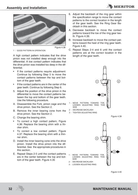
Assembly and Installation1 - Good Pattern in OperationFigure 4.38A high contact pattern indicates that the drivepinion was not installed deep enough into thedifferential. A low contact pattern indicates thatthe drive pinion was installed too deep in the differential.• If the contact patterns require adjustment:Continue by following Step 5 to move thecontact patterns between the top and bottomof the gear teeth.• If the contact patterns are in the center of thegear teeth: Continue by following Step 6.5. Adjust the position of the drive pinion in thedifferential to move the contact patterns betweenthe top and bottom of the gear teeth.Use the following procedure.A. Disassemble the Fork, pinion cage and thedrive pinion. See the Section 2.B. Remove the inner bearing cone from thedrive pinion. See the Section 2.C. Change the bearing shim.• To correct a high contact pattern, Figure4.36: Replace the bearing shim with a thickershim.• To correct a low contact pattern, Figure4.37: Replace the bearing shim with a thinnershim.D. Install the inner bearing cone onto the drivepinion. Install the drive pinion into the differential.See the appropriate procedures inthis section.E. Repeat Steps 2-5 until the contact patternsare in the center between the top and bottomof the gear teeth. Figure 4.356. Adjust the backlash of the ring gear withinthe specification range to move the contactpatterns to the correct location in the lengthof the gear teeth. See the Ring Gear Backlashin this section.A. Decrease backlash to move the contactpatterns toward the toe of the ring gear teeth.Figure 4.39.B. Increase backlash to move the contact patternstoward the heel of the ring gear teeth.Figure 4.40.C. Repeat Steps 2-4 and 6 until the contactpatterns are at the correct location in thelength of the gear teeth.1 - Move pattern toward toe,loosen adjusting ring thisside2 - Decrease Backlash3 - Tighten Adjusting Ring1 - Move pattern toward toe,loosen adjusting ring thisside2 - Decrease Backlash3 - Loosen adjusting ringFigure 4.39Figure 4.4032 <strong>MAINTENANCE</strong> <strong>MANUAL</strong>


