

MAINTENANCE MANUAL - Meritor
MAINTENANCE MANUAL - Meritor
MAINTENANCE MANUAL - Meritor
- No tags were found...

Create successful ePaper yourself
Turn your PDF publications into a flip-book with our unique Google optimized e-Paper software.
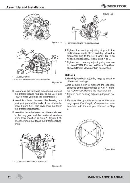
Assembly and InstallationFigure 4.25Figure 4.221 - LEVER must not touch bearings.4. Tighten the bearing adjusting ring until thedial indicator reads ZERO endplay. Move thedifferential ring to the LEFT and RIGHT asneeded. If necessary, repeat Step A or B.5. Tighten each bearing adjusting ring one notchfrom ZERO. Proceed to Check Ring GearRunout (Radial Movement) in this section.1 - lever Wrench2 - Adjusting Ring Opposite Ring GearFigure 4.233. Use one of the following procedures to movethe differential and ring gear to the LEFT andRIGHT while you read the dial indicator.A. Insert two lever between the bearing adjustingrings and the ends of the differentialcase. Figure 4.24. The lever must not touchthe differential bearings.B. Insert two lever between the differential case,or the ring gear and the carrier at locationsother than specified in Step A. Figure 4.25.The lever must not touch the differential bearings.Method 21. Hand-tighten both adjusting rings against thedifferential bearings.2. Use a micrometer to measure the oppositesurfaces of the bearing caps at X or Y. Figures4.26 e 4.27. Record the measurement3. Tighten each bearing adjusting ring one notch.4. Measure the opposite surfaces of the bearingcaps at X or Y again. Compare the measurementwith the one you obtained in Step2.Figure 4.261 - LEVER must not touch bearings.Figure 4.2428 <strong>MAINTENANCE</strong> <strong>MANUAL</strong>


