A1000 Leaflet - OMRON Russia ПРОМЭНЕРГОАВТОМАТИКА ...
A1000 Leaflet - OMRON Russia ПРОМЭНЕРГОАВТОМАТИКА ...
A1000 Leaflet - OMRON Russia ПРОМЭНЕРГОАВТОМАТИКА ...

Create successful ePaper yourself
Turn your PDF publications into a flip-book with our unique Google optimized e-Paper software.
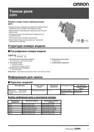
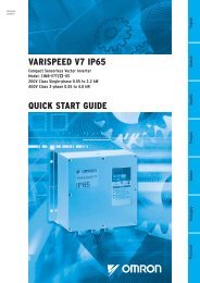
<strong>A1000</strong>High performance vector control» » Able to control IM & PM motors» »Safety built-in» »Application parameter presets
SpecificationsType designationCIMR AC4A0004 FAAAC Drive<strong>A1000</strong> seriesC: European standardspecificationsVersionCoating specs:A: StandardEnclosure, Fin:A: IP00F: IP20 / Nema 1Voltage:2: Three-phase 200 VAC4: Three-phase 400 VACA: Standard specsRated output CurrentNormal Duty0004: 3.5 [A]~0675: 675 [A]200 V classMotorkW 1 1.OutputcharacteristicsPowersupply400 V classThree-phase: CIMR-A@2A 0004 0006 0010 0012 0021 0030 0040 0056 0069 0081 0110 0138 0169 0211 0250 0312 0360 0415For HD setting 0.40 0.75 1.5 2.2 4.0 5.5 7.5 11 15 18.5 22 30 37 45 55 75 90 110For ND setting 0.75 1.1 2.2 3.0 5.5 7.5 11 15 18.5 22 30 37 45 55 75 90 110 110Inverter capacity kVA at HD 2 1.2 1.9 3 4.2 6.7 9.5 12.6 17.9 23 29 32 44 55 69 82 108 132 158Inverter capacity kVA at ND 2 1.3 2.3 3.7 4.6 8 11.4 15.2 21 26 31 42 53 64 80 95 119 137 158Rated output current (A) at HD 3.2 4 5 4 8 4 11 4 17.5 4 25 4 33 4 47 4 60 4 75 4 85 4 115 4 145 5 180 5 215 5 283 5 346 5 415 3Rated output current (A) at ND 3 3.5 6 9.6 12 21 30 40 56 69 81 110 138 169 211 250 312 360 415Max. output voltage Proportional to input voltage: 0..240 VMax. output frequency 400 HzRated input voltage and frequency 3-phase 200..240 V 50/60 HzAllowable voltage fluctuation -15%..+10%Allowable frequency fluctuation +5%Input Current (A) at HD 6 2.9 5.8 7.5 11 18.9 28 37 52 68 80 82 111 136 164 200 271 324 394Input Current (A) at ND 6 3.9 7.3 10.8 13.9 24 37 52 68 80 96 111 136 164 200 271 324 394 471Based on a standard 4-pole motor for maximum applicable motor output:2. Rated Motor Capacity is calculated with a rated output voltage of 220 V:3. Carrier frequency is set to 2kHz. Current derating is required in order to raise the carrier frequency:4. Carrier frequency can be increased up to 8 kHz while keeping this current rating. Higher carrier frequency settings require derating:5. Carrier frequency can be increased up to 5 kHz while keeping this current rating. Higher carrier frequency settings require derating:6. Assumes operation at rated output current. Input current rating varies depending on the power supply transformer, input reactor,Wiring conditions, and power supply impedance:Three-phase: CIMR-A@4A 0002 0004 0005 0007 0009 0011 0018 0023 0031 0038 0044 0058MotorFor HD setting 0.4 0.75 1.5 2.2 3.0 4.0 5.5 7.5 11 15 18.5 22kW 1 For ND setting 0.75 1.5 2.2 3.0 4.0 5.5 7.5 11 15 18.5 22 30Inverter capacity kVA at HD 2 1.4 2.6 3.7 4.2 5.5 7 11.3 13.7 18.3 24 30 34OutputcharacteristicsPowersupplyInverter capacity kVA at ND 2 1.6 3.1 4.1 5.3 6.7 8.5 13.3 17.5 24 29 34 44Rated output current (A) at HD 1.8 4 3.4 4 4.8 4 5.5 4 7.2 4 9.2 4 14.8 4 18 4 24 4 31 4 39 4 45 4Rated output current (A) at ND 3 2.1 4.1 5.4 6.9 8.8 11.1 17.5 23 31 38 44 58Max. output voltage 380..480V (proportional to input voltage)Max. output frequency 400 HzRated input voltage and frequency 3-phase 380..480 VAC, 50/60 HzAllowable voltage fluctuation -15%..+10%Allowable frequency fluctuation +5%Input Current (A) at HD 6 1.8 3.2 4.4 6 8.2 10.4 15 20 29 39 44 49Input Current (A) at ND 6 2.1 4.3 5.9 8.1 9.4 14 20 24 38 44 52 58<strong>A1000</strong> 5
SpecificationsThree-phase: CIMR-A@4A 0072 0088 0103 0139 0165 0208 0250 0296 0362 0414 0515 0675MotorFor HD setting 30 37 45 55 75 90 110 132 160 185 220 315kW 1 For ND setting 37 45 55 75 90 110 132 160 185 220 250 355Inverter capacity kVA at HD 2 48 57 69 85 114 137 165 198 232 282 343 461OutputcharacteristicsPowersupplyInverter capacity kVA at ND 2 55 67 78 106 126 159 191 226 276 316 392 514Rated output current (A) at HD 60 4 75 4 91 4 112 5 150 5 180 5 216 5 260 5 3304 370 450 605Rated output current (A) at ND 3 72 88 103 139 165 208 250 296 362 414 515 675Max. output voltage380..480V (proportional to input voltage)Max. output frequency400 HzRated input voltage and frequency3-phase 380..480 VAC, 50/60 HzAllowable voltage fluctuation -15%..+10%Allowable frequency fluctuation +5%Input Current (A) at HD 6 58 71 86 105 142 170 207 248 300 346 410 584Input Current (A) at ND 6 71 86 105 142 170 207 248 300 346 410 465 6571. Based on a standard 4-pole motor for maximum applicable motor output:2. Rated Motor Capacity is calculated with a rated output voltage of 440 V:3. Carrier frequency is set to 2kHz. Current derating is required in order to raise the carrier frequency:4. Carrier frequency can be increased up to 8 kHz while keeping this current rating. Higher carrier frequency settings require derating:5. Carrier frequency can be increased up to 5 kHz while keeping this current rating. Higher carrier frequency settings require derating:6. Assumes operation at rated output current. Input current rating varies depending on the power supply transformer, input reactor,Wiring conditions, and power supply impedance:Commom specificationsControl functionsFunctionalityProtection functionsModel numberCIMR-AControl methodsOutput frequency rangeFrequency toleranceResolution of frequency set valueResolution of output frequencyFrequency set valueStarting TorqueSpeed Control RangeSpeed Control AccuracySpeed ResponseTorque LimitAccel/Decel TimeBraking torqueV/f CharacteristicsMain Control FunctionsMotor protectionMomentary overcurrentProtectionSpecificationsSine wave PWM (V/f control, V/f control with PG, Open loop vector control, Closed loop vector control, Open loop vectorcontrol for PM, Closed loop vector control for PM, Advanced Open Loop Vector Control for PM)0.01..400 HzDigital set value: ±0.01% of the max. output frequency (-10..+40 ºC)Analogue set value: ±0.1% of the max. output frequency (25 ±10 ºC)Digital set value: 0.01 HzAnalogue set value: 0.03 Hz / 60 Hz (11 bit)0.001 Hz-10..+10 V (20 kΩ),0..10 V (20 kΩ), 4..20 mA (250 Ω),Pulse train input, frequency setting value (selectable)150%/3Hz (V/f control, V/f control with PG), 200%/0.3Hz* 1 (Open loop vector control), 200%/ 0 r/min* 1 (Closed loop vectorcontrol, Closed loop vector control for PM, Advanced Open Loop Vector Control for PM), 100% / 5% speed (Openloop vector control for PM),1:1500 (Closed loop vector control, Closed loop vector control for PM), 1:200 (Open loop vector control), 1:40 (V/f control,V/f control with PG), 1:20 (Open Loop Vector Control for PM), 1:100 (Advanced Open Loop Vector Control for PM)±0.2% in Open loop vector control (25 ±10 ºC) * 2 , 0.02% in Closed loop vector control (25 ±10 ºC)10 Hz in Open loop vector control (25 ±10 ºC), 50Hz in Closed loop Vector Control (25 ±10 ºC), )(excludes temperaturefluctuation when performing Rotational Auto-Tuning)All Vector Control allows seperate settings in four quadrants0.00 to 6000.0 s (4 selectable combinations of independent acceleration and deceleration settings)Drives of 200/400 V 30 kW or less have a built-in braking transistor.1. Short-time decel torque* 3 , over 100% for 0.4/0.75 kW motors, over 50% for 1.5 kW motors, and over 20% for 2.2 kWand above motors (over excitation braking/High-Slip Braking approx. 40%)2. Continuous regen, torque approx. 20% (approx. 125% with dynamic braking resistor option* 4 , 10% ED,10 s, internalbraking transistor)User-selected programs and V/f preset pattens possibleTorque Control, Droop control, Speed/torque control switching, Feedforward control, Zero-servo control, Momentarypower loss ride-thru, Speed search, Overtorque detection, Torque Limit, 17-step speed (max), Accel/Decel time switchS-curve Accel/Decel, 3-wire sequence, Auto-tuning (rotational, stationary), Online Tuning, Dwell Cooling fan on/offswitch, slip compensation, Torque compensation, Frequency Jump, Upper/lower limits for frequency, DC injection brakingat start and stop, Over excitation braking, High Slip braking, PID control (with sleep function), Energy saving control,MEMOBUS comm. (RS-485/422 max. 115.2kbps), Fault restart, Application presets, Removable terminal block with parameterbackup function...Motor overheat protection based on output currentDrive stops when ouput current exceeds 200% of Heavy Duty RatingOverload Protection Drive stops after 60 s at 150% of rated output current (Heavy Duty Rating)* 5Overvoltage ProtectionUndervoltage ProtectionMomentary power loss Ride-ThruHeatsink Overheat ProtectionBraking Resistance OverheatProtection200 V class: Stops when DC bus exceeds approx. 410 V, 400 V class: Stops when DC bus exceeds approx. 820V200 V class: Stops when DC bus exceeds approx. 190 V, 400 V class: Stops when DC bus exceeds approx. 380VImmediately stop after 15 ms or longer power loss (default),Continuous operation during power loss than 2 s (srandard)* 6Protected by thermisterOverheat sensor for braking resistor (optional)Stall preventionStall prevention during acceleration/deceleration and constant speed operationGround fault Protected by electronic circuit* 7Power charge indication Charge LED remains lit until DC bus has fallen below approx. 50 V.6 Frequency inverters
Ambient conditionsArea of UseIndoor (no corrosive gas, dust, etc.)Ambient Temperature -10ºC..+50ºC(open chassis) up to 60ºC with output current derating, -10ºC..+40ºC (NEMA Type 1)Ambient humidity95% RH or less (without condensation)Storage temperature-20ºC..+60ºC (short-term temperature during transportation)Altitude Up to 1000 meters (output derating of 1% per 100 m above 1000 m, max. 3000 m)Vibration / Shock10 Hz to 20 Hz, 9.8 m/s 2 max. 20 Hz to 55Hz, 5.9 m/s 2 (200 V: 45kW or more, 400 V: 55kW or more) or2.0 m/s 2 max. (200 V: 55 kW or less, 400 V: 75 kW or less)Safety StandardEN954-1 safe category 3 stop category 0; EN ISO 13849-1; IEC EN 61508 SIL2Protection DesignIP00 open-chassis, IP20, NEMA Type 1 enclosure1. Requires a drive with recommended capacity.2. Speed control accuracy may vary slightly depending on installation conditions or motor used.3. Momentary average deceleration torque refers to the deceleration torque form 60 Hz down to 0 Hz. This may vary depending on the motor.4. If L3-04 is enabled when using a braking resistor or braking resistor unit, the motor may not stop in the specified deceleration time.5. Overload protection may be triggered when operating with 150% of the rated output current, if the output frequency is less than 6 Hz.6. Varies in accordance with the drive capacity and load. Drives with a capacity of smaller than 11 kW in the 200 V (model CIMR- AA0056 or 400 V (model7.CIMR- AA0031) require a seperate Momentary Power Loss Unit to continue operating.Protection may not be provided under the following conditions as the motor windings are grounded internally during run: #Low resistance to ground fromthe motor cable or terminal block. #Drive already has a short-circuit when the power is turned on.DimensionsOpen-Chassis [IP00]W1 4-dt2W14-dt2W14-dt2H1HH1HH1HMax 10WH2Max 10Figure 1Dt1D1Max 7.7H2W Max 7.7DD1t1Max 6WH2Max 6DD1t1Figure 2Figure 3Voltage classThree-phase200 VThree-phase400 VMax. applicableDimensions in mmmotor output kW Inverter modelCIMR-A@FigureND HD W H D W1 H1 H2 D1 t1 t2 d30 22 0110250 400195 3852125810037 30 0138 275 450 220 435 257.52.3 2.3 M645 37 016937325 550 283 260 535 11055 45 0211 38175 55 025076450 705 330 325 680 12.53.2 3.2 M1090 75 0312 80130110 90 036098500 800 350 370 773 13 4.5 4.5 M12110 110 0415 9930 22 0058250 400195 385211002.337 30 0072 275 450 220 435 2525845 37 008836510495 7.5 105 2.3 3.2 M655 45 0103 3632526075 55 0139411550 283 535 110 2.390 75 0165 42110 90 0208 450 705 330 325 680 12.5132 110 025096130160 132 0296 800 35077310250037013185 160 0362 1074.5 4.5 M12220 185 0414 2 950923 135 125Weight(kg)3.2 3.2 M10 79250 220 05153702163 670 1140 440 1110 15 150355 315 0675 221<strong>A1000</strong> 7
Enclosed Panel [NEMA Type1]W14-d1.5W14-d1.5WH2H15 Ht1D1DWH1H3H2Figure 1 Figure 2H8Dt1D1Voltage classThree-phase200 VThree-phase400 VMax. applicablemotor output kWDimensions in mmInverter modelFigureCIMR-A@ND HD W H D W1 H1 H2 D1 t1 t2 d0.75 0.4 00041.1 0.75 0006 3.1147382.2 1.5 0010 3.23 2.2 0012 140 260122 248 63.2M55.5 4.0 0021 11643.55 -7.5 5.5 0030554.016711 7.5 0040 4.015 11 0056 180 300 187 160 28418.5 15 006935088.7220197 192 335 78 M622 18.5 0081 2 365 9.70.75 0.4 0002Weight(kg)3.175 5.61.5 0.75 0004 147383.22.2 1.5 0005 3.23 2.2 00073.4140 260122 248 64.0 3 0009 1643.5M55.5 4.0 0011 15 -3.5557.5 5.5 00183.911 7.5 0023 1673.915 11 00315.4180 300 160 28418.5 15 0038 187 8 75 5.722 18.5 0044 220 350 197 192 335 78 M6 8.33.2Schaffner Flat FiltersCFEAEBFigure 1Figure 2200 V400 VFlat Filters3G3RV-PFI2035-SEFig Dimensions WeightKGA B C D E F G H I L330 141 46 281 313 115 5.5 M5 23 M5 1.43G3RV-PFI2060-SE 1 355 206 60 302 336 175 6.5 M6 30 M6 33G3RV-PFI2100-SE 408 236 80 355 390 205 6.5 M6 40 M6 4.93G3RV-PFI3010-SE330 141 46 281 313 115 5.5 M4 23 M5 1.23G3RV-PFI3018-SE 330 141 46 281 313 115 5.5 M4 23 M5 1.313G3RV-PFI3035-SE 355 206 50 302 336 175 6.5 M5 25 M6 2.23G3RV-PFI3060-SE 408 236 65 355 390 205 6.5 M6 32.5 M6 43G3RV-PFI3410-SE386 115 260 - 120 235 12.0 M12 - - 8.53G3RV-PFI3600-SE 2 386 135 260 - 120 235 12.0 M12 - - 11.03G3RV-PFI3800-SE 564 160 300 - 210 275 9.0 M12 - - 31.08 Frequency inverters
Bookform FiltersDCHBAEGF200 V400 VBookform FiltersDimensionsA B C D E F G H3G3RV-PFI2130-SE 310 180 90 280 295 65 6.5 M10 4.33G3RV-PFI2160-SE 380 170 120 350 365 102 6.5 M10 6.03G3RV-PFI2200-SE 518 240 130 480 498 90 8.2 M10 11.03G3RV-PFI3070-SE 329 185 80 300 314 55 6.5 M6 3.43G3RV-PFI3130-SE 310 180 90 280 295 65 6.5 M10 4.73G3RV-PFI3170-SE 380 170 120 350 365 102 6.5 M10 6.03G3RV-PFI3250-SE 610 240 130 480 498 90 8.3 M10 11.73G3RV-PFI3410-SE 386 115 260 - 120 235 12.0 M12 8.53G3RV-PFI3600-SE 386 135 260 - 120 235 12.0 M12 11.03G3RV-PFI3800-SE 564 160 300 - 210 275 9.0 M12 31.0WeightKGRemote LCD operator12.2(0.48)1.6 (0.06)Installation holes(2-M3 screws, depth 5 (0.19))90 (3.54)78 (3.07)15(0.59)60 (2.36) 7.9(0.31)minimum 50 (1.96)44 (1.73)Unit : mm (in)ChokesXDescriptionDdiameterMotorKWDimensionsWeightKgL W H X Y m<strong>A1000</strong>-FEV2102-RE 21 < 2.2 85 22 46 70 - 5 0.1<strong>A1000</strong>-FEV2515-RE 25 < 15 105 25 62 90 - 5 0.2<strong>A1000</strong>-FEV5045-RE 50 < 45 150 50 110 125 30 5 0.7<strong>A1000</strong>-FEV6045-RE 60 > 45 200 65 170 180 45 6 1.7W YHLØ dØ m<strong>A1000</strong> 9
Braking UnitModel CDBR-2015 B, -2022 B, -4030B, -4045 BModel CDBR-2110 B30 ormore4-M4 MTG Holes 7238128140383-lead Wire Inlet(20 Dia. Rubber Bush)138150114.530 ormore 138.566.5100 or more100 or more3703501231736.57330ormore10059140Main CircuitTerminalM65014018030ormore4-M6MTG Holes104111156200100 or less 100 or lessLead Wire Inlet(28 Dia. Rubber Bush)2-lead Wire Inlet(35 Dia. Rubber Bush)Mass 1.8 KMass 8.5 KgModel CDBR-4220 B370355931736.57030ormore156.5210Main CircuitTerminalM64-M6MTG Holes104118.5 5011130210156or250 more200100 or more 100 or moreLead Wire Inlet(28 Dia. Rubber Bush)2-lead Wire Inlet(35 Dia. Rubber Bush)Mass 12 KgResistor Dimensions<strong>A1000</strong>-REJ0K15___<strong>A1000</strong>-REJ0K10___16811.518227105453620Braking Resistor UnitVoltage220 VClass400 VClassModelLKEB-_Dimensions in mmMasskgA B C D MTG Screw21P522P2 130 350 75 335 M5 x 34.523P7 5.025P57.5250 350 200 335 M6 x 427P5 8.52011 266 543 246 340 M8 x 4 102015 356 543 336 340 M8 x 4 1520182022446 543 426 340 M8 x 4 1941P542P2130 350 75 335 M5 x 4 4.543P7 130 350 75 335 M5 x 4 5.045P57.5250 350 200 335 M6 x 447P5 8.5401116350 412 330 325 M6 x 44015 1840184022446 543 426 340 M8 x 4 194030 356 956 336 740 M8 x 4 254037 446 956 426 740 M8 x 4 334045 446 956 426 740 M8 x 4 33C30 or more A30 or moreMTG ScrewCMTG Screw50 or more A50 or moreDBDB150260150 or more 150 or more200 or more 200 or more10 Frequency inverters
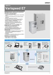
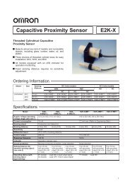
InstallationStandard connectionsTerminals -, +1, +2, B1, B2 arefor connection options. Neverconnect power supply lines tothese terminalsDC reactor(option)UXJumperThermal relay(option)Braking resistor(option)Three-phasepower supply200 to 400 V50/60 HzR/L1S/L2T/L3MainSwitchFuseMulti-functiondigtial inputs(default setting)EMCFilterForward Run / StopReverse Run / StopExternal faultFault resetMulti-speed step 1Multi-speed step 2Jog speedExternal BaseblockSink / Source modeselection wire link(default: Sink)R/L1S/L2T/L3S1S2S3S4S5S6S7S8SNSCSP+24 V+ 2 + 1 B1 B2Main CircuitControl Circuit<strong>A1000</strong>Option card connectorsCN5-CCN5-BCN5-ATerminal boardjumpers and switchesDIP Switch S1V IA2 Volt/Curr. SelOffPTCAIDIP Switch S2OnTerm. Res. On/OffJumper S3H1, H2Sink/Source Sel.DIP Switch S4A3 Analog/PTCInput SelJumper S5VAM/FM Volt./Curr.I SelectionU/T1V/T2W/T3GroundShieldedCableUVWMotorMMulti-functionanalog/ pulsetrain inputsSafetyswitchS2S1OpenSafety relay /controller2 kΩMEMOBUS/Modbuscomm. RS485/422max. 115.2 kBpsRPA2A3 Analog Input 3 / PTC Input (Aux. frequencyreference)AC -10 to +10 Vdc (20 kΩ)0 V−V Power supply, -10.5 Vdc, max. 20 mATermination resistor(120 Ω, 1/2 W)R+RS+SIGSafe Disable inputs H1Wirejumper+V Power supply +10.5 Vdc, max. 20 mAA1 Analog Input 1 (Frequency Reference Bias)-10 to +10 Vdc (20 kΩ)H2HCFM AMShield ground terminalPulse Train Input (max 32 kHz)Analog Input 2 (Frequency Reference Bias)-10 to +10 Vdc (20 kΩ)0 or 4 to 20 mA (250 Ω)DIPSwitch S20 V0 VMAMBMCM1M2M3M4M5M6MPACFMAMACE (G)EDM (Safety Electronic Device Monitor)DM+DMFault relay output250 Vac, max. 1 A30 Vdc, max 1 A(min. 5 Vdc, 10 mA)Multi-function relay output (During Run)250 Vac, max. 1 A30 Vdc, max 1 A(min. 5 Vdc, 10 mA)Multi-function relay output (Zero Speed)250 Vac, max. 1 A30 Vdc, max 1 A(min. 5 Vdc, 10 mA)Multi-function relay output (Speed Agree 1)250 Vac, max. 1 A30 Vdc, max 1 A(min. 5 Vdc, 10 mA)Multi-function pulse train output(Output frequency)0 to 32 kHz (2.2 kΩ) +FM AM+Multi-function analog output 1(Output frequency)-10 to +10 Vdc (2mA) or 4 to 20 mAMulti-function analog output 2(Output current)-10 to +10 Vdc (2mA) or 4 to 20 mAshielded linetwisted-pair shielded linecontrol circuit terminalmain circuit terminalMain circuitTerminal Name Function (signal level)R/L1, S/L2, T/L3 Main circuit power supply input Used to connect line power to the drive.U/T1, V/T2, W/T3 Inverter output Used to connect the motorB1, B2 Braking resistor connection Available for connecting a braking resistor or the braking resistor unit option.+2, +1 DC reactor connection Remove the short bar between +2 and +1 when connecting DC reactor (option)+1, – DC power supply input For power supply input (+1: positive electrode; – : negative electrode)*+3 Braking Unit Connection for Braking Unit between terminals +3 and –GroundingFor grounding (grounding should conform to the local grounding code.)<strong>A1000</strong> 11
Control CircuitType No. Signal name Function Signal levelS1 Multi-function input selection 1 Factory setting: runs when CLOSED, stops when OPEN.S2 Multi-function input selection 2 Factory setting: runs when CLOSED, stops when OPEN.Digital input signalsS3 Multi-function input selection 3 Factory setting: External Fault (N.O.)S4 Multi-function input selection 4 Factory setting: Fault resetS5 Multi-function input selection 5 Factory setting: Multi-step speed cmd 1S6 Multi-function input selection 6 Factory setting: Multi-step speed cmd 2S7 Multi-function input selection 7 Factory setting: Jog Frequency24 VDC, 8 mAphotocouplerinsulationS8 Multi-function input selection 8 Factory setting: Closed gives external baseblockSCMulti-function input selectionCommonCommon for control signal+V Power Supply for Frequency Setting +10.5 V (allowable max current 20 mA)Analog input signalsSafety Input–V Power Supply for Frequency Setting –10.5 V (allowable max current 20 mA)A1 Multi-function analogue input 1 Main Frequency Reference -10 to +10 VDC, 0 to +10 VDC (20 kΩ)A2 Multi-function analogue input 2Voltage input or current input-10 to +10 VDC, 0 to +10 VDC (20 kΩ)4 to 20 mA (250 Ω)A3 Multi-function analogue input 3 –10 to +10 V, 0 to +10 V (20 kΩ)AC Frequency reference common 0VHC Safety Input Common +24 V (max allowable current 10 mA)H1 Safety Input 1H2 Safety Input 2Open: StopClosed: Normal OperationPhotocoupler 24 VDC, 8 mASafetymonitoroutputDM+DM–Safety monitor outputSafety monitor output commonOpen: Safety inputs 1 and 2 are open48 Vdc, 50mA or lessMANO contact outputDigital output signalsAnalog outputsignalsPulseI/OMB NC OutputFactory setting: "fault"MC Relay Output commonM1Multi-function contact output (N.O ) Factory setting Closed: During runM2P1 Photocoupler output 1 Factory setting: Zero speedP2 Photocoupler output 2 Factory setting: Frequency AgreePC Photocoupler output common 0VFM Multi-function analog monitor (1) Factory setting: Output frequencyAM Multi-function analog monitor (2) Factory setting: "Current monitor, 5 V/drive rated currentAC Analog monitor common 0VRP Main Speed Cmd Pulse Train Input 32 kHz max. (3 kΩ)MP Pulse Train Output Factory setting: Frequency reference input (H6-01=0) 0 to 33 kHz (2.2 kΩ)Contact capacity250 VAC,1 A or less30 VDC, 1 Aor lessPhotocoupler output:+48 VDC, 50 mA orless–10 to 10 V ±5%,(2 mA or less)0 to 10 V4 - 20 mAR+ Communication input (+)RS-485/422R– Communication input (–)S+ Communication output (+)S– Communication output (–)For MEMOBUS communicationoperation by RS-485 or RS-422 communication is available.RS-485/422MEMOBUSprotocol12 Frequency inverters
Inverter heat lossThree-phase 200 V classModel NumberCIMR-ARated Amps (A)Heatsink Loss(W)Heavy DutyInterior UnitLoss (W)Total Loss (W) Rated Amps (A)Heatsink Loss(W)Normal DutyInterior UnitLoss (W)Total Loss (W)2A0004 3.2 14.8 44 59 3.5 18.4 47 662A0006 5.0 24 48 72 6.0 31 51 822A0010 8.0 43 52 95 9.6 57 58 1152A0012 11.0 64 58 122 12.0 77 64 1412A0021 17.5 101 67 168 21 138 83 2222A0030 25 194 92 287 30 262 117 3792A0040 33 214 105 319 40 293 145 4372A0056 47 280 130 410 56 371 175 5462A0069 60 395 163 558 69 491 205 6962A0081 75 460 221 681 81 527 257 7852A0110 85 510 211 721 110 719 286 10052A0138 115 662 250 912 138 842 312 11542A0169 145 816 306 1122 169 1014 380 13942A0211 180 976 378 1354 211 1218 473 16912A0250 215 1514 466 1980 250 1764 594 23582A0312 283 1936 588 2524 312 2020 665 26862A0360 346 2564 783 3347 360 2698 894 35912A0415 415 2672 954 3626 415 2672 954 3626Three-phase 400 V classModel NumberCIMR-ARated Amps (A)Heatsink Loss(W)Heavy DutyInterior UnitLoss (W)Total Loss (W) Rated Amps (A)Heatsink Loss(W)Normal DutyInterior UnitLoss (W)Total Loss (W)4A0002 1.8 15.9 45 61 2.1 20 48 684A0004 3.4 25 46 70 4.1 32 49 814A0005 4.8 37 49 87 5.4 45 53 974A0007 5.5 48 53 101 6.9 62 59 1214A0009 7.2 53 55 108 8.8 66 60 1264A0011 9.2 69 61 130 11.1 89 73 1624A0018 14.8 135 86 221 17.5 177 108 2854A0023 18.0 150 97 247 23 216 138 3544A0031 24 208 115 323 31 295 161 4554A0038 31 263 141 403 38 340 182 5214A0044 39 330 179 509 44 390 209 5994A0058 45 349 170 518 58 471 215 6864A0072 60 484 217 701 72 605 265 8704A0088 75 563 254 817 88 684 308 9934A0103 91 723 299 1022 103 848 357 12054A0139 112 908 416 1325 139 1215 534 17494A0165 150 1340 580 1920 165 1557 668 22244A0208 180 1771 541 2313 208 1800 607 24084A0250 216 2360 715 3075 250 2379 803 31824A0296 260 2391 787 3178 296 2448 905 33534A0362 304 3075 985 4060 362 3168 1130 42984A0414 370 3578 1164 4742 414 3443 1295 47384A0515 450 3972 1386 5358 515 4850 1668 65184A0675 605 4191 1685 5875 675 4861 2037 6898<strong>A1000</strong> 13
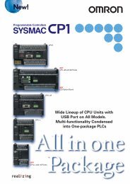
Connections for braking unit and braking resistorPowersupplyMCCBMCThermalrelayR/L1B1 B2S/L2U/T1T/L3V/T2Braking resistorMotor+ 3−Braking ResistorOverheat Contact(Thermal Relay Trip Contact)1P2BBrakingResistorUnitTHRX OFFSAThermal relay switch forexternal braking resistorMCONMCSAMCTHRXTRXSATRXFLT-A FLT-BFault contact<strong>A1000</strong>W/T3<strong>A1000</strong>−12Level Detector+ + 0 − 0MASTERSLAVEBraking Unit 13 4+1556Cooling Fin Overheat Contact(Thermoswitch Contact)AC reactorAC reactor<strong>A1000</strong>Power supplyMCCBUXR/L1VYS/L2WZT/L3200 V class 400 V classCurrent valueInductanceMax. applicableCurrent valueAmHmotor output kWA0.4 2.5 4.2 0.4 1.3 180.75 5 2.1 0.75 2.5 8.41.5 10 1.1 1.5 5 4.22.2 15 0.71 2.2 7.5 3.64.0 20 0.53 4.0 10 2.25.5 30 0.35 5.5 15 1.427.5 40 0.265 7.5 20 1.0611 60 0.18 11 30 0.715 80 0.13 15 40 0.5318.5 90 0.12 18.5 50 0.4222 120 0.09 22 60 0.3630 160 0.07 30 80 0.2837 200 0.05 37 90 0.2445 240 0.044 45 120 0.1855 280 0.039 55 150 0.1575 360 0.026 75 200 0.1190 500 0.02 90/110 250 0.09110 600 0.02 132/160 330 0.06- 160/185/220 490 0.04315 660 0.03Max. applicablemotor output kWInductancemHDC reactorPowersupplyMCCBR/L1<strong>A1000</strong>S/L2T/L3+1 +2DC reactor200 V class 400 V classMax. applicablemotor output kWCurrent valueAInductancemHMax. applicablemotor output kWCurrent valueAInductancemH0.40.45.4 80.75 0.753.2 281.51.52.2 18 32.25.7 114.0 4.0 12 6.35.55.536 17.5 7.523 3.6111172 0.515 1533 1.918.5 90 0.4 18.5 47 1.322 to 110 Built-in 22 to 315 Built-in14 Frequency inverters
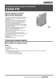
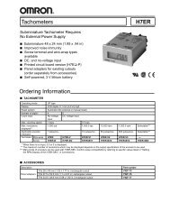
Safety System• <strong>A1000</strong> provides Safe Torque Off (STO)functional safety in compliance withEN954-1 safety category 3 stopcategory 0, EN ISO 13849-1, PLC,IEC/EN61508 SIL2.• An External Device Monitor (EDM)function has also been added tomonitor the safety status of the drive.EN954-1 Safety Cat.3ComplianceSafetycontrollerControllerPowersupplyFeedback loopMotor<strong>A1000</strong> 15
CopyLOCKYASKAWAOrdering informationPowerSupplyMCCBCCommunications cable with PCAC ReactorAFilterVerifyReadUSB Copy UnitCOM ERRJVOP-181CRJ-45 / USBAdapterCRemote OperatorExtansion CableCUSB CableCLCD RemoteOperatorDCX-DriveCX-OneC24 VDC Control Board Power Supply<strong>A1000</strong>BCommunication Option BoardAChokeFFeedback Speed Option CardsMotorEBraking ResistorGroundDC Reactor<strong>A1000</strong>200 V400 VSpecificationsModelHeavy Duty Normal Duty Standard0.4 kW 3.2 A 0.75 kW 3.5 A CIMR-AC2A0004FAA0.75 kW 5.0 A 1.1 kW 6.0 A CIMR-AC2A0006FAA1.5 kW 8.0 A 2.2 kW 9.6 A CIMR-AC2A0010FAA2.2 kW 11.0 A 3.0 kW 12.0 A CIMR-AC2A0012FAA4.0 kW 17.5 A 5.5 kW 21.0 A CIMR-AC2A0021FAA5.5 kW 25.0 A 7.5 kW 30.0 A CIMR-AC2A0030FAA7.5 kW 33.0 A 11.0 kW 40.0 A CIMR-AC2A0040FAA11 kW 47.0 A 15.0 kW 56.0 A CIMR-AC2A0056FAA15 kW 60.0 A 18.5 kW 69.0 A CIMR-AC2A0069FAA18.5 kW 75 A 22 kW 81 A CIMR-AC2A0081FAA22 kW 85 A 30 kW 110 A CIMR-AC2A0110AAA30 kW 115 A 37 kW 138 A CIMR-AC2A0138AAA37 kW 145 A 45 kW 169 A CIMR-AC2A0169AAA45 kW 180 A 55 kW 211 A CIMR-AC2A0211AAA55 kW 215 A 75 kW 250 A CIMR-AC2A0250AAA75 kW 283 A 90 kW 312 A CIMR-AC2A0312AAA90 kW 346 A 110 kW 360 A CIMR-AC2A0360AAA110 kW 415 110 kW 415 A CIMR-AC2A0415AAA0.4 kW 1.8 A 0.75 kW 2.1 A CIMR-AC4A0002FAA0.75 kW 3.4 A 1.5 kW 4.1 A CIMR-AC4A0004FAA1.5 kW 4.8 A 2.2 kW 5.4 A CIMR-AC4A0005FAA2.2 kW 5.5 A 3.0 kW 6.9 A CIMR-AC4A0007FAA3.0 kW 7.2 A 4.0 kW 8.8 A CIMR-AC4A0009FAA4.0 kW 9.2 A 5.5 kW 11.1 A CIMR-AC4A0011FAA5.5 kW 14.8 A 7.5 kW 17.5 A CIMR-AC4A0018FAA7.5 kW 18.0 A 11.0 kW 23.0 A CIMR-AC4A0023FAA11 kW 24.0 A 15.0 kW 31.0 A CIMR-AC4A0031FAA15 kW 31.0 A 18.5 kW 38.0 A CIMR-AC4A0038FAA18.5 kW 39 A 22 kW 44 A CIMR-AC4A0044FAA22 kW 45 A 30 kW 58 A CIMR-AC4A0058AAA30 kW 60 A 37 kW 72 A CIMR-AC4A0072AAA37 kW 75 A 45 kW 88 A CIMR-AC4A0088AAA45 kW 91 A 55 kW 103 A CIMR-AC4A0103AAA55 kW 112 A 75 kW 139 A CIMR-AC4A0139AAA75 kW 150 A 90 kW 165 A CIMR-AC4A0165AAA90 kW 180 A 110 kW 208 A CIMR-AC4A0208AAA110 kW 216 A 132 kW 250 A CIMR-AC4A0250AAA132 kW 260 A 160 kW 296 A CIMR-AC4A0296AAA160 kW 304 A 185 kW 362 A CIMR-AC4A0362AAA185 kW 370 A 220 kW 414 A CIMR-AC4A0414AAA220 kW 450 A 250 kW 515 A CIMR-AC4A0515AAA315 kW 605 A 355 kW 675 A CIMR-AC4A0675AAA16 Frequency inverters
A Line filtersChokesB Communication cardsC AccessoriesInverterLine filterVoltage Model CIMR-A Reference Rated current (A) Weight (kg)3-Phase 200 VAC3-Phase 400 VACCommunicationoption board2CA0004 / 2CA0006 / 2CA0008 3G3RV-PFI3010-SE 10 1.22CA0010 / 2CA0012 / 2CA0018 / 2CA0021 3G3RV-PFI3018-SE 18 1.32CA0030 / 2CA0040 / 2CA0056 3G3RV-PFI2035-SE 35 1.42CA0069 / 2CA0081 3G3RV-PFI2060-SE 60 32CA00110 / 2CA0138 3G3RV-PFI2100-SE 100 4.92CA0169 / 2CA0211 3G3RV-PFI3170-SE 170 6.04CA0002 /4CA0004 / 4CA0005 / 4CA0007 3G3RV-PFI3010-SE 10 1.24C0009 /4C0011 3G3RV-PFI3018-SE 18 1.34CA0018 / 4CA0023 / 4CA0031 3G3RV-PFI3035-SE 35 2.24CA0038 /4CA0044 / 4CA0058 3G3RV-PFI3060-SE 60 4.04CA0072 /4CA0088 3G3RV-PFI3100-SE 100 4.54CA0103 / 4CA0139 / 4CA0165 3G3RV-PFI3170-SE 170 6.04CA0208 / 4CA0250 3G3RV-PFI3200-SE 250 114CA0296 / 4CA0362 3G3RV-PFI3400-SE 400 8.54CA0414 / 4CA0515 3G3RV-PFI3600-SE 600 11.04CA0675 3G3RV-PFI3800-SE 800 31.0Model Diameter Description<strong>A1000</strong>-FEV2102-RE 21 Recommended for motors below 2.2 KW<strong>A1000</strong>-FEV2515-RE 25 Recommended for motors below 15 KW<strong>A1000</strong>-FEV5045-RE 50 Recommended for motors below 45 KW<strong>A1000</strong>-FEV6045-RE 60 Recommended for motors above 45 KWType Model Description Function• Used for running or stopping the inverter, setting or referencing parameters, and monitoringSI-N3DeviceNet option cardoutput frequency, output current, or similar items through DeviceNet communi-cation with the host controller.• Used for running or stopping the inverter, setting or referencing parameters, and monitoringSI-P3PROFIBUS-DP option cardoutput frequency, output current, or similar items through PROFIBUS-DP com-munication with the host controller.SI-S3SI-T3Can open option cardMechatrolink II option card• Used for running or stopping the inverter, setting or referencing parameters, and monitoringoutput frequency, output current, or similar items through CANopen communicationwith the host controller.• Used for running or stopping the inverter, setting or referencing parameters, and monitoringoutput frequency, output current, or similar items through Mechatrolink II communicationwith the host controller.Types Model Description FunctionsJVOP-180 LCD remote operator LCD Display operator with language supportDigitaloperator3G3AX-CAJOP300-EE Remote operator cable 3 meters cable for connecting remote operatorJVOP-181 USB converter / USB cable USB converter unit with copy and backup functionAccessoriesPS-V10S24V DC control board power supply VZA-B/2/4 from 0.1 to 4 KW24 VDC option boardPS-V10M24V DC control board power supply VZA-2/4 from 5.5 to 15 KW<strong>A1000</strong>-CAVPC232-EE PC connection cable RS232 PC tool connection cableD Computer softwareTypes Model Description InstallationSoftwareCX-drive Computer software Configuration and monitoring software toolCX-One Computer software Configuration and monitoring software tool<strong>A1000</strong> 17
E Braking unit, braking resistor unitInverterMax.ApplicableMotor kW200 V Class400 V ClassModelCIMR-A@2A_Braking unitModelCDBR_No. ofusedModel<strong>A1000</strong>-RE_Specifications ofResistorQtyBraking Resistor 1Typetorque Braking%Model(3% ED)LKEB-Specifications ofResistorQtytorque Braking Min% Resist(10% ED) Value Ω0.4 0004 HD220 - - − - - 480.750004 ND- - − - -J0K15200-IE 190W 200 Ω 1 1250006 HD - - − - -481.10006 ND 85 - - − - -0008 HD150 21P5 260W 100Ω 1 150481.50008 NDJ0K15100-IE 190 W 100 Ω 11125 21P5 260W 100Ω0010 HD 1125 482.20010 ND148J0K15070-IE 190 W 70 Ω 1 120 22P2 260W 70Ω1200012 HD 1 160012 ND13100 23P7 390W 40Ω150 160018 HDJ0K15062-IE 190 W 62 Ω 1 10018 ND13.780 23P7 390W 40Ω125 160021 HD 15.50021 ND 2 1101Built-in25P5 520W 30Ω0030 HD - 1115 167.50030 ND -11627P5 780W 20Ω1250040 HD - 1 9.6110040 ND -12011 2400W 13.6Ω0056 HD - 1125 9.6150056 ND -12015 3000W 10Ω0069 HD - 1125 9.618.50069 ND -12015 3000W 10Ω0081 HD - 1100 9.6220081 ND - 2015 3000W 10Ω 1 85 9.60110 HD - 2022 4800W 6.8Ω 1 125 6.4300110 ND -12022 4800W 6.8Ω0138 HD - 190 6.4370138 ND - 2022 4800W 6.8Ω 1 70 6.40169 HD 2015B 2 - 2015 3000W 10Ω 2 100 9.6450169 ND - 2015 3000W 10Ω 2 802022B 20211 HD - 2022 4800W 6.8Ω 2 1206.4550211 ND -6.42022B 2 2022 4800W 6.8Ω 2 1000250 HD - 6.4750250 ND -2110B 10312 HD -2022 4800W 6.8Ω 3 110 1.6900312 ND -2110B 10360 HD -2022 4800W 6.8Ω 4 120 1.61100360 ND -2110B 10415 HD -2018 4800W 8Ω 5 100 1.60.4 0002 HDJ0K10750-IE 60 W 750 Ω 1 230 - - - - - 960.750002 ND- - - - -J0K10750-IE 60 W 750 Ω 1 1300004 HD - - - - -961.50004 ND96J0k15400-IE 190 W 400 Ω 1 125 41P5 260W 400Ω 1 1250005 HD 642.20005 ND0007 HDJ0k15300-IE 190 W 300 Ω 1 115 42P2 260W 250Ω 1 135 6430007 ND42P2 260W 250Ω 1 100 64J0k15200-IE 190 W 200 Ω 1 1250009 HD 43P7 390W 150Ω 1 150 323.70009 ND0011 HDJ0k15200-IE 190 W 200 Ω 1 105 43P7 390W 150Ω 1 135 325.50011 ND J0k15200-IE 190 W 100 Ω 2 1350018 HD -45P5 520W 100Ω 1 135 327.50018 ND Built in-0023 HD -47P5 780W 75Ω 1 130 32110023 ND -324011 1040W 50Ω 1 1350031 HD - 20150031 ND -0038 HD -4015 1560W 40Ω 1 125 2018.50038 ND -204018 4800W 32Ω 1 1250044 HD - 19.2220044 ND -0058 HD -4022 4800W 27.2Ω 1 125 19.2300058 ND -0072 HD -4030 6000W 20Ω 1 125 19.2370072 ND - 4030 6000W 20Ω 1 100 19.80088 HD 4045B 1 - 4037 9600W 16 1 125 12.8450088 ND -4045B 10103 HD -4045 9600W 13.6Ω 1 125 12.8550103 ND 4045B 2 - 4045 9600W 13.6Ω 1 100 12.80139 HD 4030B 2 - 4030 6000W 20Ω 2 135 19.2750139 ND 4030B 2 - 4030 6000W 20Ω 2 100 19.20165 HD 4045B 2 - 4045 9600W 13.6Ω 2 145 12.8900165 ND -4045B 20208 HD -4045 9600W 13.6Ω 2 120 12.81100208 ND -4220B 10250 HD -4030 6000W 20Ω 3 100 3.218 Frequency inverters
InverterBraking unitBraking Resistor 1TypeMax. ModelModel No. of Model Specifications ofBrakingModel Specifications ofBraking MinApplicable CIMR-QtyCDBR_ used <strong>A1000</strong>-RE_ Resistortorque %QtyLKEB- Resistortorque % ResistMotor kW A@2A_(3% ED)(10% ED) Value Ω1320250 ND -4220B 10296 HD -4045 9600W 13.6Ω 4 140 3.21600296 ND -4220B 10362 HD -4045 9600W 13.6Ω 4 120 3.21850362 ND -4220B 10414 HD -4045 9600W 13.6Ω 4 100 3.22200414 ND 1 -4220B0515 HD -4037 9600W 16Ω 5110 3.2250 0515 ND 4220B 1 - 95 3.2315 0675 HD 4220B 2 -1054045 9600W 13.6Ω 6355 0675 ND 4220B 2 - 903.2400 V Class1. When connecting a mounting type resistor or braking resistor unit, set system constant L3-04 to 0 (Stall prevention disabled during deceleration). Motorwill not stop at set deceleration time if this constant is not changed. Additionally the Internal braking transistor protection (L8-55) should be set to “0” whena external braking unit (CDBR-) is used.F Feedback speed option cardType Model Description FunctionPG-B3 Complementary PG • For speed feedback input by connecting a motor encoderInput: 3 track (one or two tracks), for HTL encoder connection, 50 KHz maxOutput: 3 track open collectorEncoder power supply: 12 V, 200 mA maxPG-X3 Line Driver PG • For speed feedback input by connecting a motor encoderInput: 3 track, line driver, 300 kHz maxOutput: 3 track, line driverEncoder power supply: 5 V or 12 V, 200 mA maxPG option cardALL DIMENSIONS SHOWN ARE IN MILLIMETERS.To convert millimeters into inches, multiply by 0.03937. To convert grams into ounces, multiply by 0.03527.Cat. No. I79E-EN-01In the interest of product improvement, specifications are subject to change without notice.<strong>A1000</strong> 19