Cadence OrCAD FPGA System Planner
Cadence OrCAD FPGA System Planner
Cadence OrCAD FPGA System Planner

You also want an ePaper? Increase the reach of your titles
YUMPU automatically turns print PDFs into web optimized ePapers that Google loves.
create initial pin assignment that accounts<br />
for <strong>FPGA</strong> placement on the PCB (placement-aware<br />
pin assignment synthesis).<br />
This unique placement-aware pin assignment<br />
approach eliminates unnecessary<br />
physical design iterations that are inherent<br />
in manual approaches.<br />
The <strong>OrCAD</strong> <strong>FPGA</strong> <strong>System</strong> <strong>Planner</strong> is integrated<br />
with both <strong>OrCAD</strong> Capture and<br />
<strong>OrCAD</strong> PCB Editor. It reads and creates<br />
Capture schematics and symbols. In<br />
addition, a floorplan view uses existing<br />
footprint libraries from <strong>OrCAD</strong> PCB Editor.<br />
Should placement change during layout,<br />
pin optimization using <strong>FPGA</strong> <strong>System</strong><br />
<strong>Planner</strong> can be accessed directly from<br />
<strong>OrCAD</strong> PCB Editor.<br />
Benefits<br />
• Scalable, cost-effective <strong>FPGA</strong>-PCB<br />
co-design solution from <strong>OrCAD</strong> to<br />
Allegro ® GXL<br />
• Shortens time for optimum initial pin<br />
assignment, accelerating PCB design<br />
schedules<br />
• Accelerates integration of <strong>FPGA</strong>s<br />
with <strong>OrCAD</strong> PCB design creation<br />
environments<br />
• Eliminates unnecessary, frustrating<br />
design iterations during the PCB layout<br />
process<br />
• Eliminates unnecessary physical<br />
prototype iterations due to <strong>FPGA</strong> pin<br />
assignment errors<br />
• Reduces PCB layer count through<br />
placement aware pin assignment and<br />
optimization<br />
Features<br />
<strong>OrCAD</strong> <strong>FPGA</strong> <strong>System</strong> <strong>Planner</strong><br />
Technology<br />
An <strong>FPGA</strong> system is defined as a subset of<br />
the PCB design that includes one or more<br />
<strong>FPGA</strong> and non-<strong>FPGA</strong> components that are<br />
connected to <strong>FPGA</strong>s.<br />
Traditional approaches to pin assignment<br />
are typically manual and often based<br />
on a spreadsheet. Tools such as these<br />
require users to do pin assignment without<br />
taking into consideration the placement<br />
of other components and routability<br />
of the interfaces and signals. Above<br />
<strong>Cadence</strong> <strong>OrCAD</strong> <strong>FPGA</strong> <strong>System</strong> <strong>Planner</strong><br />
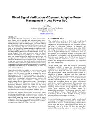
Figure 2: Placement/Floorplan view of the <strong>OrCAD</strong> <strong>FPGA</strong> <strong>System</strong> <strong>Planner</strong> provides users relative<br />
placement of critical components for optimum pin assignment synthesis<br />
all, there is no online rules-checking to<br />
ensure that the right pin types are being<br />
used for the signals that are assigned to<br />
the <strong>FPGA</strong> pins. As a result, users have<br />
to make several iterations between the<br />
spreadsheet-based tools and the tools<br />
from <strong>FPGA</strong> vendors. Often this adds an<br />
increased number of iterations between<br />
the PCB layout designer who cannot<br />
route the signals from <strong>FPGA</strong> pins on<br />
available layers and the <strong>FPGA</strong> designer<br />
who has to accept paper-based or verbal<br />
pin-assignment suggestions from the<br />
PCB layout designer. Once a change is<br />
made to the pin assignment by the <strong>FPGA</strong><br />
designer, the pin assignment change<br />
has to be made in the schematic design<br />
by the hardware designer. Such iterations<br />
add several days if not weeks to the<br />
design cycle and possibly a great deal of<br />
frustration for the team members. Since<br />
this is a manual process, mistakes that are<br />
not detected can also cause expensive<br />
physical prototype iterations.<br />
While it may help to automate the<br />
synchronization of changes made to the<br />
pin assignment by the <strong>FPGA</strong> designer,<br />
hardware designer, or PCB layout<br />
designer, it doesn’t reduce the root cause<br />
of these iterations. Pin assignment that<br />
is not guided by all three aspects—<strong>FPGA</strong><br />
resource availability, <strong>FPGA</strong> vendor pin<br />
assignment rules, and routability of <strong>FPGA</strong><br />
pins on a PCB—requires many iterations<br />
at the tail end of the design process,<br />
thereby extending the time it takes to<br />
integrate today’s complex, large-pincount<br />
<strong>FPGA</strong>s on a PCB.<br />
Specifying Design Intent<br />
The <strong>OrCAD</strong> <strong>FPGA</strong> <strong>System</strong> <strong>Planner</strong> comes<br />
with an <strong>FPGA</strong> device library to help with<br />
selection of devices to be placed. It uses<br />
<strong>OrCAD</strong> PCB Editor footprints for the<br />
floorplan view and allows users to quickly<br />
create relative placement of the <strong>FPGA</strong><br />
system components.<br />
The <strong>OrCAD</strong> <strong>FPGA</strong> <strong>System</strong> <strong>Planner</strong> allows<br />
users to specify connectivity between<br />
components within the <strong>FPGA</strong> sub-system<br />
at a higher level through interface definitions.<br />
Users can create interfaces such as<br />
DDR2, DDR3, and PCI Express, and use<br />
these to specify connectivity between an<br />
<strong>FPGA</strong> and a memory DIMM module or<br />
between two <strong>FPGA</strong>s. The <strong>OrCAD</strong> <strong>FPGA</strong><br />
<strong>System</strong> <strong>Planner</strong> understands differential<br />
signals, and power signals, as well as<br />
clock signals.<br />
<strong>FPGA</strong> Device Rules<br />
The <strong>OrCAD</strong> <strong>FPGA</strong> <strong>System</strong> <strong>Planner</strong> comes<br />
with a library of device-accurate <strong>FPGA</strong><br />
models that incorporate pin assignment<br />
rules and electrical rules specified by<br />
<strong>FPGA</strong> device vendors. These <strong>FPGA</strong> models<br />
are used by the synthesis engine to ensure<br />
that the vendor-defined electrical usage<br />
rules of the <strong>FPGA</strong>s are strictly adhered to.<br />
These rules dictate such things as clock<br />
www.cadence.com 2