Geometric Optics/Image Formation/Telescopes
Geometric Optics/Image Formation/Telescopes
Geometric Optics/Image Formation/Telescopes

Create successful ePaper yourself
Turn your PDF publications into a flip-book with our unique Google optimized e-Paper software.
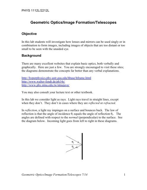
PHYS 1112L/2212L<strong>Geometric</strong> <strong>Optics</strong>/<strong>Image</strong> <strong>Formation</strong>/<strong>Telescopes</strong>ObjectiveIn this lab students will investigate how lenses and mirrors can be used singly or incombination to form images, including images of objects that are too distant or toosmall to be seen with the unaided eye.BackgroundThere are many excellent websites that explain basic optics, both verbally andgraphically. Here are just a few. You are strongly encouraged to visit these sites;the diagrams demonstrate the concepts far better than any verbal explanations.http://hyperphysics.phy-astr.gsu.edu/hbase/hframe.htmlhttp://www.walter-fendt.de/ph14e/http://www.phy.ntnu.edu.tw/ntnujava/You may also consult your lecture text or other textbook.In this lab we consider light as rays. Light rays travel in straight lines, exceptwhen they don’t. They don’t in cases where they are reflected or refracted.In reflection, a light ray impinges on a surface and bounces back. The law ofreflection is that the angle of incidence θ i equals the angle of reflection θ r . Theangles are defined with respect to the normal (perpendicular) to the surface. Seethe diagram below. Incoming light goes from left to right in these diagrams.<strong>Geometric</strong> <strong>Optics</strong>/<strong>Image</strong> <strong>Formation</strong>/<strong>Telescopes</strong> 7/14 1
PHYS 1112L/2212LThe law of reflection applies whether the reflecting surface is straight or curved.For a curved or irregular surface, the normal to the surface is drawn perpendicularto the tangent to the surface at the point of interest.In refraction, light rays pass from one medium to another. Since light travels atdifferent speeds in different media, the rays are bent towards or away from thenormal to the surface between the two media. The index of refraction n for amedium is the ratio of the speed of light in a vacuum c to the speed of light in thatmedium v, that is, n = c/v. The rule for refraction, known as Snell’s law, is thatthe angles of incidence and refraction are related by the following formula:n i sin θ i = n r sin θ rReflection and refraction can be used to bend light rays in interesting ways. Apolished piece of glass, metal, or plastic can serve as a mirror to reflect light rays.A piece of glass or plastic, or a container of liquid, can serve as a lens to refractlight rays. These elements can be used in combination to make useful opticaldevices.A converging lens or mirror takes parallel incident light rays and brings themtogether (makes them converge) to a point called the focal point. The distancebetween the center of the lens and the focal point (or between the surface of themirror and the focal point) is called the focal length. See the diagrams below.<strong>Geometric</strong> <strong>Optics</strong>/<strong>Image</strong> <strong>Formation</strong>/<strong>Telescopes</strong> 7/14 2
PHYS 1112L/2212LA diverging lens or mirror takes parallel incident rays and spreads them apart(makes them diverge) as if they were all coming from a single point (again, calledthe focal point).<strong>Geometric</strong> <strong>Optics</strong>/<strong>Image</strong> <strong>Formation</strong>/<strong>Telescopes</strong> 7/14 3
PHYS 1112L/2212LIn this lab you will verify the law of reflection and Snell’s Law; determine thefocal lengths of converging and diverging lenses; and construct simple opticaldevices using these elements.EquipmentPlane (flat) mirrorsCurved mirrorsConverging lenses (150-mm and 75-mm)Acrylic ray optics set (box with acrylic shapes)Magnetic optical benchComponent holdersScreen (white card)Magnification scaleRay box (light source)LaserVernier caliperReflecting telescopesProcedureCAUTION: some of the lenses we use in this lab are glass. Glass lenses breakeasily. Be very careful with the glass lenses!NOTE: throughout this procedure, make it clear in your ray diagrams which raysare incoming and which are reflected or refracted. You can use different coloredpencils and/or different symbols (such as dotted or dashed lines) to do this.NOTE: Be sure to include all drawings and diagrams in your lab report.Mirrors - ReflectionMeasure Angle of Reflection - Plane Mirror1. Tape the plane mirror securely to the edge of the table so that about half totwo-thirds is above the surface of the table. Lay a piece of paper on the tableagainst it and construct a normal (perpendicular) to the mirror’s surface.2. Set up the ray box (set it to put out one ray) or the laser on the table and shineit on the mirror at an angle of 30° to the normal.<strong>Geometric</strong> <strong>Optics</strong>/<strong>Image</strong> <strong>Formation</strong>/<strong>Telescopes</strong> 7/14 4
PHYS 1112L/2212LFind, draw, and label the reflected ray. Measure and record the angle of reflection.Determine Focal Lengths and Centers of Curvature – Curved Mirrors1. Set up the cylindrical curved mirror (large curved metal object) on a piece ofpaper on the table with the concave side toward the ray box. Outline the mirrorand draw a line representing its principal axis (through the center andperpendicular to the surface).2. Set up the ray box to shine five parallel rays on the mirror. Line up the middleray with the principal axis.3. Determine the focal length as follows:• Find and draw the reflected rays. The point where they converge is thefocal point. Find and label this point.• The focal length is the distance along the principal axis from the surface ofthe mirror to the focal point. Label the focal length on your diagram.Measure and record this value.4. Determine the center of curvature:• Shine the laser at several different points across the curved surface of themirror. Each time, align the laser so that the reflected ray shines right backinto the laser. Mark the rays.<strong>Geometric</strong> <strong>Optics</strong>/<strong>Image</strong> <strong>Formation</strong>/<strong>Telescopes</strong> 7/14 5
PHYS 1112L/2212L• The point where all these rays intersect is the center of curvature (label iton your diagram). The radius of curvature is the distance along theprincipal axis from the surface of the mirror to the center of curvature.Measure and record this value.5. The radius of curvature should be twice the focal length. Calculate this idealvalue. Compare your measured value to the ideal (calculate a percent error for themeasured value).6. Now repeat the entire process with the convex side toward the lasers. Thistime you will need to extend the reflected rays through the mirror (use dashed ordotted lines) to determine the focal length and radius of curvature.Lenses – RefractionDetermine Focal Lengths – Acrylic LensesYou can find the focal lengths of lenses the same way you do mirrors. Repeat thecurved mirror procedures, but use the acrylic double-convex and double-concavelenses from the optics set. With the concave lens, you will have to extend theemerging rays BACKWARDS through the lens (use dashed or dotted lines) todetermine the focal length. Label the focal point and focal length on each diagram.Skip the part about finding the center of curvature; just determine the focal length.Double-Convex Lens<strong>Geometric</strong> <strong>Optics</strong>/<strong>Image</strong> <strong>Formation</strong>/<strong>Telescopes</strong> 7/14 6
PHYS 1112L/2212LDouble-Concave LensDetermine Index of Refraction – Snell’s Law1. Set up the large rectangular block on a piece of paper, largest side down. Drawthe outline of the block on the paper.2. Shine one ray or the laser onto the block at an angle, as shown in the diagrambelow. Draw the path of the ray on the paper.3. Find the ray emerging from the block. Draw its path on the paper. Noteclearly the ray entrance and exit points at the edge of the block.4. Remove the block. Connect the entrance point and the exit point with a dashedor dotted line. This represents the path of the ray through the block.5. Construct the normals (perpendicular lines) to the block’s surface at theentrance and exit points. Measure the angles of incidence and refraction for theentrance point (see the right-hand diagram above).6. Calculate the index of refraction n from Snell’s Law: n i sin θ i = n r sin θ r .(Take the index of refraction of air to equal 1.) Compare it with the stated value,1.5, and calculate a percent error.<strong>Geometric</strong> <strong>Optics</strong>/<strong>Image</strong> <strong>Formation</strong>/<strong>Telescopes</strong> 7/14 7
PHYS 1112L/2212LConstructing Optical DevicesIn these next procedures we will use lenses and sometimes mirrors to constructsimple versions of common optical devices – the astronomical (refracting)telescope, the reflecting telescope, and the compound microscope. First we willneed to find the focal lengths of the lenses.Measure Focal Lengths – Lenses1. Obtain two lenses: one 150-mm double-convex (lens A) and one 75-mmdouble-convex (lens B). Mount lens A on a component holder. You can place itsideways or use Nd magnets as spacers. In either case, be sure it is vertical andthe lens is aligned with the square hole in the holder. Tape or clip the screen(white card) on a component holder, again ensuring that it is vertical. Set the lensand screen on the optical bench so that light will come from the window, throughthe lens, and onto the screen. (Night classes: if it’s too dark outside, focus onsomething across the lab, or down the hall, as far away as possible. Or use the raybox object – the light source with the crossed arrows and circles – at a largedistance from the lens.) See the diagram below.2. Move the screen relative to the lens until a sharp, clear image of the objects(buildings, trees, etc.) across the parking lot is formed on the screen. Is the imageupright (right side up) or inverted (upside down)?3. The focal length of the lens equals the distance between the center of the lensand the screen. Determine the location of the center of the lens to the best of yourability. Measure and record the focal length.4. Replace lens A with lens B and repeat the entire procedure. Record both focallengths f A and f B . Compare your measured values to the stated ones.Construct an Astronomical (refracting) Telescope1. Place lens A and lens B on the bench so that the distance between them equalsthe sum of their focal lengths. See the link below for a diagram of the setup:<strong>Geometric</strong> <strong>Optics</strong>/<strong>Image</strong> <strong>Formation</strong>/<strong>Telescopes</strong> 7/14 8
PHYS 1112L/2212Lhttp://hyperphysics.phy-astr.gsu.edu/hbase/geoopt/teles.html#c12. Turn the bench so that lens A is closer to the window/light. Lens A will be theobjective, the light-gathering element. Lens B will be the eyepiece, the lightfocusingelement.3. Look across the parking lot, or across the lab, at some very distant object.Taking care not to drop the lenses, point the telescope at your very distantobject. Look through the eyepiece and adjust its position until you can see asharp, clear, image of your very distant object. Note whether the image isupright (right side up) or inverted (upside down).4. Point the telescope at the magnification scale (the paper with the largehorizontal black lines). Look through the scope with your left eye, and lookdirectly at the scale with your right eye, all at the same time. (This may takepractice. Switch the two eyes if you need to.) You should see the scale and amagnified version of it juxtaposed.5. One division of the magnified scale will take up the same amount of space asseveral divisions on the directly seen scale. Note and record how manydivisions this is. This number equals the magnification of your telescope.Below is a very simplified version of what it might look like if your telescopehad a magnification of 3.<strong>Geometric</strong> <strong>Optics</strong>/<strong>Image</strong> <strong>Formation</strong>/<strong>Telescopes</strong> 7/14 9
PHYS 1112L/2212L6. Calculate the theoretical value of the magnification using the formula f o /f e (theratio of the focal length of the objective divided by the focal length of theeyepiece). Compare your measured value of the magnification to thistheoretical value (calculate a percent error).Congratulations. You just made a refracting telescope, as Hans Lippershey did in1608.Construct a Compound Microscope1. Set up the ray box (with the crossed arrows and circles) as an object at oneend of the bench.2. Place lens B on the bench about 10 cm from the ray box. Lens B will nowserve as the objective, the light-gathering element.3. Take the screen and move it along the bench, away from lens B, until a sharp,clear image of the object forms on the screen.4. Starting at the screen and moving away from the object and lens B, measure adistance of f A away from the screen. Place lens A at that position. Lens A willnow serve as the eyepiece, the light-focusing element. The idea is to get the imageformed by lens B at the focal point of lens A. See the link and diagram below:http://hyperphysics.phy-astr.gsu.edu/hbase/geoopt/micros.html#c15. Remove the screen and look through the eyepiece at the object. Adjust theeyepiece as necessary.What happens is that a small object is magnified slightly by the objective and thensignificantly by the eyepiece.6. Align your eye so that the object is centered in the image of lens B. Youshould see the scale, marked in millimeters. Count and record how manymillimeters are spanned by the image of lens B. Then measure the actual diameter<strong>Geometric</strong> <strong>Optics</strong>/<strong>Image</strong> <strong>Formation</strong>/<strong>Telescopes</strong> 7/14 10
PHYS 1112L/2212Lof your lens B (in millimeters) with the Vernier caliper. The ratio of the numberseen to the diameter is the magnification of your telescope. Record this number.7. Again being sure not to drop the lenses, look through the eyepiece at somesmall object not too far away (a lab partner’s eye is usually good for a laugh onthis one). See if you can estimate a magnification for this small object.Congratulations. You just made a compound microscope, as Zaccharias Janssen isbelieved to have done in 1595.Construct a Reflecting Telescope (optional)1. Measure the focal length of the mirror first. Mount the round concave mirroron the optical bench to reflect the light from across the parking lot (or acrossthe room if it’s too dark outside). Hold the screen next to the bench (to avoidblocking all the light) and move it closer or farther away to get a sharp, clearimage of the stuff across the parking lot.2. Measure and record the focal length of the mirror, which equals the distancefrom the screen to the surface of the mirror.3. Take away the screen and put a small plane (flat) mirror in its place. Put theplane mirror 6 cm inside the focal length of the curved mirror. Angle it so thatthe light reflected by it is perpendicular to the optics bench. See the followinglink for a diagram of the setup:http://bama.ua.edu/~ddesmet/id/id34c.gif4. Put the screen so it will catch this reflected light, and move it until a sharp,clear image is formed.5. Take away the screen and put lens B in its place. Look through lens B andfocus on some very distant object.6. Point the telescope at the magnification scale (the paper with the largehorizontal black lines), or bring the magnification scale to your telescope.Look through the scope with one eye, and look directly at the scale with theother eye, all at the same time. (This may take practice.) You should see thescale and a magnified version of it juxtaposed. Do the best you can.7. One division of the magnified scale will be the same size as several divisionson the directly seen scale. Note and record how many divisions this is. Thisnumber is the magnification of your telescope.<strong>Geometric</strong> <strong>Optics</strong>/<strong>Image</strong> <strong>Formation</strong>/<strong>Telescopes</strong> 7/14 11
PHYS 1112L/2212L8. Compare your measured magnification with the theoretical value, which isgiven by the same formula as before, f o /f e .Congratulations. You just made a reflecting telescope, as Sir Isaac Newton didaround 1670.A Real Telescope!1. Get out one of the red reflecting telescopes. Point it at the shelves across thelab, or at the scenery out the window. Move the eyepiece to focus the image.2. Ask your instructor for the focal lengths of the mirror and eyepiece. Calculatethe theoretical magnification of the telescope. (magnification = f o /f e )3. Look through the other red telescope (its eyepiece has a different focal length)and repeat the procedure and calculation. Which of the red scopes would bebetter for a large close object like the Moon? Explain.CalculationsFor each device, calculate a percent error for your estimated magnification values.QuestionsWhy did Newton find it necessary to invent a reflecting telescope? Explain.(2212L only) Answer the following questions from the Cioffari manual:Lab 35: Q3, 11, 12 (Q1, 2 are XC) Lab 36: Q7, 9 (Q4, 6 are XC)<strong>Geometric</strong> <strong>Optics</strong>/<strong>Image</strong> <strong>Formation</strong>/<strong>Telescopes</strong> 7/14 12
PHYS 1112L/2212LData Sheet – <strong>Geometric</strong> <strong>Optics</strong>/<strong>Image</strong> <strong>Formation</strong>/<strong>Telescopes</strong>Plane Mirrorangle of incidence_________ angle of reflection __________Concave mirror focal length_________ radius of curvature ___________percent error______________Convex mirror focal length_________ radius of curvature ___________percent error_______________Acrylic double-concave lens focal length___________Acrylic double-convex lens focal length___________Rectangular blockEntrance point index of refraction__________ percent error_______Double-convex lens focal lengths: lens A_________ lens B___________Percent error for A_________ Percent error for B_____________Astronomical (refracting) telescopeMagnification: theoretical ______ estimated _______ % error________Compound MicroscopeMagnification: ______Reflecting telescopeMagnification: theoretical ______ estimated _______ % error________Red telescope #1Mirror focal length f o ___________ eyepiece focal length f e ___________Magnification________________Red telescope #2Mirror focal length f o ___________ eyepiece focal length f e ____________Magnification________________Which red telescope would be more useful for looking at the Moon? Explain.<strong>Geometric</strong> <strong>Optics</strong>/<strong>Image</strong> <strong>Formation</strong>/<strong>Telescopes</strong> 7/14 13