Operating Instructions - Pumpenfabrik Ernst Vogel
Operating Instructions - Pumpenfabrik Ernst Vogel
Operating Instructions - Pumpenfabrik Ernst Vogel

Create successful ePaper yourself
Turn your PDF publications into a flip-book with our unique Google optimized e-Paper software.
<strong>Operating</strong> <strong>Instructions</strong>HV 1.1-HV 1.2Incl. RS 485 - interfaceV 200807A771079212 MANUAL HV1_1-1_2-L-EN ENGLISH
Index1 IMPORTANT SAFETY INSTRUCTIONS ............................................................................................52 SYSTEM DESIGN...........................................................................................................................73 PRESSURE TANK ..........................................................................................................................84 TRANSDUCER ...............................................................................................................................94.1 PRESSURE TRANSMITTER SERIES PA-21 R ..........................................................................................94.2 DIFFERENTIAL PRESSURE TRANSMITTER SERIES PD 39 M .....................................................................105 TECHNICAL DATA - FREQUENCY INVERTER AND GENERAL DATA..............................................115.1 DIMENSIONS ................................................................................................................................126 HYDROVAR MOUNTING .............................................................................................................136.1 MOUNTING THE HYDROVAR ON THE PUMP .......................................................................................136.1.1 Included components...........................................................................................................136.1.2 Mechanical mounting ..........................................................................................................146.1.3 Mounting the thermistor (4) ................................................................................................176.1.4 Mounting of the pressure transducer..................................................................................186.2 ELECTRIC INSTALLATION AND WIRING..................................................................................................196.2.1 Means of protection ............................................................................................................196.2.2 Wiring the Hydrovar to the motor........................................................................................196.2.3 Control.................................................................................................................................226.2.4 Terminals .............................................................................................................................226.3 FRONT PLATE ................................................................................................................................247 OPERATION WITHOUT EXTERNAL PROGRAMMING DEVICE.......................................................258 POSSIBLE INDICATIONS OF THE LED ON THE HYDROVAR..........................................................269 OPERATION IN THE MAIN MENU................................................................................................2710 CONNECTING THE EXTERNAL PROGRAMMING DEVICE TO THE HYDROVAR .............................2811 TYPICAL APPLICATIONS..............................................................................................................2911.1 SETTING SINGLE PUMP CONSTANT PRESSURE .......................................................................................2911.2 SINGLE PUMP - PUMP PROTECTION....................................................................................................3011.3 SINGLE PUMP – SYSTEM CURVE COMPENSATION ..................................................................................3211.4 ENTERING COMPENSATION VALUES ...................................................................................................33MULTIPLE PUMP CONSTANT PRESSURE AND SYSTEM COMPENSATION....................................................................3512 SETTINGS AT THE INVERTERMENU.............................................................................................4013 SETTINGS AT THE SUBMENU-PARAMETER .................................................................................4113.1 PRESSURE CHANGE.........................................................................................................................4113.2 AUTO START .................................................................................................................................4113.3 MODE.........................................................................................................................................4213.4 CONTROL RESPONSE.......................................................................................................................4213.4.1 Dimension unit ...................................................................................................................4213.5 SUBMENU INVERTER .......................................................................................................................4213.5.1 Maximum Frequency...........................................................................................................4213.5.2 Minimum frequency............................................................................................................4313.5.3 Boost ..................................................................................................................................4313.5.4 Operation of the minimum frequency.................................................................................4313.5.5 Delay time for Fmin.............................................................................................................4313.6 SUBMENU CONTROLLER ..................................................................................................................4413.6.1 Window - %........................................................................................................................4413.6.2 Ramp Hysteresis..................................................................................................................443
13.6.3 Fast acceleration time .........................................................................................................4413.6.4 Fast deceleration time.........................................................................................................4413.6.5 Slow acceleration time........................................................................................................4413.6.6 Slow deceleration time .......................................................................................................45RAMP WINDOW......................................................................................................................................4513.6.7 Compensation Frequency....................................................................................................4513.6.8 Lift-Intensity........................................................................................................................4613.7 SUBMENU MULTICONTROLLER ..........................................................................................................4713.7.1 Lift Value ............................................................................................................................4713.7.2 Fall Value ............................................................................................................................4813.7.3 Release – Follow up pump ..................................................................................................4813.7.4 Switch Interval ....................................................................................................................4913.8 SUBMENU RELAY ...........................................................................................................................4913.8.1 Relay Configuration ............................................................................................................4913.8.2 Start frequency of the slave pump......................................................................................4913.8.3 Stop frequency of the slave pump ......................................................................................4913.9 SUBMENU SENSOR.........................................................................................................................5013.9.1 Sensor – Adjust ...................................................................................................................5013.9.2 SensorMax-Adjust...............................................................................................................5013.10 SUBMENU TEST-RUN ......................................................................................................................5013.10.1 Start of manual test run....................................................................................................5013.10.2 Sequence for automatic test run.......................................................................................5113.10.3 Test Run: Frequency .........................................................................................................5113.10.4 Test Run: Boost.................................................................................................................5113.11 SUBMENU ERROR...........................................................................................................................5113.11.1 Conveyor Limit..................................................................................................................5113.11.2 Error Delay........................................................................................................................5113.12 SET PASSWORD .............................................................................................................................5213.13 DEFAULT SETTINGS.........................................................................................................................5213.14 SUBMENU DIAGNOSIS.....................................................................................................................5213.14.1 Pump Runtime ..................................................................................................................5213.14.2 Pump Address...................................................................................................................5213.14.3 Error memory....................................................................................................................5213.14.4 Software Version ..............................................................................................................5313.15 SET PASSWORD .............................................................................................................................5314 CONTROLLER MENU (OF THE PROGRAMMING DEVICE) ............................................................5314.1 CONTROLLER MENU CONFIGURATION .................................................................................................5314.1.1 Automatic connection to the programming device.............................................................5414.1.2 Software Version of the programming device.....................................................................5414.2 SUBMENU ADDRESS........................................................................................................................5414.2.1 Change of pump address....................................................................................................5415 POSSIBLE ERROR MESSAGES......................................................................................................5515.1 LOW WATER.................................................................................................................................5515.2 OVERHEATING – MOTOR .................................................................................................................5515.3 OVERVOLTAGE ..............................................................................................................................5515.4 UNDERVOLTAGE ............................................................................................................................5515.5 OVERLOAD...................................................................................................................................5515.6 OVERHEATING OF THE HEAT SINK.......................................................................................................5615.7 SENSOR FAULT ..............................................................................................................................5615.8 CONVEYOR LIMIT FAULT...................................................................................................................5615.9 ADDITIONAL INTERNAL PROCESSOR ERROR MESSAGES: ...........................................................................5616 MAINTENANCE...........................................................................................................................57Follow the Pump <strong>Operating</strong> and Maintenance <strong>Instructions</strong>We reserv the right to alter specifications4
1 Important safety instructionsRead and follow the operating instructionsand safety instructions carefully beforestarting operations! All modifications must bedone by qualified technicians!In addition to the instructions contained in these operating instructions please payattention to universal safety and accident prevention regulations.The HYDROVAR drive head must be disconnected from the power supply before any workcan be carried out in the electrical or mechanical part of the system.Installation, maintenance and repair work may only be carried out by trained, skilled andqualified personnel.Unauthorised modifications or changes to the system make all guarantees null and void.When in operation the motor can be stopped by remote control, whereby the drive headand the motor remain under voltage. For safety reasons, the unit must be disconnectedfrom the power supply when carrying out work on the machinery as locking out theequipment by switching off the release mechanism or set value cannot prevent accidentalstarting of the motor.When the drive head is connected to power supply, the components of thepower unit as well as certain components of the master control unit are alsoconnected to the power supply.Touching these components seriously endangers life !Before removing the frequency inverter cover the system must bedisconnected from the power supply. After switching off the power supplywait at least 5 minutes before starting work on or in the HYDROVAR drivehead (the capacitors in the intermediate circuit have to be discharged by theinstalled discharge resistors first).Voltages of up to 400 volts are possible (if there are faults it can be higher).All work carried out when the frequency inverter is open may only beperformed by qualified authorised staff.Furthermore, care must be taken not to short circuit the neighbouringcomponents when connecting the external control wires and that opencable ends which are not in use are insulated.5
The HYDROVAR drive head contains electronic safety devices which switch offthe control element in the event of faults, whereby the motor has zero currentbut remains energised and comes to a halt. The motor can also be halted bymechanical blocking. If it is switched off electronically the motor isdisconnected from the mains voltage through the electronics of the frequencyconverter but is not potential-free in the circuit.In addition voltage fluctuations, especially power failures can cause thesystem to switch off itself.Repair of faults can cause the motor to start up again.The system may only be put into operation when it has been earthened. In addition,equipotential bonding of all pipes must be ensured.The operating instructions must be read, understood and followed by the operatingpersonnel. We point out that we accept no liability for damage and operating disorderswhich are the result of non-compliance with the operating instructions.Pleasenote:High voltage tests of the inverter or the motor may damage theelectronic components! Hence bridge before the in- and outgoingterminals L -N -- U- V-W.To avoid incorrect metering by capacitors incorporated in theelectronic part isolate the motor from the Hydrovar Drive head.6
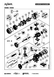
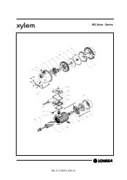
2 System DesignThe following diagrams show typical single pump and multi-pump systems using theHydrovar control unit. Connection can be made directly to a water supply or watercan be drawn from a break tank or well. In the case of break tanks and wells, levelswitches, should be used to shut down the pumps when water is low. In the directconnection, a pressure switch on the suction side should be used.Single pump layout(1) pump with drive head(2) diaphragm tank(3) distribution panel(4) gate valves(5) non return valves(8) incoming pressure switch(9) pressure gauges(14) pressure transmitterMultiple pump Layout7
3 Pressure tankA diaphragm pressure tank is used on the discharge side of the pump or pumps tomaintain pressure in the line when there is no demand. This will keep the pumps fromcontinuing to run. With the Hydrovar control unit, it is not necessary to have a large tankfor supply purposes. In selecting a tank, make sure it can withstand systems pressure. Thetank should have a capacity of more than 10% of the maximum system flow rate l/min ofone pump.Ask of required certificates needed for your country!Precharge the tank to the following:Solldruck / required pressure [bar]Before checking the precharge pressure, take care, that the tank, ispressureless (no water inside).8
4 Transducer4.1 Pressure Transmitter Series PA-21 RThe sensor of this transmitter is a piezoresistive silicon pressure sensor, mountedon a tape (TAP) freely floating in an oil chamber. The pressure is transferred tothe sensor by a separate nickel diaphragm in the oil chamber.SpecificationsRange (FS): 10 bar (other ranges upon request)Max. pressure-P max : 20 barClass of protection : IP 67Output signal:0,5 – 4,5 V DC (ratiometric)Supply: 5 VDC +/- 5 %<strong>Operating</strong> temperature:Storage Temperature:-20...+80°C-40...+100°Cconnections:+ VCC ⇒ brown = supply voltage+ Out ⇒ white = analogue output signalGND ⇒ green = GroundMaterials:Body: steel and brassdiaphragm: nickelPressure Transmitter:Plug:9
4.2 Differential Pressure TransmitterSeries PD 39 MThe sensors of this differential pressure transmitter are two piezoresistive silicon pressuresensors, mounted on a tape (TAP) freely floating in an oil chamber. The pressure istransferred to the sensor by a separate steel diaphragm in the oil chamber.SpecificationsRange(FS): 4 bar differentialOver-pressure- Pmax: 16 bar single-sidedClass of protection : IP 65Output Signal:0,5 – 4,5 V DC (ratiometric)Supply: 5 VDC +/- 10 %Load Resistance:> 5 kΩLinearity::Stability:<strong>Operating</strong> temperature:Storage Temperature:±0.20 % FS; max. ±0.5% FS±0.1 % FS; max. ±0.2% FS-10...+80°C-40...+80°CMaterial: Body and diaphragm: 1.4435 Stainless steelScrew joint and cover: Steel electroplated for Emetorpipe d=8mmPlug: mPm 193P -P +Incl. 2m cable:Out (white)+ Vcc (brown)GND (green)Screen10
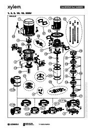
5 Technical Data - Frequency Inverter And General DataHYDROVAR Hydrovar output tothe MotorSupply Voltage (Uin) Prefusemin.Type RatedoutputVoltage Max.currentMains frequency48-62 HzHV 1.1 1,1 kW 3x 230 V 4,8 A 1x 220-240 V±15% 10 AmpereHV 1.15 1,5 kW 3x 230V 7,0 A 1x 220-240 V ±15% 10 AmpereHV 1.2 2,2 kW 3x 230V 10,0 A 1x 220-240 V ±15% 16 AmpereOutput voltage:3x 0...Uin VAC / 0-70 Hz(depends on the input voltage)Min. frequency:0 – max. frequencyElectrical efficiency: > 95%Protection against: Short circuit, over- and undervoltage, overheating of theelectronics (overload) and additional external protective functionsvia PTC (motor temperature) and low water switch.A mains filter is fitted to ensure interference immunity.The HV Series frequency converter complies with the general EMC provisions and hasbeen tested according to the following standards:• Disturbance voltage: EN 55011• EMC – Immunity: EN 61000-4-3 and ENV 50204• Electrostatic discharge: EN 61000-4-2Ambient temperature: 5° C ... + 40°CStorage temperature: -25° C ... + 55° C(+70°C during max. 24 hours.)Humidity:rH max. 50% at 40°C, unlimitedrH max. 90% at 20°C, max. 30 days per yearCondensation not permitted !Air pollution:Altitude::Class of protection :The air may contain dry dust as found in workshops wherethere is no excessive quantity of dust due to machines.Excessive amounts of dust, acids, corrosive gases, salts etc.are not permittedmax. 1000m above sea levelAt higher altitudes the max. available power has to bereduced. Please ask the manufacturer for further details.IP5511
Variant A:6.1.3 Mounting the thermistor (4)motorthermistorterminal blockrubber gasketcover of theconduit boxVariant B:Thermistor1. Open the cover of the conduit box and remove also the terminal block inside.2. Fix the thermistor (Variant A or B)3. Electrical connection of the motor cables see chapter 7.3.17
6.1.4 Mounting of the pressure transducerIn the delivery of the pressure transducer there are included:(1) pressure transducer(2) gasket(3) reducer 3 / 8 “ – ¼“(4) brass gasket(1)(3)(2)(4)1. The transducer has an mechanical connection of G ¼”. If it is necessary put the reducer(3/8” – 1/4”) into the pump or pipe by using included gaskets.2. Electrical connection to the Hydrovar see chapter (6.2.4)18
6.2 Electric installation and wiringNote:All installations and maintenance MUST be performed bytrained and qualified personal with proper tools!!Warning:In case of a failure, disconnect and lockout electrical power and waitfive minutes for capacitor discharge before servicing the Hydrovar.Otherwise it can cause shock, burns, or death.6.2.1 Means of protectionAsk your power supply company which means of protection are required.Applicable:AC and DC current-operated circuit breaker (FI), TN systems, protectivecircuits.When using a FI protection switch, make sure that it also releases in the event ofa DC fault, use for each Hydrovar a separate FI-switch!6.2.2 Wiring the Hydrovar to the motorRemove the 3 screws holding the top of the Hydrovar. Carefully lift the top, loose the earthscrew and put the Hydrovar cover aside.Now you can see the 2 main parts(1) control card with all terminals for the control signals and the RS485interface(2) main card with all power components and terminals for power supplyand motor19
6.2.2.1 Main part overviewHV1.1:control card (1)main supplyconnectionsMotor connectionsCableintroductionfor motor cable (atleast 11,5mm)main board (2)Cable gland (forpower supply 5-10mm)HV1.15, 1.2:Cableintroduction for controlcable (at least 5mm)control card (1)main board (2)main supply connectionsmotor connectionscable introduction forcontrol cable6.2.2.2 Connecting the power cables20
a) motor cable:Locate the motor connections, labeled U, V, W inside the Hydrovar. Connect wires to theterminals and rout the cable through the cable gland.You must take a motor cable at least Ø 11.5mm if you want protection IP55. (only HV1.1)The earth-wire of the cable has to be fixed with the screws with the earth-symbol to thecooling body of the Hydrovar.Connections in the conduit boxThe connection of the motor cable depends on the type of the motor and can be done instar or delta connection:(you have to use the connection for a motor voltage of 3x230V shown on the motor label)Star-connectionDelta-connectionb) supply cableThe main power cable is connected to the terminals labelled L1, N for the 230 VAC, singlephase input (shown in the diagram 6.2.2.1).21
6.2.3 ControlBy using the HYDROVAR drive head for constant pressure control, together witha pressure or differential pressure transmitter, or, if required, according toexternal manual control by reference of 0,5-4,5VDC, this external signal has tobe connected to the terminals X2/1, X2/2 and X2/3 of the control terminals.terminals of theRS485 interfaceHV1.1control terminalsHV1.15, 1.26.2.4 TerminalsAll externally used cables have to be shielded. Do not connect the mass of the electroniccomponents to other higher potentials.All electronic ground and GND of the RS 485-interface are internally connected.For external off/on and low water, switch contacts suitable for
Control-Terminals:ThermistorExternal release Ri 10kOhm, 5VDC (use goldplated contact)Power supply for external control 5VDC0,5-4,5 VDCGround (not earthened)23
6.3 Front plateHV 1.1-1.2:indication LEDpush buttons24
7 Operation without external programming deviceAttn:Before you start the system, the pump must be filled and all wiring and pipinghave to be done!The Hydrovar is delivered with these settings as standard!♦ Change Pressure: enabled♦ Auto Start: enabledOther possibilities to use the push buttons of the Hydrovar:The Pump could beSTARTED with the button (if Autostart is disabled, the pump can be started bypressing the button and then the button at the first startup or after apower supply failure) orSTOPPED with the button.Both buttons are on the front plate of the Hydrovar• Change pressure without programming device:To change the pressure without the external programming device you have tofollow:1. Start the pump with the push button on the front plate of the Hydrovar2. Then press the and buttons together for longer than 3 sec.3. The colour of the LED changes to orange4. Now you can change the pressure with the and buttons.The only way to check the set pressure is given by a pressure gauge.5. If there is no action for more than 5 sec., the HYDROVAR returns to normaloperation automatically, and the new required pressure is saved.25
8 Possible indications of the LED on the HYDROVAR.) Green shining ⇒ Motor stopped(via external stop with terminals X2/4; X2/5or the unit is stopped with the button on the frontplate).) Green slow flashing ⇒ Inverter is active, but the motor has stopped.) Green fast flashing ⇒ Motor runs.) Orange shining ⇒ required pressure can be changed without theprogramming device with the buttons and ,or the external programming device is connected and thepump is stopped with the button on the Hydrovar orwith the external release input (terminals X2/4 and X2/5)..) Orange slow flashing ⇒connected remote control and the inverter is released,but the pump is not running (because of the requiredpressure is reached)..) Orange fast flashing ⇒connected external programming device and the pumpisrunning..) Red shining ⇒ error signalling (type of the Error is shown on thedisplay of the external programming device).) Red flashing ⇒ signalling of a fatal error (HYDROVAR has to be cutfrom the power supply!)26
9 Operation in the main menuMenu overview27
General for working with the external programming device:With and you can select the different parameters in the menu.To enter a submenu, press the button. To leave the submenu, you have to pressthe buttons or for longer than 3 sec.With or you can change the parameters.Each change in the settings is saved after leaving this parameter with the buttons or .When you have changed a parameter and you leave it, the LCD shows you thefollowing messageSAVEPARAMETERfor about 2 sec.10 Connecting the external programming device to the HYDROVARAfter connection of the HYDROVAR – head to the power supply and plug in of theexternal programming device, there can be shown two different messages:1. If the AUTOCONNECTION (14.1.1) is disabled (standard) you reach:Address 01LostThis message is shown, when the Remote Control isnew connectedAt this time the Hydrovar searches for an available addressIf address 01 is available, the display changes toAddress 01DetectedThe actual pump-address is shownStatusinformations by systems with activated Multicontroller:P1: MasterpumpP2: SlavepumpP3: SlavepumpP4: SlavepumpP.: Follownumber is not usefulHold: pump stops through the pressure transmitterRun: pump runsStop: pump stops through the leadpumpDisabled: pump stops through the stopbutton or the terminal blockError: pump stops through an error Follow pump stopped Regulator from the follow pump is releasePump don’t work at the follow pump28
If the actual pump address 01 is not available the display does not change and youwill see againAddress 01LostThen you could change the address with and and confirm the selected address with .Press on the controller and you enter the INVERTERMENU (see chapter 12)2. If the AUTOCONNECTION (14.1.1) is enabled, following message is shown:SCANCONNECTIONThis message is shown during the connecting, whenAUTOCONNECTING (chapter 14.1.1) is enabledIn this time the Hydrovar searches for the given or entered address!Then the display changes to the 1 st displayPRESS X.X barSPEED X.X HzThe actual input value [bar] and the actualoutput frequency [Hz] are displayed.11 Typical applications11.1 Setting Single Pump Constant PressureAt the first startup, “Change Pressure” and “Autostart” of the external programming unitare enabled. After connecting, on the display of the programming unit there is shownScanConnectionand scanning a valid pump address.This message is shown when the externalprogramming device is set up to the HydrovarAfter a few seconds, the display changes automatically to the 1 st displayPress x.x barSpeed x.x HzPress on the controller to change toThis window shows the actual values of theHydrovar (a required pressure of 3,5 bar ispreviously set)Pressurexx.x barTo select required pressure use thebuttons and .After changing of the value, you have to confirm with the -button. Then you will getthe message “SAVE PARAMETER” for a short time, when the new setting is saved!After changing of the value, you have to confirm with the -button.Then press on the controller to change back to the 1 st displayPress x.x barSpeed x.x Hz29
11.2 Single Pump - Pump Protection30
Note:Low/no suction depends on the installation of a suction line pressure switch, or float switchfor a tank. This is connected to the Hydrovar as described earlier in the Electrical Installationsection (see chapter 6.2).The cut off setting for this switch should be the maximum NPSH required by the pump.To set run out protection:Note:Run out protection is available for one pump systems and multiple pump systems with acommon suction pipe. In multiple pump systems with separate suction pipes, you can notavoid dry running by measuring the system pressure, because the pressure is producedfrom another pump in the system.From the 1 st display, press the button twice, until youreachThen press the button and the display will change toSUBMENUPARAMETERPASSWORD0000Password:The Password protection prevents untrained personal from accidentally changing thebase settingPress the button until you reach the number 0066Press the button repeatedly until you reachPASSWORD0066SUBMENUERRORPress the button to enter the submenu and change toCONVEYOR LIMIT0,0 barCONVEYOR LIMIT“0.0 bar” means disabled conveyor limit.An adjusted value >0 has to be reached till the programmed “ERROR DELAY”-time.Doesn’t this value be reached the failure “CONVEYOR CONTROL ERROR” will beindicated and the pump stops.By pressing the and button, enter the pressure setting CONVEYOR LIMIT(bar) at which you want the pump to shutoff.0 barTypically a setting of about 1 bar less than the standard pressure setting would be enteredAfter changing of the value, you have to confirm with the button.Then you will get the message “SAVE PARAMETER” for a short time, when the new settingis saved!Press the button to change to31ERROR DELAY10 s
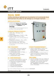
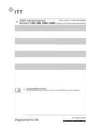
ERROR DELAY:Adjustable between 0...100 sec.Delayed switch-off in the event of low water, terminal X2/6-X2/7) and also for the conveyorlimit ( see chapter 13.11.1).By pressing the and button, you will be entering theERROR DELAYamount of time (sec) that the pump will run at the10 sprogrammed conveyor limit before it automatically shuts off.After changing of the value, you have to confirm with the button. Then you will get themessage “SAVE PARAMETER” for a short time, when the new setting is saved!Hold the button down for 3 seconds and you will bereturned to:Hold the button down again for 3 seconds to return tothe 1 st displaySUBMENUERRORPRESSURE x.x barSPEED xx Hz11.3 Single Pump – System Curve CompensationThe Hydrovar can automatically compensatefor system friction losses due to increasedflow. Tables are available in most pumpcatalogues indication the amount of frictionloss that can be expected in various sizes ofpumps at different flow rates. Use thesetables to determine the friction loss for thepipe size you are using at maximum flowrate.This Diagram shows a typical system curve. The system pressure set point is shown atshutoff and pressure increase is shown for increasing flow.Calculate the pressure required to overcome friction loss at maximum flow.32
11.4 Entering Compensation Values33
<strong>Instructions</strong>:From the 1 st display, press the button twice, until youreachThen press the button and the display will change toSUBMENUPARAMETERPASSWORD0000Password:The Password protection prevents untrained personal from accidentally changing thebase settingPress the button until you reach the number 0066Press the button repeatedly until you reachPress the button to enter the submenu and change toPASSWORD0066SUBMENUCONTROLLERWINDOW5,0 %Now press the button until you reach the parameter “LIFTFREQUENCY”LIFT FREQUENCY30 HzLIFT FREQUENCY:This indicates the frequency at which the increase of the set pressure should begin.It should be the speed at which the pump works at the set pressure and at delivery rate of0 m³/h. On a 50 Hz system, there is virtually no flow below about 30 Hz, on a 60 Hzsystem about 40Hz.Press the and button until you reach desired frequency. LIFT FREQUENCY30 HzAfter changing of the value, you have to confirm with the button.Then you will get the message “SAVE PARAMETER” for a short time, when the new settingis saved!Now press the button to change toLIFT INTENSITY0,0 barLIFT INTENSITY:This value states, how much the required value should be continually increased, till themaximum speed (maximum volume) is reached. Further description, see chapter 13.6.8.Press the and button until you reach desired valueLIFT INTENSITY0,0 barAfter changing of the value, you have to confirm with the button.Then you will get the message “SAVE PARAMETER” for a short time, when the new settingis saved!Hold the button down for 3 seconds to return to:34SUBMENUCONTROLLER
11.5 Multiple pump constant pressure and system compensation35
When two, three or four Hydrovar speed controlled pumps are connected together in asystem via the RS485-interface, they can be programmed to work together to maintainsystem pressure up to the maximum flow rate of all the pumps combined.As the first pump reaches its maximum speed and flow, the second pump willautomatically turn on (and so on). In addition, the sequence of the pump that will run first(lead pump) can be automatically varied to reduce premature wear on any one pump in thesystem.<strong>Instructions</strong>:!! Refer to chapter 11.1 (setting single pump constant pressure).Follow these instructions for setting the required pressure and then continue with thefollowing steps.From the 1 st display, press the button twice, until youreachThen press the button and the display will change toSUBMENUPARAMETERPASSWORD0000Password:The Password protection prevents untrained personal from accidentally changing thebase settingPress the button until you reach the number 0066Press the button repeatedly until you reachPress the button to enter the submenu and change toPASSWORD0066SUBMENUMULTICONTROLLERACTUAL VALUE INCREASE0.15 barACTUAL PRESSURE INCREASE (= Lift value):This value, together with the fall value (ACTUAL VALUE DECREASE) determines the increaseof the required value after starting of the following pumps (see attached applicationexample on next page)36
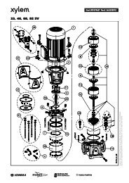
Generally a slight pressure drop is allowed on the first pump before the next is started. Thisallows for brief systems fluctuations without pump cycling. Once thenext pump starts, however, you will want the system to resume its normal setpressure.To do this, enter the amount of pressure dropyou will allow before the next pump starts(=value of parameter ACTUAL VALUEDECREASE). The diagram shows the pressuredrop and increase.For example, if the pressure drop allow 0,35 bar before the next pump starts, andthe increased pressure needed to compensate for system losses is 0,2 bar, you wouldenter 0,35 + 0,20 = 0,55 bar (= calculated value of the parameter ACTUAL VALUEINCREASE) to compensate for both system pressure drop and compensationrequirements.Application example:1) Pump 1 reaches the speed of ENABLE SEQ: CONTROL2) Pressure falls and reaches the start-value of the 2 nd pump(= REQUIRED VALUE – ACTUAL VALUE DECREASE)3) Pump 2 is switched on automatically4) The required value is calculated new, after the start of the 2 nd pump in thefollowing way!New required value = REQUIRED VALUE – ACTUAL VALUE DECREASE + ACTUALVALUE INCREASEGenerally:k ... Number of active pumps (k >1)P = P set + (k-1)*[lift value – fall value]To increase the pressure even more tocompensate for system loss at higher flows,enter the total of the system drop allowedbefore next pump starts and the increasedpressure (ACTUAL VALUE INCREASE) desired.• Lift value = Fall value ⇒ Pressure constant when pumps switch on• Lift value > Fall value ⇒ Pressure rises when lag-pump switches on• Lift value < Fall value ⇒ Pressure falls when lag-pump switches onNote:This value is cumulative. An extra 0,2 bar will be added to the total system pressure witheach additional pump which turns on. For example, if the initial system pressure was 3,5bar, pump two would create 3,7 bar, pump three would create 3,9 bar, and pump fourwould create 4,1 bar system pressure.37
Enter the required value by pressing the and buttonACTUAL VALUE INCREASE0,15 barAfter changing of the value, you have to confirm with the button.Then you will get the message “SAVE PARAMETER” for a short time, when the new settingis saved!Press the button to change toACTUAL VALUE DECREASE0,15 barACTUAL PRESSURE DECREASE (= Fall value):This value determines amount of pressure drop you will allow before the next pump starts.(see application example on previous page)Enter the required value by pressing the and buttonACTUAL VALUE DECREASE0,15 barAfter changing of the value, you have to confirm with the button.Then you will get the message “SAVE PARAMETER” for a short time, when the new settingis saved!Press the button to change toENABLE SEQ. CONTROL48 HzENABLE SEQUENCE CONTROL:The follow-up pump only starts, when the start-value is reached (see chapter 13.7.2) andthe lead pump has reached the programmed release-frequency. (Adjustable from 0.0 Hz to70 Hz). Normally this start frequency is set 1 to 2Hz lower than the MAX. FREQUENCY (seechapter 13.5.1)If you don’t want to start a following pump this value has to be set higher than the MAX.FREQUENCY. (see application example on previous page)Enter the required value by pressing the and buttonENABLE SEQ. CONTROL49 HzAfter changing of the value, you have to confirm with the button.Then you will get the message “SAVE PARAMETER” for a short time, when the new settingis saved!Press the button to change toSWITCH INTERVAL24 HOURSSWITCH INTERVALThis time determines the interval of the changeover of the master pump in order toachieve even operating hours of all pumps in the system. Adjustable between 0 and 250hoursEnter the required value by pressing the and buttonSWITCH INTERVAL24 HOURS38
After changing of the value, you have to confirm with the button.Then you will get the message “SAVE PARAMETER” for a short time, when the new settingis saved!Use the settings of this submenu (lift value, fall value, enable sequence control andswitch interval) for each pump in the Hydrovar systemHold the button down for 3 seconds to return to:Hold the button down again for 3 seconds to return tothe 1 st displaySUBMENUCONTROLLERPRESSURE x.x barSPEED xx HzIf you set the addresses in a multiple pump system the first time, connect only theHydrovar unit where you want to set the address to power supply otherwise allHydrovars in the system connected over the RS485-interface will change theiraddress, tooIn the following section you will give the pump an address number. Generally, the firstprogrammed pump will be number 1, the second will be number 2, and so on. Thepurpose of this is to help the Hydrovar sequence the start and stop activity of the pumps inthe system including the selection of the lead and lag pumps.From the 1 st display, hold the button for longer than 3Address 01sec. to get the display, where the actual address is showDetectedorWhen there is no active address, there is shown Address 01L O S TThen press the button twice to change toPress the button to enter the submenu and change toSubmenuAddressAddress Change00 --> 00 *Addresses from 01 to 04 and also 00 can be set in this parameter. To change the addressit is not necessary to cut the interface connection to other HYDROVARS.On the left side there is shown the address of the HYDROVAR, which you are actuallyspeaking (select the address by using the buttons or ). On the right side, then youcan give the HYDROVAR a new address also with the buttons and . You only cangive an address, which is not used in the pump group!To change between left and right side, press button or . The star shows the actualused side.To save the new selected address press both buttons ( and ) together for 2 sec. If itwas successfully you will see the same address on both sides.39
Example:To change the Hydrovar with address 01 to address 04:press the button to change the * to the left sideSelect the address of the Hydrovar, you want to change theaddress with the and buttonpress the button to change the * to the right sideSelect the address you want to give this Hydrovar with the and buttonAddress Change00* --> 00Address Change01* --> 00Address Change01 --> 00*Address Change01 --> 04*To confirm and save the new selected address press both buttons (and ) togetherfor 2 sec. If it was successfully you will see the same address on both sides.The definition of the address you have to do for each pump in the system.Address Change04 --> 04*Hold the button down for 3 seconds to return to:Hold the button down again for 3 seconds to return tothe 1 st displaySUBMENUAddressPRESSURE x.x barSPEED xx Hz12 Settings at the Invertermenu1 st display PRESS X.X barSPEED X.X HzThe actual input value [bar] and the actualoutput frequency [Hz] are displayed.Press on the controller to change toPRESSUREXX.X barThere you can set required pressurewith the buttons and Press on the controller to change toSUBMENUPARAMETERTo enter the submenu “Parameter”,press buttonPress on the controller to change to 1 st display40
13 Settings at the Submenu-ParameterImportant: Before entering the secondary menu these instructionsmust be read carefully to prevent incorrect settings which willcause malfunction.After entering the SUBMENU PARAMETER, the display... will change toSet Password 0066 by pressing and PASSWORD0000PASSWORD0066Note: The password must be entered at each entryConfirm by pressing and the firstparameter of the sub menu is shownChange PressureEnabled13.1 Pressure changeChange PressureEnabledYou can decide between (Enabled) or (Disabled)If the pressure setting is enabled, you can change the required pressure on theHydrovarhead with decrease and increase (see chapter 7) without an externalprogramming device.Press on the controller to change to13.2 Auto startAuto Start You can select between Disabled and EnabledEnabledAutostart Enabled means, that the pump starts again automatically after aninterruption of the power supply (power failure).If Autostart Disabled is set, the pump has to be restarted manually after a powerfailure, by pressing and .Press on the controller to change to41
13.3 ModeModeControllerSelect with buttons and between:Multicontroller ⇒ sequence control for max. 4 pumpsController ⇒ pressure control for a single pump If only one HYDROVAR-pump is inoperation, set Controller.If more than one HYDROVAR-pumps are working together via the RS485-interface, theMulticontroller must be selected.Actuator ⇒ external frequency setting. The application Actuator is only used, if youhave an external controller and the HYDROVAR works like a standard frequencyconverter (external frequency signal 0,5-4,5VDC to the terminals X2/1 and X2/2).Press on the controller to change to13.4 Control ResponseRegulation ModeNormalNormal: Speed is increased with falling actual valueSignals. (e.g.: Control at constant output pressure).Inverse: Speed is reduced with falling actual valuesignal, (e.g.: Control of constant suction pressure or atconstant level before the pump).Press on the controller to change to13.4.1 Dimension unitDimension unitBarHere you could choose your favourite unit (withbuttons and ) Bar, psi or % for the 1 st display.Press on the controller to change to13.5 Submenu InverterSubmenuInverterTo enter this menu you have to press the key, toleave the menu, press the key longer than 3 sec.Press on the controller to change to13.5.1 Maximum FrequencyMax. Frequency50.0 HzPossible setting between min. 40 and max. 70 Hz.Attention: Settings higher than 50 Hz may overload themotor!Settings of 10% above nominal frequency cause 33%more power consumption!42
Press on the controller to change to13.5.2 Minimum frequencyMin. Frequency0.0 HzHere you can set the minimum frequency.Attention!: If there is set F>Fmin in the parameterCONFIG FMIN (see chapter 13.5.4) the pump will not stop in the normal mode. It willkeep running with the set minimum frequency.!! Possibility of overheating of the pump !!Press on the controller to change to13.5.3 BoostB O O S T The stated value determines the course of the5.0 %U/f-curve.Setting of the motor starting voltage in % of rated voltage.Settings of 0...25% of maximum output voltage are possible. However, care should betaken that settings are kept as low as possible so that the motor does not becomethermally overloaded.Press on the controller to change to13.5.4 Operation of the minimum frequencyConfig. Fmin If you have selected „F->0“ the frequency will goF ⇒ Fmin down to the selected minimum frequency (13.5.2).Then the inverter will run for the selected time(13.5.5)and after this time the Hydrovarwill stop automatically.With the selection is „F->F min “ you can not run the pump below the set minimumfrequency. In the controller, actuator and multicontroller mode the pump will never runbelow the set minimum frequency (the pump will only stop with the external on/offterminalsor in case of a failure).Press on the controller to change to13.5.5 Delay time for FminFmin Time0 sAfter running the pump for this selected time atminimum frequency, the pump will stop, if parameterCONFIG Fmin (see chapter 13.5.4) it set to F ⇒ 0 Adjustable between 0 and 100s.To leave the submenu press the key longer than 3 sec.!43
13.6 Submenu ControllerSubmenuControllerTo enter this menu you have to press the key, toleave the menu, press the key longer than 3 sec.13.6.1 Window - %WindowThis value indicates the max. variation of the outgoing5 %pressure (ref. Ramp window in chapter 13.6.6).Possible setting: between 0% - 100% of required pressure.Press on the controller to change to13.6.2 Ramp HysteresisHysteresis80%Level, where the fast ramp changes to the slowramp within the window.Possible setting: between 0%..100% of the windowPress on the controller to change to13.6.3 Fast acceleration timeTime setting at Ramp 1, 2, 3, or 4 will influence the control of the pumpand SHOULD NOT BE CHANGED at normal operation. Possible setting foreach ramp 0,05 - 1000 sec.Accel. High Excessively fast running up time may overload the4 Secinverter.Excessively slow running up time may cause a break down of the outgoing pressure.Press on the controller to change to13.6.4 Fast deceleration timeDecel. High Excessively fast running down time tends to cause4 Secoscillation or hunting or can cause an error(OVERVOLTAGE) during pump down of the pump.Excessively slow running down time tends to generate over pressure.Press on the controller to change to13.6.5 Slow acceleration time44
Accel. Low70 SecPress on the controller to change toA too slow running up time during variation ofdemand the outgoing pressure may break.A too fast running up time may lead to overoscillation and /or overload of the inverter.13.6.6 Slow deceleration timeDecel. Low70 SecA too fast setting leads to oscillationA too slow setting delays the switching off toomuch and may generate over pressure.Ramp WindowPress on the controller to change to13.6.7 Compensation FrequencyControl according to a system curve (increase of the set pressure depending onthe delivery rate or speed).LIFT FREQUENCY Adjustable between 6 Hz and the set MAXIMUM30.0 HzFREQUENCY, this setting states at which frequencythe set pressure should be increased. That is the speed at which the pump works at the setpressure and at delivery rate 0.Press on the controller to change to45
13.6.8 Lift-IntensityLIFT – INTENS. Adjustable from 0 to 100% of the range of the used0.0 barpressure transmitter.This value states how much the required value should be continually increased, till themaximum speed (maximum volume) is reached.46
Figure: Lift-IntensityTo leave the submenu press the key longer than 3 sec.!13.7 Submenu MulticontrollerSubmenuMulticontrollerTo enter this menu you have to press the key, toleave the menu, press the key longer than 3 sec.13.7.1 Lift ValueACTU. VALUE INC.0.15 BARAdjustable between 0 and 2,5 bar.This value, together with the fall value determines the47
increase of the required value after starting of the following pumps (see attachedapplication example in chapter 13.7.2)Press on the controller to change to13.7.2 Fall ValueFor scaling the required value for 1 to 4 pumpsActu. Value Dec. Adjustable between 0 and 2,5 bar.0.15 barThis value determines the start value of the 2 nd and theother following pumps. (Start-Value = REQUIRED VALUE – ACT. VALUE DEC.)Application example:1) Pump 1 reaches f max (maximum speed )2) Pressure falls and reaches the start-value of the 2 nd pump(= REQUIRED VALUE – ACTU. VALUE DEC.)3) Pump 2 is switched on automatically4) The required value is calculated new, after the start of the 2 nd pump in thefollowing way!New required value = REQUIRED VALUE – ACTU. VALUE DEC. + ACU. VALUE INC.Generally:k ... Number of active pumps (k >1)P = P set + (k-1)*[lift value – fall value]• Lift value = Fall value ⇒ Pressure constant when pumps switch on• Lift value > Fall value ⇒ Pressure rises when lag-pump switches on• Lift value < Fall value ⇒ Pressure falls when lag-pump switches onPress on the controller to change to13.7.3 Release – Follow up pumpEnable Seq. Ctl.48.0 HzThe follow-up pump only starts, when the startvalueis reached (see chapter 13.7.2) and the lead48
pump has reached the programmed release-frequency. (Adjustable from 0.0 Hz to70 Hz). If you don’t want to start a following pump this value has to be set higherthan the MAX. FREQUENCY (see chapter 13.5.1)Press on the controller to change to13.7.4 Switch IntervalSwitch Interval24 hoursFor changing the master pump and follow-uppump in order to achieve even operating hours ofthe pumps. Adjustable between 0 and 250 hoursTo leave the submenu press the key longer than 3 sec.!13.8 Submenu RelaySubmenuRelayTo enter this menu you have to press the key, toleave the menu, press the key longer than 3 sec.13.8.1 Relay ConfigurationRelay Configu.Simple Multicnt.Possible selections with buttons and :Simple Multicnt. ⇒ allows to start a following(simple multi- constant speed pump.controller) (see chapter 13.8.2 / 13.8.3.)Run Signalling ⇒ Run indication over the relayError Signalling ⇒ fault indication over the relayAttn:Max. contact load 500mA / 125VPress on the controller to change to13.8.2 Start frequency of the slave pumpSlave-On Limit Here you can set the frequency of the speed50,0 Hzcontrolled HYDROVAR-pump, when the full speedslave pump should start, if “simple multicontroller” is set in the parameter Relayconfiguration (see capter 13.8.1). In this case, the slave pump runs with full speed andthe HYDROVAR-pump controls the additional demand.Press on the controller to change to13.8.3 Stop frequency of the slave pumpSlave-Off LimitHere you can set the frequency of the speed49
30.0 Hz controlled HYDROVAR-pump, where the full speedslave pump should stop, if “simple multicontroller” is set in the parameter Relayconfiguration (see capter 13.8.1).To leave the submenu press the key longer than 3 sec.!13.9 Submenu SensorSubmenuSensorTo enter this menu you have to press the key, toleave the menu, press the key longer than 3 sec.13.9.1 Sensor – AdjustSENSOR_ADJUST ?Out of rangeZero adjustment of the transmitterDepressurise the system and press keys + simultaneously. After adjustment "adjusted" appears on the display. If “out of range” isshown on the display, no adjustment is possible (e.g. when pressure is in thesystem....)Press on the controller to change to13.9.2 SensorMax-AdjustSENSORMAX-ADJUST The analogue input (terminal X2/2) is prepared for a0,5 – 4,5 V transmitter signal of 0,5 – 4,5VDC.When there is used a transmitter with another signal range, you can also choose aninput signal of 0,5 – 2,5VDC ( for example a 4-20mA-transmitter with an external loadresistor of 125 ohm/0,25W) with the buttons + .To leave the submenu press the key longer than 3 sec.!13.10 Submenu Test-RunSubmenuTestrunTo enter this menu you have to press the key, toleave the menu, press the key longer than 3 sec.13.10.1 Start of manual test runStart Test Run By simultaneously pressing + a test run will be + released even if the test cycle is not set.After starting this test run, the pump will speed up with the fasten ramp 1 to the in theparameter 13.10.3 setted speed and then will ramp down with the fasten ramp 2.50
Press on the controller to change to13.10.2 Sequence for automatic test runTime Test Run Adjustable between 1...100 hours.100 hThe test run starts the pump at the set time afterthe last stop for 20 seconds with the in parameter 13.10.3 set speed.Deactivating test run: Set 0 hours, by using and .Repeating the test run: Select test run and set the desired hours using the key .Press on the controller to change to13.10.3 Test Run: FrequencyTest Frequency30.0 HzFrequency for manual and automatic test run.Can be set from 0 Hz up to 70 Hz.Press on the controller to change to13.10.4 Test Run: BoostBOOST Test Run10.0 %.Start voltage in % of rated voltage in order to ensurethat the motor starts safely. Adjustable between 0%and 25%To leave the submenu press the key longer than 3 sec.!13.11 Submenu ErrorSubmenuErrorTo enter this menu you have to press the key, toleave the menu, press the key longer than 3 sec.13.11.1 Conveyor LimitConveyor Limit Disabled or adjustable between 0 and 10 bar of the0.0 baranalogue input signal range.“0.0 bar” means disabled conveyor limit.An adjusted value >0 has to be reached till the programmed “ERROR DELAY”-time.Doesn’t this value be reached the failure “ERROR WATER” will be indicated and thepump stops.Press on the controller to change to13.11.2 Error Delay51
Error Delay Adjustable between 0...100 sec.10 Sec.Delayed switch-off in the event of low water,(Terminal X2/6-X2/7) and also for the conveyor limit ( see chapter 13.11.1).To leave the submenu press the key for 3 sec.!13.12 Set PasswordSet Password0066The pre-set password can be changed if necessarywith the and keys.Press on the controller to change to13.13 Default SettingsDefault + To load DEFAULT – PARAMETER, press buttons + together, till the timer is run down.Press on the controller to change to13.14 Submenu DiagnosisSubmenuDiagnosisTo enter this menu you have to press the key, toleave the menu, press the key longer than 3 sec.13.14.1 Pump RuntimePump Runtime0000 Std.Shows the running hours of the pump.Press on the controller to change to13.14.2 Pump AddressPump-Address1This window shows the adjustment of the pumpaddress (only read).Press on the controller to change to13.14.3 Error memoryThe last three error messages are always stored in an internal memory. Theerror signals can not be deleted!52
Last Error........................2 nd Error........................3 rd Error........................Shows the last error:Shows the Error before the last error:Shows the Error before Error 2Press on the controller to change to13.14.4 Software VersionSoftwareCP – VOG: 004In this parameter, there is shown the used softwareversion of the HYDROVAR.To leave the submenu press the key for 3 sec.!13.15 Set PasswordPasswordO.K.Here the set or changed password must beconfirmed.14 Controller menu (of the programming device)To reach the controller menu, you have to press on the controller for longer than 3 sec.,when the1 st display PRESS X.X barSPEED X.X HzThe actual input value [bar] and the actual outputfrequency [Hz] are displayed.is shown. Then the display will change toAddress 01DetectedThe actual pump-address is shownThen press on the controller to change to14.1 Controller menu ConfigurationSubmenuConfigurationTo enter this menu you have to press the key, toleave the menu, press the key longer than 3 sec.53
14.1.1 Automatic connection to the programming deviceAuto Connecting !Only valid for programming device!EnabledAuto connecting enabled: that after plug in of theprogramming device, it changes automatically to the inverter menu. During this autoconnection the programming device is looking for a valid address and “SCANCONNECTION” is shown on the display (see chapter 10.2).Auto connecting will be stored after leaving the submenu Configuration.Auto connecting disabled: there is no automatic connecting with the pump (choosethe address)Press on the controller to change to14.1.2 Software Version of the programming deviceSoftware:Software: VOGREM-004In the second line of the display, there is shown theversion of the software of the programming deviceand also the date of programming of this software.To leave the submenu press the key for 3 sec.!14.2 Submenu addressSubmenuAddressTo enter this menu you have to press the key, toleave the menu, press the key longer than 3 sec.14.2.1 Change of pump addressAddress Change Addresses from 01 to 04 and also 00 can be set in00--> 00 * this parameter. To change the address it isnot necessary to cut the interface connection to other HYDROVARS.On the left side there is shown the address of the HYDROVAR, which you want tospeak (select the address by using the buttons or ). On the right side, then youcan give the HYDROVAR a new address also with the buttons and . You only cangive an address, which is not used in the pump group!To change between left and right side, press button or . The star shows theactual used side.To save the new selected address press both buttons ( and ) together for 2 sec. Ifit was successfully you will see the same address on both sides.To leave the submenu press the key for 3 sec.!54
15 Possible Error messages15.1 Low WaterXXXRemedy:Error WaterCheck incoming pressureIf incoming pressure is normal the unit restarts itself. If there is no external low waterprotection (e.g. circulating systems), you have to bridge terminals X2/6 and X2/7.15.2 Overheating – MotorXXXPossible causes: insufficient cooling,Error-Mot-Temp ambient temperature is too high or motoroverloaded. After the cause has been remedied, the malfunction has to be reset bycutting off the power supply for >30 seconds.15.3 OvervoltageXXXPossible cause: Check mains supply, supplyError-Overvoltvoltage too high, peak voltage owing toswitch heavy loads on the network, or RAMP 2 is to fast! Find the cause and takecountermeasures (e.g. network filter, RC-elements). Disconnect the power supply for> 30 seconds (acknowledgement).15.4 UndervoltageXXXPossible cause: Check mains supply, faultyError-Undervoltfuse or phase Unsymmetry.Disconnect the power supply for > 30 seconds (acknowledgement).15.5 OverloadXXXPossible causes: false data settings or theError Overloadpump is working at a capacity significantly inexcess of its performance data.Ramp 1 to fast: (see chapter 13.6.3)Max. frequency to high: (see chapter 13.5.1)Boost to low: (see chapter 13.5.3)Disconnect the power supply for > 30 seconds (acknowledgement).55
15.6 Overheating of the heat sinkXXXThe thermal sensor, mounted on the coolingError KK-Tempbody of the HYDROVAR indicates overtemperature. Possible causes: insufficient cooling, ambient temperature is too high ormotor overloaded. After the cause has been remedied, the malfunction has to bereset by cutting off the power supply for >30 seconds.15.7 Sensor faultXXXThe voltage level of the incoming analogueSensor Faultinput signal is supervised.If the signal falls below the 0,5VDC-level, an Error will be displayed.Possible causes: break of the sensor cable or the sensor itself, bad connection of theplug of the sensor. After the cause has been remedied, the malfunction has to be resetby cutting off the power supply for >30 seconds.15.8 Conveyor limit faultXXXThe value of the programmed Conveyor limitError Wateris not reached within the programmed delaytime Error Delay( see chapter 13.11.1 and 13.11.2).Possible causes can be: break of the pipe before or after the pump, closed valve beforethe pump, air in the pump. After the cause has been remedied, the malfunction has tobe reset by cutting off the power supply for >30 seconds.15.9 Additional internal processor Error messages:ERROR 1 : EEPROM-ERROR(corresponding data block malfunction)ERROR 2 : Not usedERROR 3 : Processor RAM errorERROR 4 : Not usedERROR 5 : Processor ROM errorERROR 6 : Watchdog errorERROR 7 : Clock error (quarz)ERROR 8 : Programme errorThese ERROR signals are acknowledged by disconnecting the power supply for> 30 seconds.If the error signal should appear again, contact customer service and provide adetailed description of the error.56
16 MaintenanceThe HV1.1-1.2 control unit does not require special maintenance.However, the cooling fan and the vent should be freed of dust occasionally.Notes:When replacing the control card in a plant with more than one pump ensure, that thesame control card version (V/STK/X) is used in all Hydrovar units.Fur further information, please ask your distributor!57
Manufacturer's Declarationas defined in EC Machinery Directive 89/392/EEC,Appendix II Band the EMC Directive 89/336/EECWe herewith declare that the frequency converter of typeHDROVAR HV 1.1, 1.15, 1.2is intended for assembly with other machines to a machine. It is forbidden tostart using it until it has been established that the machine on this converter isto be installed or with which this converter is to be assembled complies with theprovisions of EC Directives 93/44/EEC and 73/23/EEC.Relevant technical standards and specifications, especiallyEN 55011 Class BEN 50082-2EN 60146EN 50178EN 60204-1.........................................................Dir. Ing. Sacher<strong>Pumpenfabrik</strong> ERNST VOGEL GmbHA-2000 Stockerau, <strong>Ernst</strong> <strong>Vogel</strong>-Str. 2Stockerau, 28.9.0159
www.itt.comwww.lowara.comwww.flygt.comwww.vogel-pumpen.com