NP Series Application Manual - Nolan Power Group
NP Series Application Manual - Nolan Power Group
NP Series Application Manual - Nolan Power Group

Create successful ePaper yourself
Turn your PDF publications into a flip-book with our unique Google optimized e-Paper software.
SECTION <strong>NP</strong> App Man<strong>NP</strong> seriessealed rechargeable lead-acid battery<strong>Application</strong><strong>Manual</strong>RETURNLEADRev. - 5/00RECYCLE
GENERAL SPECIFICATIONS <strong>NP</strong> SERIES<strong>NP</strong>H SERIESNominalOverall HeightType FR Type* Volts Capacity Length Width Incl. Terminals Weight Layout Terminals(10 hr rate - Ah) mm. (in.) mm (in.) mm. (in.) kgs. (lbs.)<strong>NP</strong>H2-12 <strong>NP</strong>H2-12FR 2.0 68.0 2.68 51.0 2.01 88.0 3.46 0.84 1.85 2 A<strong>NP</strong>H3.2-12 <strong>NP</strong>H3.2-12FR 12 3.2 134.0 5,28 67.0 2.64 64.0 2.52 1.40 3.09 3 A20 hr Rate<strong>NP</strong> SERIES(Ah)<strong>NP</strong>4.2-4H - 4 4.2 48.0 1.89 35.5 1.40 119.0 4.68 0.56 1.23 6 –<strong>NP</strong>1.2-6 <strong>NP</strong>1.2-6FR 1.2 97.0 3.82 25.0 0.98 54.5 2.15 0.30 0.66 1 A<strong>NP</strong>3-6 - 3.0 134.0 5.28 34.0 1.33 64.0 2.52 0.65 1.43 1 A<strong>NP</strong>4-6 - 6 4.0 70.0 2.76 47.0 1.85 105.5 4.15 0.85 1.87 5 A<strong>NP</strong>7-6 <strong>NP</strong>7-6FR 7.0 151.0 5.95 64.0 1.33 97.5 3.84 1.35 2.98 1 A/D<strong>NP</strong>10-6 <strong>NP</strong>10-6FR 10.0 151.0 5.95 50.0 1.97 97.5 3.84 2.00 4.41 1 A/D<strong>NP</strong>0.8-12 <strong>NP</strong>0.8-12FR** 0.8 96.0 3.78 25.0 0.98 61.5 2.42 0.35 0.77 7 I<strong>NP</strong>1.2-12 <strong>NP</strong>1.2-12FR 1.2 97.0 3.82 48.0 1.89 54.5 2.15 0.57 1.25 3 A<strong>NP</strong>2-12 - 2.0 150.0 5.91 20.0 0.79 89.0 3.50 0.70 1.54 8 B<strong>NP</strong>2.3-12 <strong>NP</strong>2.3-12FR 2.3 178.0 7.01 34.0 1.34 64.0 2.52 0.94 2.07 1 A<strong>NP</strong>2.6-12 <strong>NP</strong>2.6-12FR 2.6 134.0 5.28 67.0 2.64 64.0 2.52 1.12 2.47 3 A<strong>NP</strong>4-12 <strong>NP</strong>4-12FR 4.0 90.0 3.54 70.0 2.76 106.0 4.17 1.70 3.74 1 A/D<strong>NP</strong>7-12 <strong>NP</strong>7-12FR 7.0 151.0 5.94 65.0 2.56 97.5 3.84 2.65 6.17 4 A/D<strong>NP</strong>12-12 <strong>NP</strong>12-12FR 12 12.0 151.0 5.94 98.0 3.86 97.5 3.84 4.00 8.82 4 D<strong>NP</strong>18-12B <strong>NP</strong>18-12BFR 17.2 181.0 7.13 76.2 2.99 167.0 6.57 6.20 13.64 2 E<strong>NP</strong>24-12 <strong>NP</strong>24-12FR 24.0 166.0 6.54 175.0 6.89 125.0 4.92 8.65 19.05 2 C<strong>NP</strong>24-12B <strong>NP</strong>24-12BFR 24.0 166.0 6.54 175.0 6.89 125.0 4.92 8.65 19.05 2 E- <strong>NP</strong>26-12B 26.0 166.0 6.54 125.0 4.92 175.0 6.89 9.30 20.50 2 J- <strong>NP</strong>26-12R 26.0 166.0 6.54 125.0 4.92 175.0 6.89 9.30 20.50 2 K- <strong>NP</strong>38-12B 38.0 197.0 7.74 165.0 6.50 175.0 6.89 13.80 30.40 2 F- <strong>NP</strong>38-12R 38.0 197.0 7.74 165.0 6.50 175.0 6.89 13.80 30.40 2 K<strong>NP</strong>65-12 <strong>NP</strong>65-12FR 65.0 350.0 13.78 166.0 6.54 174.0 6.85 22.80 50.20 2 GW/Cell to 1.67<strong>NP</strong>X SERIESEnd Voltage(15 Min Rate)<strong>NP</strong>X-50 <strong>NP</strong>X-50FR 6 50W/Cell 151.0 5.95 50.0 1.97 97.5 3.84 2.00 4.41 1 A/D<strong>NP</strong>X-25 <strong>NP</strong>X-25FR 23W/Cell 90.0 3.54 70.0 2.75 106.0 4.17 2.00 4.41 1 D<strong>NP</strong>X-35 <strong>NP</strong>X-35FR 35W/Cell 151.0 5.94 65.0 2.56 97.5 3.84 2.67 6.24 4 A/D<strong>NP</strong>X-80B <strong>NP</strong>X-80B 12 80W/Cell 181.0 7.13 76.2 2.99 167.0 6.57 6.60 14.50 2 E- <strong>NP</strong>X-100B 95W/Cell 166.0 6.54 125.0 4.92 175.0 6.89 9.30 20.80 2 J- <strong>NP</strong>X-100R 95W/Cell 166.0 6.54 125.0 4.92 175.0 6.89 9.30 20.80 2 K- <strong>NP</strong>X-150B 150W/Cell 197.0 7.76 165.0 6.50 175.0 6.89 15.50 34.10 2 J- <strong>NP</strong>X-150R 150W/Cell 197.0 7.76 165.0 6.50 175.0 6.89 15.50 34.10 2 K†††††††††††††~†~††~~~~~~~†~~~~~~FOOTNOTES:* FR: Containers and covers made from Flame Retrardant materials † Recognized by UI File No. MH 12970(UL1778 and UL94/L.O.I.28%).~ Recognized by UI File No. MH16464 - Made in the USA (Hays, KS)** FR: Containers and covers made from Flame Retardant materialsUL1778 and UL94-V2, L.O.I.28%).All data is subject to change without noticeRev. - 5/00— 3 —
• LAYOUT1234567 8• TERMINALRev. - 5/00— 4 —
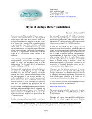
BATTERY CAPACITY SELECTIONFigures 1 and 2 may be used to determine battery size(expressed in Ampere Hours of capacity), for a specificapplication. To determine the capacity of the battery,establish the discharge current for the length of dischargetime required. The point where the current and time linesintersect is the minimum capacity battery needed for theapplication. It is recommended you refer to Figures 3,26, 30, & 31 before making your final decision.Figure 1. 20-HOUR RATE CAPACITY SELECTION CHARTAT 25ºC (77ºF)MINUTES HOURSDISCHARGE CURRENTRev. - 5/00— 5 —
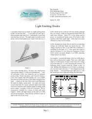
➞➞➞➞➞<strong>NP</strong>H SERIES CHARACTERISTIC CURVES➞108FIGURE 2. CAPACITY SELECTION CHART<strong>NP</strong>H SERIESAT 25ºC (77ºF)6DISCHARGE TIMEMINUTES ➞HOURS43260402010<strong>NP</strong>H2-12➞<strong>NP</strong>H3.2-1263100 200 300 400 600 800 1000 2 3 4 6 8 10 20mA➞A➞DISCHARGE CURRENTDISCHARGEDischarge CharacteristicsThe curves shown in Figures 1, 2, 3, & 4 and the dischargerates shown in Tables 1, 2, & 3 illustrate thetypical discharge characteristics of <strong>NP</strong> and <strong>NP</strong>H batteriesat an ambient temperature of 25 0 C (77 0 F). Thesymbol “C” expresses the nominal capacity of the <strong>NP</strong>battery, measured at a 20 hour discharge rate and the<strong>NP</strong>H at a 10 hour discharge rate. Please refer toGeneral Specifications to determine the nominalcapacity rating of the specific model.The industry standard for designating the nominalcapacity of a sealed lead acid battery involves a dischargetest for a given number of hours to a final presetend voltage. The average current value multipliedby the hours of discharge time determines the capacityrating of that particular battery. Since manufacturersvary in their rating standards, it is always a good practiceto question the rating standard.Tables 1 and 2 show how the rated nominal capacitydecreases when the discharge load is higher than the20 hour rate. These tables should be consulted whenselecting a battery for a high discharge application.The discharge rates depicted in Tables 2.5 referencewatts per cell of the <strong>NP</strong>X series of batteries. Thesebatteries are designed for Uninterruptable <strong>Power</strong>Supply (UPS) applications where high rate dischargeperformance (under 30 minutes) is typical. To determinethe battery kilowatt rating required for a UPS system,refer to the following formula:KVA rating of UPS x <strong>Power</strong> Factor (P f ) ÷ inverter efficiency= Total Battery Kilowatts (KWB).Rev. - 5/00— 6 —
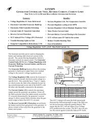
Figure 3.Discharge Characteristic Curves: <strong>NP</strong> BatteriesFigure 4.Discharge Characteristic Curves: <strong>NP</strong> BatteriesRev. - 5/00— 7 —
Table 1. DISCHARGE CURRENT AT STIPULATED DISCHARGE RATES20 H.R.Discharge CurrentCapacity 0.05C 0.1C 0.2C 0.4C 0.6C 1C 2C 3C0.8 A 0.04 A 0.08 A 0.16 A 0.32 A 0.48 A 0.8 A 1.6 A 2.4 A1.2 0.06 0.12 0.24 0.48 0.72 1.2 2.4 3.62.0 0.10 0.20 0.40 0.80 1.20 2.0 4.0 6.02.3 0.12 0.23 0.46 0.92 1.38 2.3 4.6 6.92.6 0.13 0.26 0.52 1.04 1.56 2.6 5.2 7.83.0 0.15 0.30 0.60 1.20 1.80 3.0 6.0 9.04.0 0.20 0.40 0.80 1.60 2.40 4.0 8.0 12.07.0 0.35 0.70 1.40 2.80 4.20 7.0 14.0 21.010.0 0.50 1.00 2.00 4.00 6.00 10.0 20.0 30.012.0 0.60 1.20 2.40 4.80 7.20 12.0 24.0 36.017.2 0.86 1.72 3.44 6.88 10.32 17.2 34.4 51.624.0 1.20 2.40 4.80 9.60 14.40 24.0 48.0 72.026.0 1.30 2.60 5.20 10.40 15.60 26.0 52.0 78.038.0 1.90 3.80 7.60 15.20 22.80 38.0 76.0 114.065.0 3.25 6.50 13.00 26.00 39.00 65.0 130.0 195.0Table 2. DISCHARGE CURRENT AT STIPULATED DISCHARGE RATES (<strong>NP</strong>H)10 Hr.Discharge CurrentCapacity 0.01C 0.2C 0.4C 0.6C 0.8C 1C 2C 3C2.0 0.20 0.40 0.80 1.20 1.40 2.00 4.00 6.003.2 0.32 0.64 1.28 1.90 2.54 3.20 6.40 9.60Table 2.5 <strong>NP</strong>X WATTS PER CELL TO 1.67 END VOLTAGETable 3. DISCHARGE CAPACITY AT VARIOUS DISCHARGE RATES5 MIN 10 MIN 15 MIN 20 MIN<strong>NP</strong>X-25 47 31 23 18<strong>NP</strong>X-50 94 60 50 38<strong>NP</strong>X-35 66 45 35 29<strong>NP</strong>X-80 155 104 80 65<strong>NP</strong>X-100 185 125 95 75<strong>NP</strong>X-150 285 200 150 120Discharge Capacity20 Hr. 20 Hr. 10 Hr. 5 Hr. 3 Hr. 1 Hr.Capacity 0.05CA to 1.75 V/C 0.093CA to 1.75 V/C 0.17CA to 1.70 V/C 0.25CA to 1.67 V/C 0.60CA to 1.55 V/C0.8 Ah 0.8 Ah 0.74 Ah 0.68 Ah 0.62 Ah 0.48 Ah1.2 1.2 1.1 1.0 0.9 0.72.0 2.0 1.9 1.7 1.6 1.22.3 2.3 2.2 2.0 1.8 1.42.6 2.6 2.4 2.2 2.0 1.63.0 3.0 2.8 2.6 2.3 1.84.0 4.0 3.7 3.4 3.1 2.47.0 7.0 6.5 6.0 5.4 4.210.0 10.0 9.3 8.5 7.7 6.012.0 12.0 11.2 10.2 9.2 7.217.2 17.2 16.0 14.6 13.2 10.324.0 24.0 22.3 20.4 18.5 14.426.0 26.0 24.2 22.1 20.0 15.638.0 38.0 35.0 32.3 29.3 22.865.0 65.0 60.5 55.2 50.1 39.0Rev. - 5/00— 8 —
Over-Discharge (Deep Discharge)The dotted line in Figures 3 & 4 indicates the lowest recommendedvoltage under load, or cut-off voltage, at variousdischarge rates. In general, lead acid batteries aredamaged in terms of capacity and service life if dischargedbelow the recommended cut-off voltages. It isgenerally recognized that all lead calcium alloy grid batteriesare subject to over-discharge damage. For example,if a lead acid battery were discharged to zero andleft in either open or closed circuit for a long period oftime, severe sulfation and shorting would occur, thusraising the internal resistance abnormally high. In suchan extreme case, the battery may not accept a charge.Yuasa <strong>NP</strong> <strong>Series</strong> batteries however, have beendesigned to withstand such occasional over discharge.While it is not recommended, <strong>NP</strong> batteries can recovertheir full capacity under normal charging conditions,even when they have been subjected to extreme overdischarge.Final discharge voltage is as shown in Table 4.Table 4. FINAL DISCHARGE VOLTAGEDischarge CurrentFinal Discharge Voltage (V/Cell)0.1 C or below, or Intermittent discharge 1.750.1 7C or current close to it 1.700.26C or current close to it 1.670.6C or current close to it 1.60From 0.6C to 3C 1.50Current in excess of 3C 1.30When considering discharge currents exceeding 3C, consultwith a Yuasa <strong>Application</strong> Engineer.STORAGE, SELF-DISCHARGE and SHELF LIFESelf-DischargeThe self-discharge rate of <strong>NP</strong> batteries is approximately3% per month when the storage temperature is maintainedat 20 0 C (68 0 F). The self-discharge rate will varywith storage temperature and the remaining capacity.Figure 5.SELF DISCHARGE CHARACTERISTICS(%)REMAINING CAPACITY20 0 CSTORAGE TIME (MONTHS)Rev. - 5/00— 9 —
Shelf LifeIn general, when lead acid batteries of any type arestored in a discharged condition for extended periods oftime, lead sulfate is formed on the negative plates of thebatteries. This phenomenon is referred to as “sulfation”.Since the lead sulfate acts as an insulator, it has a directdetrimental effect on charge acceptance. The moreadvanced the sulfation, the lower the charge acceptance.“Brief usage”, ie., a few days, at temperatures higherthan the ranges recommended, will have no adverseeffect on storage time or service life. However, if suchuse continues for more than one month, the storagetime must be determined according to the new ambienttemperature.Table 5 below shows the normal storage time or shelflife at various ambient temperatures.Table 5. Shelf Life at Various TemperaturesTemperatureShelf Life0 0 C ( 32 0 F) to 20 0 C ( 68 0 F)12 months21 0 C ( 70 0 F) to 30 0 C ( 86 0 F)9 months31 0 C ( 88 0 F) to 40 0 C (104 0 F)5 months41 0 C (106 0 F) to 50 0 C (122 0 F)2.5 monthsRecharging Stored BatteriesIn general, to optimize performance and service life, it isrecommended that <strong>NP</strong> batteries which are to be storedfor extended periods of time be given a supplementarycharge, commonly referred to as a “top charge”, periodically.Please refer to the recommendations listed onpage 20 under TOP CHARGING.IMPEDANCEThe internal resistance (impedance) of a battery is lowestwhen the battery is in a fully charged state. The internalresistance increases gradually during discharge, Figure 6shows the internal resistance of an <strong>NP</strong> battery measuredthrough a 1,000 Hz AC bridge.Figure 6. INTERNAL RESISTANCE OF <strong>NP</strong> BATTERYINTERNALRESISTANCE(mΩ)TERMINALVOLTAGE(V)BATTERY: <strong>NP</strong>7-12AMBIENT TEMPERATURE: 25 0 C (77 0 F)MEASURED WITH 1000Hz AC BRIDGEDISCHARGE TIME (HOURS)Rev. - 5/00— 10 —
Temperature characteristicsAt higher temperatures, the electrical capacity that canbe taken out of a battery increases. At lower temperatures,the electrical capacity that can be taken out of abattery decreases. Figure 7 shows the temperatureeffects in relation to battery capacity.Figure 7. TEMPERATURE EFFECTS IN RELATION TO BATTERY CAPACITYCHARGINGProper charging is one of the most important factors toconsider when using maintenance free sealed lead-acidbatteries. Battery performance and service life will bedirectly effected by the efficiency of the charger selected.The four charging methods are:Constant Voltage ChargingConstant Current ChargingTaper-Current ChargingTwo Step Constant-Voltage ChargingConstant-Voltage ChargingCharging at constant voltage is the most suitable, andcommonly used method for charging sealed lead-acidbatteries. Figures 8 through 13 show the charging characteristicsof <strong>NP</strong> batteries when charged by constantvoltage chargers at 2.30 volts/cell, 2.40 volts/cell and2.50 volts/cell, when the initial charging current is controlledat 0.1CA, and 0.25CA.Figure 8. CHARGING CHARACTERISTICSRev. - 5/00— 11 —
Figure 9. CHARGING CHARACTERISTICSFigure 10. CHARGING CHARACTERISTICSRev. - 5/00— 12 —
Figure 11. CHARGING CHARACTERISTICSFigure 12. CHARGING CHARACTERISTICSRev. - 5/00— 13 —
Figure 13. CHARGING CHARACTERISTICSFigure 14 shows one example of a constant voltagecharging circuit. In the circuit, initial charging currentis limited by series resistance R 1 .Figure 13. Recommended for overnight charge only.Figure 14. ONE EXAMPLE OF CONSTANT VOLTAGE CHARGING CIRCUITConstant-Current ChargingThis charging method is not often utilized for sealed leadacidbatteries, but is an effective method for charging amultiple number of batteries at one time, and/or as anequalizing charge to correct variances in capacitybetween batteries in a group.Caution should be exercised when charging by constantcurrent. If the charge is continued at the same rate for anextended period of time after the battery has reached afully charged state, severe overcharge may occur, resultingin damage to the battery.Figure 15 shows the characteristics of an <strong>NP</strong> batteryunder continuous overcharge conditions.Rev. - 5/00— 14 —
Figure 15. OVERCHARGE CHARACTERISTICS OF <strong>NP</strong>6-12 UNDER CONTINUOUS OVERCHARGEOVERCHARGING CURRENT:0.6A (0.1CA)AMBIENT TEMPERATURE: 25ºC (77ºF)CAPACITY TEST: 1.5A to 10.2V EVERY 100 HOURSn=2Figure 16 shows a typical constant current charging circuit.Figure 16. CONSTANT-CURRENT CHARGING CIRCUITTaper-Current ChargingDue to the constant characteristics of taper charging,this method is somewhat abusive of sealed lead-acidbatteries and can shorten service life. Consequently, it isnot widely recommended. However, because of the simplicityof circuit and subsequent low cost, taper-currentcharging is extensively used to charge multiple numbersof batteries and/or for cyclic charging. When using ataper charger, it is recommended that the charging timebe limited or a charging cut-off circuit be incorporated toprevent overcharge. Please consult the factory for specificrecommendations.In a taper-current charging circuit, the charge currentdecreases in proportion to the voltage rise. Whendesigning a taper charger, always consider commercialpower voltage variations which could create severecharging current fluctuations. In this event, the I R dropwill convert to heat. Therefore, heat generated by the circuitshould be measured, and if necessary, a heat sinkbe incorporated in the design. Figure 17 illustrates thecharacteristics of a typical taper-current charger.Rev. - 5/00— 15 —
Figure 17. CHARGING CHARACTERISTICS OF A TAPER CHARGERFigure 18. TAPER-CURRENT CHARGING CIRCUITSTwo step constant voltage charging is the recommendedmethod for charging a sealed lead-acid battery in ashort period of time, and maintaining the battery in afully charged standby or float condition, thereafter.Figure 19 illustrates the characteristics of a two stepconstant voltage charger.Figure 19. CHARGING CHARACTERISTICS OF A TWO STEP CONSTANT-VOLTAGE CHARGERRev. - 5/00— 16 —
The characteristics shown in Figure 19 are those of aconstant voltage, constant current charger. In the initialcharging stage, the battery is charged by constant current.The charging voltage rises, as the charge continues,until it reaches 2.45 volts per cell, at which pointthe charging mode automatically changes to constantvoltage charging. During the constant current chargingstage (A-B) the charging current which has decreasedto point B is sensed, and the charging voltage isswitched to the float level of 2.3 volts per cell from therecovery level of 2.45 volts per cell. The switch to constantvoltage trickle charging occurs after the batteryhas recovered approximately 80% of the rated capacityover a given period of time.This charging method is one of the most efficient. Therecharge time is minimized during the initial chargingstage while the battery is protected from overcharge bythe system switching over to float charge at the switchingpoint B.Figure 20 illustrates an example of a two step constantvoltage, constant current charger. Basically, this is astablilized power supply circuit, with a current limitingfunction, utilizing hybrid IC constant voltage elements.The difference between this circuit and the constantvoltage circuit shown in Figure 14 is the addition of circuitVD which serves to increase or decrease the outputvoltage as a function of the variation in output current.In other words, the output voltage is establishedby changing, with resistor R 6 , the potential ratio of thedetected voltage of the IC which detects the reductionof voltage at both terminals of resistor R 1 .Figure 20. ONE EXAMPLE OF A TWO STEP CONSTANT-VOLTAGE CONSTANT-CURRENT CHARGING CIRCUITWhen this charging method is used, the output valuesSwitching Current Fromwill be as follows:1st Step to 2nd Step . . 0.05CA (0.04 to 0.08CA)Initial Charge Current .....0.25CA (to 1.OCA, max.)Charge Voltage -Note: This charging method cannot be used in1st Step. . . .2.45v/cell (2.35 to 2.47v/cell, max.)applications where the load and the battery2nd Step. . . 2.28v/cell (2.25 to 2.30v/cell, max.)are connected in parallel.Rev. - 5/00— 17—
Charging VoltageThe charging voltage should be regulated according tothe type of service in which the battery will be used.Generally, the following voltages are used:For standby (float) use ......2.25 to 2.30 volts per cellFor cyclic use .............2.35 to 2.47 volts per cellIn a constant voltage charging system, a large amount ofcurrent will flow during the initial stage of charging, anddecreases as the charging progresses. When chargingat 2.30 volts per cell, charging current at the final stageof charging will drop to as little as 0.002CA.The charge volume shown on the ordinate axis ofFigures 8 through 13 indicates the ratio of chargedampere-hours versus the previously discharged amperehours.When a battery has been charged up to the levelof 100% of the discharged ampere-hours, the electricalenergy stored and available for discharge will be 90%, ormore, of the energy applied during charging.Charging voltage should be regulated in relation to theambient temperature. When the temperature is higher,the charging voltage should be lower. When the temperatureis lower, the charging voltage should be higher. Forspecific recommendations, please refer to the section onTemperature Compensation on page 21.Similarly, charged volume (measured in ampere-hours)attainable over time will vary in direct relation to theambient temperature. The charged volume in a givenperiod of time will be larger at higher temperatures, andsmaller at lower temperatures. Figure 21 shows the relationshipbetween charged volume and temperature.Figure 21. CHARGING CHARACTERISTICS AT DIFFERENT TEMPERATURERev. - 5/00— 18 —
Initial Charge Current LimitA discharged battery will accept a high charging currentat the initial stage of charging. High charging currentcan cause abnormal internal heating which may damagethe battery. Therefore, it is recommended that thecharging current be normally limited to 0.25CA. However,in standby use, Yuasa <strong>NP</strong> batteries are designed so thateven if the charging current is higher than the recommendedlimit, they will not accept more than 2CA, and thecharging current will be reduced to a relatively small valuein a very brief period of time. Therefore, in standby use, nocurrent limit is required. Figure 22 shows current acceptancein <strong>NP</strong> batteries charged at constant voltage, with nocurrent limit.When designing a charger, it is recommended that acurrent limiting function be provided in the charger in orderto prevent charger failure due to overheating of the transformer,or other damage resulting from mishandling, i.e.,short circuiting or reversing polarity.Figure 22.CONSTANT-VOLTAGE CHARGECHARACTERISTICS WITH NOCURRENT LIMITCHARGE VOLTAGE: 2.30V/CTEMPERATURE: 25ºC (77ºF)Charge Output Regulation and AccuracyTo insure accuracy, when adjusting the output voltageof a constant voltage charger, all adjustments mustbe made with the charger under load. Adjusting theoutput voltage with the charger in a “NO LOAD” conditionmay result in undercharging. The constant voltagerange required by a battery is always defined asthe voltage range applied to a battery which is fullycharged. Therefore, a charger having the outputcharacteristics illustrates in Figure 23, should beadjusted with the output voltage based on point A.The most important factor in adjusting charger outputvoltage is the accuracy at point A. Stringent accuracyof 2.25 to 2.30 volts per cell is not required over theentire range of the load. A charger adjusted in accordancewith Figure 23 will never damage a battery,even if the charger has the characteristics shown bythe broken line in Figure 23.Figure 23. TAPER-CURRENT CHARGING CIRCUITSRev. - 5/00— 19 —
Top ChargingSince any battery loses capacity through self-discharge, itis recommended that a “top charging” be applied to anybattery which has been stored for a long period of time,prior to putting the battery into service. Excepting conditionsin which storage temperature have been abnormallyhigh, top charging is recommended within the followingparameters:Battery AgeWithin 6 monthsafter manufactureWithin 12 monthsafter manufactureTop Charging Recommendations4 to 6 hours at constant current of 0.1CA, or 15 to 20 hoursat constant voltage of 2.40 volts per cell.8 to 10 hours at constant current of 0.1CA, or 20 to 24 hoursat constant voltage of 2.40 volts per cell.In order to successfully top charge a battery stored formore than 12 months, the open circuit voltage must behigher than 2.0 volts per cell. In this case, always confirmopen circuit voltage prior to attempting top charging.Recovery Charge After Deep DischargeWhen a battery has been subjected to deep discharge(commonly referred to as over-discharge), the amount ofelectricity which has been discharged is actually 1.5 to 2.0times as great as the rated capacity of the battery.Consequently, a battery which has been over-dischargedrequires a longer charging period than normal. Pleasenote, as shown in Figure 24 below, that as a result ofinternal resistance, charging current accepted by an overdischarged<strong>NP</strong> battery during the initial stage of chargingwill be quite small, but will increase rapidly over the initial30 minutes (approximate) until internal resistance hasbeen overcome, and normal, full recovery charging characteristicsresume.Figure 24. TYPICAL CHARGING CHARACTERISTICS AFTER DEEP DISCHARGE0.25CA - 7.25V CONSTANT VOLTAGE CHARGE FOR 24 HOURSDEEP DISCHARGE: WITH 1.0 OHM RESISTOR FOR 24 HOURSAND STORED FOR 30 DAYS AT OPEN CIRCUIT CONDITIONAMBIENT TEMPERATURE: 25ºC (77ºF)Rev. - 5/00— 20 —
In view of the above, consideration should be given to thefact that if the charging method used is constant voltagein which the charger employs current sensing for eitherstate of charge indication or for reducing voltage (a twostep charger), during the initial stage of charging anover-discharged battery the charger may give a false “fullcharge” indication, or may initiate charge at a float voltage.Temperature CompensationAs temperature rises, electrochemical activity in a batteryincreases. Similarly, as temperature falls, electrochemicalactivity decreases. Therefore, conversely, as temperaturerises, charging voltage should be reduced to preventovercharge, and increased as temperature falls toavoid undercharge. In general, to assure optimumservice life, use of a temperature compensated charger isrecommended. The recommended compensation factorfor <strong>NP</strong> batteries is -3mV/ 0 C/Cell (stand by) and-4mV/ 0 C/Cell (cyclic use). The standard center point fortemperature compensation is 20 0 C (68 0 F).Figure 25 shows the relationship between temperaturesand charging voltages in both cyclic and standbyapplications.Figure 25. RELATIONSHIP BETWEEN CHARGING VOLTAGE AND TEMPERATUREIn actual use in indoor applications (5 0 C to 40 0 C or 41 0 Fto 104 0 F), it is not necessary to provide the charger witha temperature compensation function, but it is desirableto set the voltage at the value shown in Figure 25 whichcorresponds most closely to the average ambient temperatureof the battery during service.When designing a charger equipped with temperaturecompensation, the temperature sensor must sense onlythe temperature of the battery. Therefore, considerationshould be given to isolating the battery and temperaturesensor from other heat generating components of a systemRev. - 5/00— 21 —
Charging EfficiencyThe charging efficiency (η) of a battery is expressedby the following formula:Figure 26. CHARGING EFFICIENCY VSSTATE OF CHARGEη=AH Discharged After ChargedAH Delivered To The Battery During ChargeThe charging efficiency varies depending upon thestate of charge of the battery, temperature, and chargingrate.Figure 26 illustrates the concept of the state of chargeand charging efficiency.As shown in Figure 27, Yuasa <strong>NP</strong> batteries exhibitvery high charging efficiency, even when charged atlow charging rates. It is interesting to note that thecharging efficiency of <strong>NP</strong> sealed lead-acid batteries issuperior to that of nickel cadmium batteries even atrelatively low charge rates.Figure 27. CHARGING EFFICIENCYRev. - 5/00— 22 —
Solar <strong>Power</strong>ed ChargersA battery is an indispensable component of any solarpowered system designed for demand-energy use.Since solar cells have inherent constant voltage characteristics,<strong>NP</strong> batteries can be charged directly fromthe solar array using a simple diode regulated circuitas shown in Figure 28.Figure 28. BLOCK DIAGRAM OF A SOLAR SYSTEMIn designing a solar system, consideration should begiven to the fact that, in addition to normal periodsof darkness, weather conditions may be such thatsolar energy is limited, or virtually unavailable forlong periods of time. In extreme cases, a system mayhave to operate for 10 to 20 days with little or nopower available for charging. Therefore, when selectingthe correct battery for a solar application, thecapacity should be determined based upon maximumload conditions for the maximum period of timethe system may be expected to be without adequatesolar input.In many instances the battery capacity will be 10 to50 times greater than the maximum output of thesolar panels. Under these circumstances, the maximumoutput of the solar array should be dedicated tocharging the battery with no load-sharing or interveningcontrol devices of any kind.Naturally, in cases where the output of the solar arrayexceeds the capacity of the battery, and weatherconditions are such that the potential for overchargingthe battery exists, appropriate regulated chargingcircuitry between the solar panels and the battery isrecommended.Remote site, or other outdoor applications for solarsystems is commonplace. When designing a solar systemfor this class of application, a great deal of considerationmust be given to environmental conditions.For example, enclosures which may be used to housebatteries and other equipment may be subject toextremely high internal temperatures when exposed todirect sunlight. Under those conditions, insulating theenclosure and/or treating the surface of the enclosurewith a highly reflective, heat resistive material is recommended.In general, when designing a solar system, consultationwith the solar panel manufacturer and batterymanufacturer is recommended.EXPECTED SERVICE LIFE OF <strong>NP</strong> BATTERIESCyclic Service LifeThere are a number of factors that will effect thelength of cyclic service of a battery. The most significantare ambient operating temperature, dischargerate, depth of discharge, and the manner in which thebattery is recharged. Generally speaking, the mostimportant factor is depth of discharge. Figure 29 illustratesthe effects of depth of discharge on cyclic life.Rev. - 5/00— 23 —
Figure 29. CYCLE SERVICE LIFE IN RELATION TO DEPTH OF DISCHARGE <strong>NP</strong> SERIESPERCENTAGE OF CAPACITY AVAILABLE(AH%)120100806040200TESTING CONDITIONS: DISCHARGE CURRENT: 0.17C AMP. (F.V. 1.7V/CELL)CHARGING CURRENT: 0.09C AMP.CHARGING VOLUME: 125% OF DISCHARGED CAPACITYAMBIENT TEMPERATURE: 20°C TO 25°C (68°F TO 77°F)100% D.O.D. 50% D.O.D. 30% DEPTH OF DISCHARGE200 400 600 800 1000NUMBER OF CYCLES (CYCLES)1200 1400The relationship between the number of cycles whichcan be expected, and the depth of discharge is readilyapparent. In relation to a specified discharge rate, ifthe application requires a longer cyclic life than isobtainable by selecting the battery capacity accordingcommon practice, select a battery with larger capacity.Thus, at the specified discharge rate over the specifiedtime, the depth of discharge will be shallower andcyclic service life will be longer.Float Service Life<strong>NP</strong> batteries are designed to operate in standby (float)service for approximately 5 years, based upon anormal service condition in which float charge voltageis maintained between 2.25 and 2.30 volts per cell inan ambient temperature of approximately 20 0 C (68 0 F).Figure 30 shows the float service life characteristics of<strong>NP</strong> batteries when discharged once every three (3)months to 100% depth of discharge.Figure30. FLOAT SERVICE LIFETESTING CONDITIONS: FLOATING VOLTAGE: 2.25 to 2.30V/CELLAMBIENT TEMPERATURE: 20ºC TO 22ºC (68ºF TO 72ºF)In normal float service, where charging voltage is maintained2.25 to 2.30 volts per cell, the gases generatedinside and <strong>NP</strong> battery are continually recombined, andreturn to the water content of the electrolyte. Therefore,electrical capacity is not lost due to “drying up” of theelectrolyte. Actually, through the gradual and very slowcorrosion of the electrodes, the battery will eventuallylose capacity and come to the end of service life. Itshould be noted that the corrosive process will be acceleratedby high ambient operating temperatures and/orhigh charging voltage. When designing a float servicesystem, always consider the following:LENGTH OF SERVICE LIFE WILL BE DIRECTLYEFFECTED BY THE NUMBER OF DISCHARGECYCLES, DEPTH OF DISCHARGE, AMBIENTTEMPERATURE, AND CHARGING VOLTAGE.Rev. - 5/00— 24 —
TIPS AND PRECAUTIONSYuasa <strong>NP</strong> <strong>Series</strong> batteries are truly efficient maintenance free electro-chemical systems and are designed to provide yearsof trouble free service. Their performance and service life can be greatly maximized by observing the following guidelines.1.2.3.4.5.6.7.Heat kills batteries. Avoid installation and/or operationin close proximity to heat sources of any kind. Whilethe operating temperature range is -15°C to 50°C,and ideal service life will be realized when the batteryis operated in an ambient temperature of 20°C (forcyclic service applications, a range of 5°C to 35°C isrecommended).If the battery is to be installed in an air or water tightcontainer, ventilation must be provided. Batteries maygenerate ignitable gases which must not be contained.Because of this, batteries should not beinstalled near spark producing equipment.Avoid installing the battery in an atmosphere whereorganic solvents or adhesives may be present. Do notclean the battery with oils, thinners or similar substances.Use water. only. The case and cover of thebattery is ABS plastic resin which may suffer damagefrom these chemicals.Soldering to the battery terminals is NOT recommended.If soldering is unavoidable, it must beaccomplished within 3 seconds, using a maximum100 watt soldering iron.If installed in a heavy vibration or shock application,the battery must be securely fastened with shockabsorbing materials.Provide free air space between batteries when morethan two are grouped together. The recommendeddistance is 0.2" to 0.4" (5mm to 10mm).Always wear insulated gloves when handling batteries;especially when series and parallel connectinggroups of batteries.8.9.10.11.12.13.When batteries are connected together in a seriesparallelarrangement, the inter-connecting cablesmust be of equal length and resistance to insureequalization of the load.For maximum life expectancy, the R.M.S. ripple currentshould be regulated to no more than 0.1C (10%of battery's rating).Do not crush, incinerate or dismantle the battery. Theelectrolyte contains sulfuric acid which can cause seriousdamage to eyes and skin. Should this occur, flushprofusely with water and seek medical attention.Mixing batteries of different capacities, age and/ormanufacture is not recommended. Please consult withan application engineer if it is unavoidably necessary.Battery life is dependent on its operating conditions.Please refer to the life curves published in this<strong>Application</strong>s <strong>Manual</strong>. These curves represent typicalresults under optimum operating conditions. Actual lifewill vary greatly due to variability of these conditions.To obtain optimum battery performance for standbyservice, Yuasa, Inc. recommends that within five yearsof use, the <strong>NP</strong> batteries be replaced.Observe the external appearance of the battery. If, atany time, cracks, deformation or other damage isfound on the battery case or cover, or if any leakageof the electrolyte is observed, immediately replace thebattery.Note: If a battery with any irregular appearance asstated above is used continuously, a decrease incapacity, leak age of electrolyte, short circuits anda potential for a smoke and/or fire incident may occur.GLOSSARY OF TERMSActive Material . . . . . . . . . . . . The active electro-chemical materials used in the manufacture of positive and negativeelectrodes.Ambient Temperature . . . . . . . The average temperature seen by the battery.Available Capacity . . . . . . . . . The capacity from the battery based on its state of charge, rate of discharge, andambient temperature.Battery . . . . . . . . . . . . . . . . . . Two or more cells, series connected together. A single cell is sometimes referred to asa battery.C-Rate . . . . . . . . . . . . . . . . . . A current rate expressed in amperes or milliamperes, in direct relation to a battery'sampere hour rating. Ex: 6 Ah rating, 1C = 6 amps; 3C = 18 Amps; 0.05C = 300milliampsCA . . . . . . . . . . . . . . . . . . . . . C Ampere; the C-rate of a battery measured in amperes.Capacity Fade . . . . . . . . . . . . Loss of capacity due to inadequate recharging.Cell . . . . . . . . . . . . . . . . . . . . . The minimum unit of which a storage battery is composed. Note: The nominal voltageof a single lead acid cell is 2.0 volts.Closed Circuit Voltage Test . . . A test method in which the battery is briefly discharged at a constant current while thevoltage is measured.Constant Voltage Charge . . . . A method of charging batteries by applying a fixed voltage and allowing the current tovary. Recommended for sealed lead acid batteries. (Also called constant potentialcharge).Rev. - 5/00— 25 —
GLOSSARY OF TERMS (Continued)Cutoff Voltage . . . . . . . . . . . . . The final voltage of a cell or battery at the end of charge or discharge.Cycle . . . . . . . . . . . . . . . . . . . A single charge and discharge of a cell or battery.Discharge Rate . . . . . . . . . . . . Current taken from a cell or battery and expressed as a fraction of C (Ampere-hourrating of the cell or battery).End-of-Charge Voltage . . . . . . The voltage reached by the cell or battery at the end-of-charge, while the charger isstill attached.Electrolyte . . . . . . . . . . . . . . . Conducts ions in the cell. Lead acid batteries use a sulfuric acid solution.Energy Density . . . . . . . . . . . . Ratio of cell or battery energy to weight or volume: watt-hours per pound or per cubicinch.Gas Absorption . . . . . . . . . . . The ability of the negative plate to absorb oxygen gas generated within the battery; thegreater this ability, the greater the charge current capability.High-Rate Discharge . . . . . . . A very rapid discharge of the battery. Normally in multiples of C (Ampere-hour ratingof the cell or battery).Internal Impedance . . . . . . . . . The resistive value of the battery to an AC current, expressed in ohms. Normally measuredat 1 khz at full charge.Low Voltage Cutoff . . . . . . . . . A sensing device designed to end discharge at a predetermined voltage level.Nominal Capacity . . . . . . . . . . The nominal value of rated capacity. In sealed lead acid batteries, nominal capacity isusually measured at the 20 hour rate.Nominal Voltage . . . . . . . . . . . The nominal value of rated voltage. In lead acid batteries, nominal voltage is 2 voltsper cell.Open Circuit Voltage . . . . . . . . The measured voltage of the cell or battery without a load attached.Overcharge . . . . . . . . . . . . . . The continuous charging of a cell after it achieves 100% of capacity. Battery life isreduced by prolonged over charging.Parallel Connection . . . . . . . . . Connection of a group of batteries by inter-connecting all terminals of the same polarity,thereby increasing the capacity of the battery group. (Note: Differing brands and/orcapacities should not be connected together).Primary Cell . . . . . . . . . . . . . . A cell which can be discharged only once. Example: Manganese zinc and alkaline.Rated Capacity . . . . . . . . . . . . The capacity of the cell expressed in ampere hours. Commonly, a constant current fora designated number of hours to a specified depth of discharge at room temperature.Resealable Safety Vent . . . . . . The safety device built into the cell to allow the release of excess gases and preventcase rupture.Secondary Battery . . . . . . . . . A battery which can be charged and discharged repeatedly. Example: Lead acid andnickel cadmium batteries.Self Discharge . . . . . . . . . . . . The loss of capacity of a battery while in stored or unused condition without externaldrain.Separator . . . . . . . . . . . . . . . . The materials which separate the electrodes. In a sealed lead acid battery, they areusually constructed of micro-porous glass fiber and additionally serve to retain theelectrolyte.<strong>Series</strong> Connection . . . . . . . . . Connection of a group of batteries by interconnecting all terminals of the oppositepolarity, thereby increasing the voltage of the battery group. (Note: The same rule appliesas with parallel connections).Service Life . . . . . . . . . . . . . . Expected life of a battery expressed in the number of total cycles or years of standbyservice to a designated remaining percentage of original capacity.Shelf Life . . . . . . . . . . . . . . . . The maximum period of time a battery can be stored under specific conditions, withoutsupplementary charging.Standby Service . . . . . . . . . . . A general term for an application in which the battery is maintained in a fully chargedcondition by trickle or float charging and always ready for use.Trickle Charge . . . . . . . . . . . . Continuous charging by means of a small current designed to compensate for self dischargein an unloaded battery.Voltage Cutoff . . . . . . . . . . . . . A sensing device used to terminate a charge or discharge when the battery reaches apredetermined voltage level.Rev. - 5/00— 26 —
LIMITED WARRANTY:Each Yuasa <strong>NP</strong> <strong>Series</strong> battery which is sold is warrantedagainst defects in workmanship and materials for a period ofone year from the data of manufacture. Under this warranty,our obligation will be limited to the repair or replacement ofthe battery. Such repair or replacement will be FOB ourwarehouse in City of Industry, California or other designatedlocation that Yuasa, Inc. may designate. Such repair orreplacement will be made only after our examination determinesthat said battery is defective in material and/or workmanship.We exempt from any warranty claims and any batterywhich has been subjected to misuse, abuse, altered, orany battery that may have been repaired or attempted to berepaired by other than Yuasa, Inc.THIS WARRANTY MADE IN LIEU OF ALL OTHERWARRANTIES WITH RESPECT TO THE PRODUCTCOVERED HEREBY AND THERE ARE NO OTHERWARRANTIES, WHETHER EXPRESSED ORIMPLIED, OR MERCHANTABILITY OR OTHERWISEEXCEPT THE WARRANTY EXPRESSLY STATEDHEREIN. THE REMEDY SET FORTH HEREINSHALL BE THE SOLE EXCLUSIVE REMEDY OFANY PURCHASER WITH RESPECT TO ANYDEFECTIVE PRODUCT, UNDER NO CIRCUM-STANCES SHALL WE BE LIABLE FOR ANYINJURY, LOSS, DAMAGE, OR EXPENSE SUF-FERED OR INCURRED WITH RESPECT TO ANYDEFECTIVE PRODUCT.When ordering new batteries, also remember the need to properly dispose (recycle) your oldlead-acid batteries.Most federal and state regulations require lead-acid batteries be recycled. Yuasa, Inc'snationwide service organization can arrange pickup, transportation, and recycling to anyone of our company affiliated smelters. Call 1-800-972-7372 for more information.Rev. - 5/00
Rev. - 5/00NOTES
Rev. - 5/00NOTES
Eastern Regional Office: (201) 964-0118 (800) 962-1287Western Regional Office: (562) 949-4266 (800) 423-4667Corporate Office: P.O. Box 14145, Reading, PA 19612-4145fax: (610) 372-8613Visit us on the web at: www.yuasastationary.comPlease check our website for literature updatesPrinted 5/00 - 3,000Rev. - 5/00Printed in USA
![G-Series-Ext [pdf] - Carling Technologies](https://img.yumpu.com/50918301/1/190x245/g-series-ext-pdf-carling-technologies.jpg?quality=85)