r - Biblioteca Digital do IPB - Instituto Politécnico de Bragança
r - Biblioteca Digital do IPB - Instituto Politécnico de Bragança
r - Biblioteca Digital do IPB - Instituto Politécnico de Bragança

You also want an ePaper? Increase the reach of your titles
YUMPU automatically turns print PDFs into web optimized ePapers that Google loves.
A New Online I<strong>de</strong>ntification Metho<strong>do</strong>logy for Flux and ParametersEstimation of Vector Controlled Induction MotorsVicente Leite (1) , Rui Araújo (2) , Member, IEEE, Diamantino Freitas (3)(1) <strong>Instituto</strong> Politécnico <strong>de</strong> Bragança - Escola Superior <strong>de</strong> Tecnologia e <strong>de</strong> GestãoCampus <strong>de</strong> Sta. Apolónia - Aparta<strong>do</strong> 134, 5301-857 Bragança, Portugal, avtl@ipb.pt(2), (3) Faculda<strong>de</strong> <strong>de</strong> Engenharia da Universida<strong>de</strong> <strong>do</strong> PortoRua Dr. Roberto Frias s/n, 4200-465 Porto, Portugal, (2) raraujo@fe.up.pt, (3) dfreitas@fe.up.ptAbstract 1 - A new online i<strong>de</strong>ntification metho<strong>do</strong>logy forestimation of the rotor flux components and the main electricalparameters of vector controlled induction motors is presented inthis paper. The induction motor mo<strong>de</strong>l is referred to the rotorreference frame for estimation of rotor flux and rotorparameters, and referred to the stator reference frame toestimate stator parameters. The stator parameters estimation isachieved by a prediction error method based on a mo<strong>de</strong>lstructure <strong>de</strong>scribed by a linear regression that is in<strong>de</strong>pen<strong>de</strong>nt ofrotor speed and rotor parameters. The rotor flux componentsand rotor parameters are estimated by a reduced or<strong>de</strong>rexten<strong>de</strong>d Kalman filter, using a 4 th -or<strong>de</strong>r state-space mo<strong>de</strong>lstructure where the state equation is <strong>de</strong>scribed by matrices thatare diagonal and in<strong>de</strong>pen<strong>de</strong>nt of rotor speed as well as statorparameters. Both methods work in a boot-strap manner.I. INTRODUCTIONIn recent years, the availability of digital signal processorsand the fast <strong>de</strong>velopment of mo<strong>de</strong>rn power electronics havecontributed to the wi<strong>de</strong> acceptance of the prevailing vectorcontrol in high-performance induction motor (IM) drives, andhave ma<strong>de</strong> the correct estimation of the rotor flux and theadaptation of the system to changing motor parametersfeasible, which are two major problems in theimplementation of such industrial applications as referred in[1]. The recent trend is to implement a solution with jointonline estimation of IM states and parameters [1-5].However, the simultaneous estimation of the two rotor fluxcomponents and all electrical parameters of a vectorcontrolled induction motor, un<strong>de</strong>r normal operatingconditions, for real-time implementations, remains achallenge. This work is a new contribution for this purpose.The main goal is to achieve the simultaneous estimation offlux and electrical parameters in real time operation, with aslow computational effort as possible, un<strong>de</strong>r normal operatingconditions and with in<strong>de</strong>pen<strong>de</strong>nt and flexible estimators inor<strong>de</strong>r to adjust the i<strong>de</strong>ntification procedure to the dynamicconditions of the machine.II. INDUCTION MOTOR MODELIn previous works [4, 5] the authors have shown that thejoint estimation of rotor flux components and all the electricalThe authors would like to acknowledge the financial assistance provi<strong>de</strong>d byFundação Luso-Americana.parameters of a per-phase IM mo<strong>de</strong>l <strong>de</strong>scribed by fourparameters [6], is feasible in real time applications by usingan exten<strong>de</strong>d Kalman filter (EKF) technique, with reduction ofcomputational effort, based on a reduced or<strong>de</strong>r mo<strong>de</strong>l in therotor reference frame as shown below:⎡ψ&⎢⎢⎣ψ&ursdrrdrrqwhere:τr⎤ ⎡− τ⎥ = ⎢⎥⎦⎢⎣0= −τ− 1r−1rψψ= L R ,r−1rrrdrrd0− τ− ωψ−1rrrq⎤ ⎡ψ⎥ ⎢⎥⎦⎢⎣ψ+rrdrrq−1rt ) = LmLrrd ( t)⎤ ⎡LMτ⎥ + ⎢⎥⎦⎢⎣0−1r0L τM−1r⎤ ⎡i⎥ ⎢⎥⎦⎢⎣irsdrsq⎤⎥ (1)⎥⎦−1r ' r r( R + L τ ) i + L ( i&− ωi)s( φ'2 −1s = Ls− LmLrML and,rsdψrrqssdsq(2)−1rt ) = LmLrrq(t)( φ2 −1M = LmLrL .The simultaneous estimation of the four electricalparameters requires some dynamic conditions for a correcti<strong>de</strong>ntification of stator parameters [4, 5], namely, Rsand L ' s .In any case the estimation of these parameters remains hardto <strong>do</strong>, wherefore another procedure is presented in the nextsection. Oppositely, the other two motor parameters,τrand L M , can be estimated whether in transient conditionsor in steady-state operation with a good robustness withrespect to errors in the stator parameters [4]. According tothis fact, the authors propose a new metho<strong>do</strong>logy that enablesthe estimation of the main parameters but separates theestimation of τ r , L M and the rotor flux components fromthe stator parameters.III. THE IDENTIFICATION METHODOLOGYThe proposed metho<strong>do</strong>logy consists of a first estimatorthat uses the EKF to find good estimates of the parameters τ rand , and the two rotor flux components, followed by aL Mrecursive prediction error based estimator (RPEM) to obtainthe stator resistance and either the transient stator inductance,'L s , or the stator inductance,L s , estimated values, togetheror separately, in a boot-strap manner. Thus, consi<strong>de</strong>ring aspecific instant, t k , the EKF is used for estimation of theexten<strong>de</strong>d and scaled state vector x ) , based on previous,0-7803-7817-2/03/$17.00 ©2003 IEEE449
estimated values of stator parameters and then, a RPEM isused to estimate the parameter vector θ ) , which corresponds'to the scaled parameters L s (or L s ) and R s . The state vector xand the parameter θ are scaled by constants K i ’s, fornumerical reasons, as follows:) ) ) ) ) )x(k,θ−) ==[ x ( k)x ( k)x ( k)x ( k)]1rr−1[ k ψ ( k)k ψ ( k)k τ ( k)k L ( k)]1t krd12rq2) )'θ(k,xt k) = k5Ls( k)or) )θ( k,x ) k6R( k)ort k=3s'[ k L ( k)k R ( )]) )θ( k,xt k) = s 635 s k44M=(3)(4a)(4b). (4c)For the EKF algorithm, the mo<strong>de</strong>l structure is formed by anonlinear discrete state space 4 th -or<strong>de</strong>r mo<strong>de</strong>l, obtained bydiscretization of state equation in (1), and the output equationin (2), as presented in [5] and results as follows, where T s isthe sampling period:⎡r⎤ ⎡−1ψrd( k + 1) 1−Tsτr0⎢ r ⎥ = ⎢⎢⎣ψrq(k + 1) ⎥⎦⎢⎣0 1−Tsτ⎡−1τ 0 ⎤ ⎡rT( ) ⎤sLMrisdk+ ⎢−1⎥⎢ r ⎥⎢⎣0 TsLMτr⎥⎦⎢⎣isq(k)⎥⎦ursd= −τ)( k)− R i−1rψrrdrs sd)'( k)− Ls( k)− ω(k)ψ−1r⎤ ⎡ψ⎥ ⎢⎥⎦⎢⎣ψrrdrrq( k)⎤⎥ +( k)⎥⎦( i&rr( t ) − ω(k)i ( k))sdrrqk( k)+ Lsq−1rM τrisd=( k)As we can see, the state equation in (5) is in<strong>de</strong>pen<strong>de</strong>nt ofrotor speed and stator parameters. Moreover, the matrices arediagonal and, therefore, it becomes very simple to get higheror<strong>de</strong>r approximation in the discretization process. The rotorspeed and stator parameters only appear in the outputequation in (6) where the measured output is a function of thestator parameters which are estimated by using the mo<strong>de</strong>lstructure <strong>de</strong>scribed bellow.For the recursive prediction error based method, a linearregression mo<strong>de</strong>l structure is used, which is <strong>de</strong>rived from thestator voltage equation, expressed in the stator referenceframe, as follows:ussd(5)(6)s ' ss( k)= R i ( k)+ L ( k)i& ( t ) + ψ) & ( t ) . (7)s sdObviously, instead of the d components in (7), the q onescould be selected. The equation above can then be rewrittenas a general linear regression as follows:)y( k,x)= θ(k)u(k)(8)ssdkrdkwhere, for the case of full estimation, like in (4c), we have:andssy k,x) ) = u ( k)− ψ) & ( t )(9)( sd rd ks ' sθ ( k ) u(k)= R i ( k)+ L ( k)i&( t ) . (10)s sdAs we can verify the equations (9) and (10), <strong>de</strong>scribed asa linear regression like in (8), <strong>do</strong> not <strong>de</strong>pend on neither therotor parameters nor the rotor speed. However, they <strong>de</strong>pen<strong>do</strong>n rotor flux d (or q) component’s first <strong>de</strong>rivative. The first<strong>de</strong>rivatives in (9) and (10) are computed by the followinggeneral recursive filter that can be found in [7], in or<strong>de</strong>r toobtain better results than by using Euler’s formula,n∑ − 1s i=0s1x& = dx / dt ≈ C ( − )t=ti x tkiTs(11)k TThe weights C i can also be found in [7] and are<strong>de</strong>termined after Taylor series expansion of the equationabove to m+1 terms, with m = { 1,2, L,n}, m being the or<strong>de</strong>rof the filter and n the number of points. For systemi<strong>de</strong>ntification purposes, as in this case, an important aspect totake into account is the <strong>de</strong>lay introduced by the filter. The<strong>de</strong>lay must be the same as the one introduced by the Euler’sformula that is implicit in the discretization process of sateequation in (1) if the linear terms of the Taylor’s <strong>de</strong>velopmentare a<strong>do</strong>pted as in (5). For sampling frequencies below 5kHz,the set of coefficients [ 11 − 18 9 − 2] / 6 , has producedthe best results. This is an unusual discretization process.In<strong>de</strong>ed, this strategy presented by the authors in [4, 5] hasbeen proven to give better results.This metho<strong>do</strong>logy is similar to an adaptive state estimatorfor nonlinear systems <strong>de</strong>scribed, in general terms, in [8] andapplied here for joint state and parameter estimation. The setupin fig. 1 is a very natural and simple way to achieve thisobjective. Beyond the advantage of separating the estimationof τ r , L M and the rotor flux components from the statorparameter, by adapting the estimator to the machine operatingpoint or, in other words, to the information contained in themeasured signals, it permits to overcome many of thedisadvantages associated with the EKF, namely, a strongcomputational effort, eventually biased estimates, and notguaranteed convergence [8]. Furthermore, this can be a goodalternative to the exten<strong>de</strong>d Luenberger observer suggested in[1] to solve the steady-state bias problem <strong>de</strong>tected in the jointrotor flux and rotor time constant estimation, and analternative to [2, 3], in terms of computational effort.As far as the induction motor is concerned the mainadvantage of this metho<strong>do</strong>logy is that it enables thesimultaneous estimation of rotor flux components and rotorparameters by using the EKF, and the estimation of statorparameters by using a RPEM based approach for jointestimation of stator parameters or even two RPEMs forin<strong>de</strong>pen<strong>de</strong>nt estimation of these parameters.sdk450
The in<strong>de</strong>pen<strong>de</strong>nce of the two or three algorithms, asrepresented in fig. 2(a) and (b), is really very important sincethe operating conditions of the induction motor required for asuccessful simultaneous estimation of all electricalparameters, are quite different for the four parameters.In [4, 5] the authors have shown that both rotorparameters (τ r and L M ) are well estimated even in steady-stateoperation and, due to this, they are proposed to be estimatedtogether with rotor flux components in every iteration. On theother hand, stator transient inductance needs significantdynamic conditions which are different from the ones nee<strong>de</strong>dfor stator resistance estimation that should be estimated atslow rotor speed where the term R si sd in (6) becomesimportant improving, by this way, the sensibility of the mo<strong>de</strong>lstructure in relation to stator resistance. It can be easily seenthat at high speed that term is negligible when ad<strong>de</strong>d to statorvoltage in (6) and as a result, the stator resistance starts todiverge, although slowly.By using this new metho<strong>do</strong>logy the estimation of statorparameters can be separated from flux and the rotor oneswhich can be enabled or disabled according to the dynamicconditions of the induction motor and this is very importantto <strong>do</strong> and even mandatory. Furthermore, the EKF basedalgorithm that estimates rotor flux and rotor parameters canupdate, at every iteration, the values of the stator parametersin its output equation, from time to time, or only when theyare properly available by the respective RPEM algorithmssince these can not be, necessarily, always working. Figures 1and 2 represent the above <strong>de</strong>scribed i<strong>de</strong>ntification strategy.Stator reference frameRPEM)Ty( k,x)= u(k)θ ( k)Forgetting factor, Kalman filter,gradient and other approachesse − jδ( k −1)ψ ) rd (k) ψ ) rd (k)rRotor reference frameEKFx(k + 1)y(k)= h= f ( x(k),u(k)) + rs( k)( x(k),θ ( k −1)) + r ( k)mθ ) )ussdssdssq( k),i ( k),i ( k)jδeursdrsdrsq( k),i ( k),i ( kenco<strong>de</strong>rrotor angle, δω(k)Fig. 1. The estimation metho<strong>do</strong>logy.EKFEstimationof τ rand L M(rotor ref. frame)1Z1ZRotorto statorRPEMEstimation of L ' s(stator ref. frame)RPEMEstimation of R s(stator ref. frame)'sL )ψ ) s srd ψ ), rq)τL )rMR )s1ZEKFEstimationof τ rand L M(rotor ref. frame)Rotorto statorRPEMEstimationof L ' s and R s(stator ref. frame)'s L ) sR )) s )ψ rd , ψ)τL ) r(a)(b)Fig. 2. The i<strong>de</strong>ntification metho<strong>do</strong>logy with in<strong>de</strong>pen<strong>de</strong>nt estimation of stator parameters and rotor states (parameters and flux components). (a) Separateestimation of stator parameters and (b) joint estimation of both stator parameters.srqMIV. SIMULATION RESULTSThe above-proposed estimator has been <strong>de</strong>veloped in theMATLAB with Simulink environment and tested un<strong>de</strong>r avector control scheme. Simulation conditions were selected tobe as close as possible of the experimental ones.Fig. 3 shows the simulation results where we can see therotor speed of a 2.2kW vector controlled induction motor aswell as the estimated flux and parameters, with the two statorparameters estimated by two recursive prediction error base<strong>de</strong>stimators as shown in fig. 2(a) and the results of a validationtest are also shown in figures 3(g) and 3(h).451
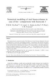
(a)(f)(b)(g)(c)(d)(e)(h)Fig. 3. Performance of the proposed i<strong>de</strong>ntification metho<strong>do</strong>logy for differentinitial seeds of stator parameters used by the EKF. (a) Generated electricalrotor speed by the vector control scheme, (b) estimated magnitu<strong>de</strong> of rotorflux, (c) estimated state x 3 - scaled inverse of rotor time constant, (d)estimated state x 4 - scaled magnetizing inductance, (e) estimated parameter θ 1- scaled stator transient inductance, (f) estimated parameter θ 2 - scaled statorresistance, (g) simulated/generated and estimated rotor flux q component and(h) generated stator current q component and the simulated one using theonline estimated parameters.One of the main difficulties of any full parameter and fluxestimator is the start-up procedure if no information isavailable beforehand about the electrical parameters. It iseven not possible to <strong>do</strong> it, since we search for too muchinformation as fluxes and parameters, based on just statorsignals and rotor speed and, on the other hand, the mo<strong>de</strong>lsensibility in relation to the stator parameters is low andstrongly <strong>de</strong>pen<strong>de</strong>nt of the dynamic conditions during thestart-up and immediately after. Due to this, a robust solutionis proposed here. We only need to have rough initial values ofthe electrical parameters for scaling the state vector x in (3)and parameter vector θ in (4). Many solutions can be used forthis purpose, some of them being very simple, such as452
classical methods or other rough parameter estimations as in[2], based on nominal characteristics of the induction motor.Within the estimation algorithms themselves, the onlyrequirement with respect to initial values of the electricalparameters is related to the initialization of stator parameters.Since in full estimation the rotor flux components are jointlyestimated with the electrical parameters, the algorithmshardly converge to correct values because of the lack ofconfi<strong>de</strong>nce in estimated flux components at the beginningand, on the other hand, the lack of sensibility of the inductionmotor mo<strong>de</strong>l with respect to stator parameters withoutspecific supply conditions.By this way, the EKF is started without any assumedknowledge of rotor parameters, but with initial seeds forstator parameters. Thus, 1 second after the EKF has beenstarted, when the rotor parameters and flux are supposed tobe close to the right values, the RPEM algorithm(s) is(are)started with rough estimates or even zero values in theparameter vector θ as used in (13). One second later allparameters and flux components are supposed to beconverging to their real values and the algorithms startworking according to the proposed i<strong>de</strong>ntificationmetho<strong>do</strong>logy.The initial values used in the algorithms are nowpresented. For the EKF, the initial state, the state covariancematrix and the system and measurement noise covariancematrices are, respectively:Rs(0) = Rx(0)=P(0)=Rs= diagR = 10ms− 50%;'s'sL (0) = L− 50%[ 0 0 0.1 0.1]diag[ 1e− 5 1e− 5 1e− 4 1e− 4][ 1e− 8 1e− 8 1e− 9 1e− 9]The RPEM algorithms were initialized as follows:θ (0) = 01P (0) = 1e− 3θ1RRs,θ1m,θ1= 1e− 7= 10θ (0) = 0P2θ2RR(0) = 1e− 3s,θ2m,θ2= 1e− 8= 10(12)(13)and they were based on the Kalman filter approach but otherapproaches can be used like forgetting factor (recursive leastsquares), normalized and unnormalized gradient approachesamong other recursive prediction error methods that can befound in [8] and [9].The scaling factors k 1 to k 6 referred in (3) and (4) were,respectively, 1, 1, 0.2, 5, 100 and 0.5.The simulation results shown in fig. 3 were obtained withthe configuration of fig. 2(a) and a square speed reference inthe range -600 to +600rpm, in or<strong>de</strong>r to ensure persistentenough excitation of the stator transient inductance from thetransient conditions, and stator resistance from the low speedzones, where the term R s i s becomes important in the virtualmeasured output of the output equation expressed by (6).In or<strong>de</strong>r to prove the robustness of the proposedmetho<strong>do</strong>logy with respect to initial seeds of stator parametersin the EKF based algorithm, three runs were achieved withdifferent initial seeds: In the first one the initial seeds werema<strong>de</strong> equal to the parameters’ real values and in the secondand third they were ma<strong>de</strong> equal to 50% below and above ofits real values, respectively. The results are presented infigures 3(b) to 3(f). The steady-state errors in all estimatedparameters are less than 2%, and the estimated flux waveformvery closely matches the simulated one as shown in fig. 3(g).Also the simulated stator current matches the “measured” one(generated by the vector control scheme) using the onlineestimated parameters, as can be seen in fig. 3(h).V. EXPERIMENTAL RESULTSExperimental results, shown in fig. 4, proved thefeasibility and applicability of the metho<strong>do</strong>logy <strong>de</strong>scribed inthe previous sections, and the results of a practicalexperiment were recor<strong>de</strong>d to validate the proposed strategy,and confirm the simulation results presented in the abovesection. In the practical experiment the stator voltages andstator currents, expressed in the stator reference frame, havebeen sampled at 5 kHz. Elliptic low-pass pre-filters of fifthor<strong>de</strong>r with a 500Hz cutoff frequency have been used on thesamples. Specific hardware was <strong>de</strong>veloped that has thesignals available in the range of ±10V in both rotor and statorreference frames, by using the AD2S100 analogue processor,but only the stator-referred signals are used for this work. Thestator voltages and currents are acquired in the statorreference frame with a data acquisition system that consistsof the dSPACE <strong>de</strong>velopment system, ACE Kit 1103, base<strong>do</strong>n the DS1103 PPC controller board, the Real Time Interface(RTI) blockset for Simulink as well as experiment software(ControlDesk, MLIB/MTRACE). The dSPACE <strong>de</strong>velopmentplatform was used for the real time i<strong>de</strong>ntification task and notfor control.The rotor position and speed, nee<strong>de</strong>d for reference frameconversions, are obtained via an incremental enco<strong>de</strong>r. For theEKF the stator voltages and currents are converted into therotor reference frame and the estimated rotor flux dqcomponents are converted into the stator reference frame.<strong>Digital</strong> filters, with the same specifications as the analogones, were used for filtering the computed rotor speed fromrotor angle as well as electrical signals after being acquired.Unfortunately, both filters introduce <strong>de</strong>lays. In or<strong>de</strong>r tosynchronize all the signals, the rotor angle and filtered speedhad to be suitably <strong>de</strong>layed. A 2.2KW induction motorcontrolled by an industrial frequency converter from ABB hasbeen used. The motor was loa<strong>de</strong>d by a pow<strong>de</strong>r break whichwas programmed for 12Nm, about half of the nominal torque.The vector control scheme <strong>de</strong>veloped by us in Simulink453
used in the simulation experiment and the one implementedby the ABB converter are naturally different. On the otherhand, the electrical parameters are not constants anymore. Bytuning the system and noise covariance matrices diagonalvalues, the gains in the i<strong>de</strong>ntification algorithms may beadjusted either in or<strong>de</strong>r to track the respective electricalparameters following closer the instantaneous variations ofthe real parameters or, instead, to track the mean values overthe time. Therefore some non-similarities exist between thegenerated signals in Simulink and the ones generated by theABB frequency converter and, consequently, the evolutions ofthe estimated parameters in these two phases of the work area little bit different.(e)(f)(a)(g)(b)(h)(c)(d)Fig. 4. Performance of the proposed i<strong>de</strong>ntification metho<strong>do</strong>logy. (a)Measured electrical rotor speed, (b) estimated magnitu<strong>de</strong> of rotor flux, (c)estimated state x 3 - scaled inverse of rotor time constant, (d) estimated statex 4 - scaled magnetizing inductance, (e) estimated parameter θ 1 - stator scaledtransient inductance, (f) estimated parameter θ 2 - scaled stator resistance, (g)estimated and simulated rotor flux q component and (h) generated statorcurrent q component and the simulated one using the online estimatedparameters.The experimental results, presented in fig. 4, show theperformance of stator parameters estimation by using therecursive prediction error based approach and the rotor fluxcomponents and rotor parameters estimation by using theEKF.In or<strong>de</strong>r to guarantee the validity of the i<strong>de</strong>ntification454
metho<strong>do</strong>logy it is necessary to validate the i<strong>de</strong>ntifiedinduction motor mo<strong>de</strong>l through some validation test toevaluate the performance of the algorithms. The validationtest was based on the simulation of a modified inductionmotor mo<strong>de</strong>l, with the online estimated parameters, byinjection of the measured voltages and angular speed andsubsequent comparison of simulated and measured statorcurrent dq components.As can be seen, in fig. 4(g), the estimated flux, afterconverted into the stator reference frame, and the same one,simulated in the stator reference frame with the parametersestimated by the above-proposed metho<strong>do</strong>logy, are verysimilar. Like the rotor flux, the measured stator current, in thestator reference frame, closely matches the same currentsimulated with the estimated parameters, as shown in fig.4(h).VI. CONCLUSIONThe presented i<strong>de</strong>ntification metho<strong>do</strong>logy, based on theabove-proposed recursive estimators, is proposed for jointonline flux and all electrical parameters estimation of a vectorcontrolled induction motor by means of the EKF for rotorflux and rotor parameters, with in<strong>de</strong>pen<strong>de</strong>nt estimation of thestator parameters by using a recursive prediction error basedapproach, instead of a full parameter and flux estimator witha high or<strong>de</strong>r EKF. It is not restricted to steady-state operation,being capable to operate in transient conditions and thepossibility of enabling or disabling the stator parametersestimation becomes available, taking into account themomentary machine dynamics.The stator and rotor reference frames are used for,respectively, stator parameters and rotor states (flux andparameters) estimation, as being the most natural ones foreach case.The proposed metho<strong>do</strong>logy enables the estimation withthe EKF of rotor flux and parameters, at every iteration, inboth transient and steady-state operation with rough initialseeds for stator parameters. One or both stator parameters canthen be estimated, or updated from time to time, wheneverthe dynamics of the induction motor is suitable for thispurpose. The in<strong>de</strong>pen<strong>de</strong>ncy of the estimators is an advantageand is even mandatory since the normal operating conditionsare not always generating persistent excitation for parameteri<strong>de</strong>ntification. Since stator resistance has slow dynamicswhen compared with the other electrical parameters and canbe measured or even estimated from time to time, then if itsvalue is assumed to be known we can improve even more therobustness of the estimation of the other three parameters.The i<strong>de</strong>ntification metho<strong>do</strong>logy that has just beenpresented in this paper can be applied for auto-tuning andadaptive direct field-oriented induction motor control.ExˆAPPENDIXThe EKF algorithm) ) ))) T{ xe(0)} = xe(0) = [ x(k)θ(k)],E{ ( xe(0) − xe(0))( xe(0) − xe(0))}⎡ f ( xˆ(k | k),u(k),θˆ(k | k)) ⎤ ⎡rs( k)⎤( k + 1| k)=+ = f ( xˆ( k | k),u(k))e∂fF(k)=e∂heH ( k)=∂x⎢⎢⎣( x ( k),u(k))eTe∂x( k))Pˆ(k + 1| k)= F(k)P(k | k)F( x ( k)) ⎡∂h( x(k),θ(k)) ∂h( x(k),θ(k))eTe( k)K(k + 1) = Pˆ(k + 1| k)H)y(k + 1) =)xe( k + 1| k)P(k + 1| kθ(k)xˆe ( k + 1| k))xe( k)= xe( k|k)TT( k)( k)+ R= ⎢⎢⎣⎡∂f= ⎢⎢⎢⎣∂x( k)⎢r ( k)⎥⎣ θ ⎦( x(k),u(k),θ(k)) ∂f( x(k),u(k),θ(k))∂x( k)0T[ H ( k)Pˆ(k + 1| k)H ( k)+ R ]−1mh( xˆe ( k + 1| k),k ))+ 1) = xˆe ( k + 1| k)+ K(k + 1) [ y(k + 1) − y(k + 1) ]+ 1) = [ I − K(k + 1) H ( k)] Pˆ(k + 1| k)L(k + 1) = P(k)ψ(k + 1)) )θ(k + 1) = θ(k)+ L(k + 1))θ=θ(k)P(k + 1) = P(k)− L(k + 1) ψsT⎥⎥⎦eTeTe∂θ ( k)The RPEM algorithm)ψ(k + 1) = ∂y(k,θ)/∂θ , ψ − gradient⎤⎥⎥⎦e)xe( k + 1| k)T[ ψ ( k + 1) P(k)ψ(k + 1) + R ]( y(k + 1) − y(k + 1) )T( k + 1) P(k)+ RACKNOWLEDGMENT)s−1m= P(0)+ r ( k)Tse∂θ ( k)I⎤⎥⎥⎥⎦)xe( k|k)The authors would like to thank the availability of thelaboratorial resources by the Laboratório <strong>de</strong> Electrónica eInstrumentação during the preparation of this paper.REFERENCES[1] T. Du, P. Vas, F. Stronach, “Design and Application of Exten<strong>de</strong>dObservers for Joint State and Parameter Estimation in High-Performance AC Drives”, IEE Electr. Power Appl., vol. 142, n.º 2, pp.71-78, March 1995.[2] L. Loron., G. Laliberté, “Application of the Exten<strong>de</strong>d Kalman Filter toParameters Estimation of Induction Motors”, in Proc. EPE, Brighton,1993 pp. 85-90.[3] J. W. Finch, D. J. Atkinson, P. P. Acarnley, “Full-Or<strong>de</strong>r Estimator forInduction Motor States and Parameters”, IEE Electr. Power Appl., vol.145, n.º 3, pp. 169-179, May 1998.[4] V. Leite, R. Araújo, D. Freitas, “Flux and Parameters I<strong>de</strong>ntification ofVector-Controlled Induction Motor in the Rotor Reference Frame”, inProc. AMC'02, Maribor, Slovenia, July 4-5, 2002, pp. 263-268.[5] V. Leite, R. Araújo, D. Freitas, “A Real-time Estimator of ElectricalParameters for Vector Controlled Induction Motor using a ReducedOr<strong>de</strong>r Exten<strong>de</strong>d Kalman Filter”, in Proc. EPE-PEMC’02, Cavtat &Dubrovnik, Croatia, September 9-11, 2002, paper T11-029.[6] P. Vas, “Parameter Estimation, Condition Monitoring, and Diagnosis ofElectrical Machines”, Oxford Science Publications, 1993.[7] A. J. L. Harrison, D. P. Stoten, “Generalized Finite Difference Methodsfor Optimal Estimation of Derivatives in real-Time Control Problems”,in Proc. Instn Mech Engrs, vol. 209, pp 67-78, 1995.[8] G. C. Goodwin, K. S. Sin, “Adaptive Filtering Prediction and Control”,Prentice-Hall, 1984.[9] L. Ljung, “System I<strong>de</strong>ntification, Theory for the User”, Prentice Hall,1999.455