IQL15+ LonMark Terminal Unit Controller - Trend
IQL15+ LonMark Terminal Unit Controller - Trend IQL15+ LonMark Terminal Unit Controller - Trend
- Page 2 and 3: IQL15+Data SheetFUNCTIONALITYThe IQ
- Page 4 and 5: IQL15+Data SheetHARDWARE (continued
- Page 6 and 7: IQL15+Data SheetINSTALLATIONThe IQL
- Page 8 and 9: IQL15+Data SheetDISPOSALCOSHH (Cont
- Page 10: IQL15+Data SheetSPECIFICATIONSElect
<strong>IQL15+</strong>Data SheetFUNCTIONALITYThe <strong>IQL15+</strong> consists of a generic IQL series shell (core hardware and firmware) with specific additional hardware. It is suppliedcomplete with a pre-programmed strategy which defines its HVAC equipment interaction. If the unit is ordered with a standardstrategy (e.g. <strong>IQL15+</strong>/WR4), the standard generic strategy is installed and configured for the required standard strategy; this canbe changed to one of the other standard strategies using text communications. The generic strategy is defined in the <strong>IQL15+</strong>/xxxStandard Strategies Data Sheet, TA200367.FIRMWAREThe following modules are available for configuration by terse text comms. They are described in the IQ System LonWorks ProductsEngineering Manual TE200292.Core modulesAddress module (R); Analogue array (A); Digital array (B)Time (T)Strategy modulesSensor (S), (analogue - thermistor, potentiometer, or fanspeed switch); Sensor (S), (internal); Loop (L); User (U)Logic (G), (combination, timer, hours run)Function (F), (hysteresis, gate, multiplier, adder, A to D,square root, filter, rescale to, comparator)Switch (W); Knob (K); Driver (D), (digital, raise/lower,time prop., multi state relay and cascade relay); DigitalInput (I)IC Comms (N); Plot channel (P); Display (~); Directory (@)CompatibilityThe IQL will identify itself as an IQL to w comms. The 945 shouldbe set up to detect it as an IQ151 V7.AlarmsThe IQ system LONWORKS Products Engineering Manual fullydescribes alarms.The IQL generates network alarms as follows (if appropriatealarm target address and Lan number are set up in addressmodule):“IQL -Rem LAN From yyy on Lan xxx-LON LAN Broken NKBK” - a break in Lan communicationsLON LAN Changed NKCH”- a node has gone from or beenadded to the LanLON LAN OK NKOK”- Lan communications are restored“IQL - Int’wrk From yyy on Lan xxx-LON Iwrk Broken NKBK” - a break in internetworkcommunicationsLON Iwrk Changed NKCH” - a node has gone from or beenadded to the internetworkLON Iwrk OK NKOK”- internetwork communications arerestoredThe IQL generates the following input alarms. They will be sentto Own Lan alarm reporting address and Lan number if these areset up in the address module:Sensor alarms:SENSOR FAIL occurred (OUTL),SENSOR FAIL cleared (COUT),INPUT ERROR occurred (READ),INPUT ERROR cleared (O/K).Digital input alarms:DIGIN OFF occurred (DI=0)DIGIN OFF cleared (CDI0)DIGIN ON occurred (DI=1)DIGIN ON cleared (CDI1)They are same format as IQ alarms except that time and datefields are filled with spaces.2 <strong>IQL15+</strong> LONMARK <strong>Terminal</strong> <strong>Unit</strong> <strong>Controller</strong> Data Sheet TA200341 Issue 5, 4/03/2009
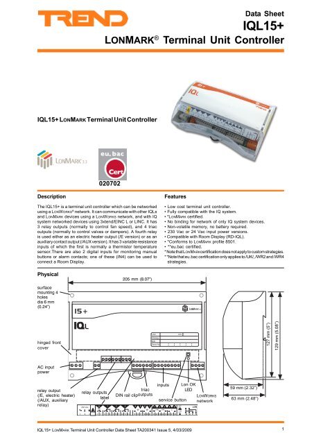
Data Sheet<strong>IQL15+</strong>HARDWARE<strong>Unit</strong>The <strong>IQL15+</strong> is a small terminal controller designed for surface orDIN rail mounting either inside or on the side of terminal units. Ithas a plastic housing with a hinged clear polycarbonate terminalcover and 4 point surface mounting.Input PowerThe <strong>IQL15+</strong> has both 230 Vac and 24 Vac input power options./230: This option requires 230 Vac +15% -10%, 50/60 Hz at upto 13 VA, which consists of up to 3VA internal power, plus thepower required by the triac (valve or damper) 24 Vac outputs whichis up to of 400 mA./24VAC: This option requires 24 Vac ±15%, 50/60 Hz, at upto 12.1 VA, which consists of up to 2.5VA internal power, plusthe power required by the triac (valve or damper) outputs whichis up to 400 mA. The 24 Vac input power neutral must be earthed,grounded, at the transformer secondary. The ac input powerneutral is internally connected to the IQL electronics earth,ground. Several IQLs may be supplied in parallel.The IQL input power earth, ground, terminal is isolated from thesupply neutral, and is connected to the chassis; this must beseparately earthed, grounded, locally.BackupThe data (shell firmware, strategy, parameters, logged data) isstored in flash memory which is non-volatile in the case of powerfailure. The flash memory is only written to at midnight or aftera write to the address module in order to prolong the life of theflash memory. Any changes to sensor or driver types should beterminated by a text comms reset command R(z=1) to immediatelywrite the changes to flash and reset the unit; note that thiscommand clears logged data and sets the time to zero. Any otherparameter changes (other than address module changes andchanges to current time) should be terminated by the text commscommand R(z=0) to immediately write the changes to flash.OutputsRelay Outputs (OUT1, 2, 3 - e.g. fan speed switches)IQL6789OUT1!Note that the IQL must be earthed, grounded(using its supply connector earth, ground,terminal)1011OUT2The internal supply is protected by an internal solid stateself-resetting thermal device rated at 500 mA.Service ButtonThis is used during the installation of the IQL into a LONWORKSnetwork management tool. This is only necessary under conditionsdescribed in the LONWORKS integration section below. During theinstallation process, the tool will request to be informed of thepresence of the IQL; this is done by pressing the ‘service’ button.Pressing the button also generates an alarm message forwardedby 3xtend/EINC L or LINC to its target alarm address (if set up)which identifies IQL by means of its Neuron chip ID; this can beused as an attribute to find the IQL’s device address and Lannumber.LONWORKSThe integral LONWORKS transceiver uses FTT (or LPT) which hasthe following features:-(1) Use of free bus topology enabling star, bus, or loopwiring simplifies installation and facilitates networkexpansion.(2) The bus uses two wires (twisted pair) which arepolarity independent with no need for screen.(3) The FTT runs at 78 k baud.(4) The FTT LONWORKS network may already be presentin a building, so the IQ system is able to make use ofan existing building bus and hence reduce installationcost.Lon OK IndicatorIt flashes approximately every 24 s while the local Lan of IQLsis being built, after which it stays on indicating that the IQL hassuccessfully communicated with at least one other IQ systemdevice on the LONWORKS network. If the IQL does not receive anymessages (i.e. a deaf IQL), it will flash every second.Triac Outputs (OUT4, 5, and OUT6, 7 - e.g. raise/lower valves)0 V" 8 = ?" 8 = ?IQL121314OUT3terminal numbersOUT4OUT5OUT6OUT7Relay Output (OUT8)- e.g. electric heater (/E version)or auxiliary relay (/AUX version)13 # $ % & 'COMCOM24~24~terminal numbers"#OUT8 ER1<strong>IQL15+</strong> LONMARK <strong>Terminal</strong> <strong>Unit</strong> <strong>Controller</strong> Data Sheet TA200341 Issue 5, 4/03/20093
<strong>IQL15+</strong>Data SheetHARDWARE (continued)InputsIN1 Resistance Input(normally thermistor)IN2 Resistance Input(normally potentiometer)IN3 Resistance InputIN4 Digital InputIN5 Digital Input2122232425262728IQLIN1COMIN2COMIN3IN4CIN5The SDU-LON (Smart Display <strong>Unit</strong>) is a wall mountingelectroluminescent display that can be connected to the LONWORKSbus and ‘attached’ to its IQL. It enables the user to view and adjustselected parameters within the controller. The SDU-LON has areal time clock that can set the controller’s time, it also providesit with a time zone and calendar features (see SDU data sheetTA200559).SensorsThe TB/TS provides a wall mounting thermistor space sensorthat can be connected to the <strong>IQL15+</strong> input 1 (see TB/TS datasheet TA200603). The TB/TS/K also provides setpoint adjustmentto connect to input 2. The TB/TS/KE has the TB/TS/K featuresplus an occupation override pushbutton to connect to input 4.The TB/TS/KEF has the TB/TS/KE features plus a fan speedcontrol switch to connect to input 3.terminal numbersInputs 1, 2, 3Variable resistance (analogue) inputs, 0 to 29 k The use of theinputs is defined by the strategy; the following are examples.Thermistor temperature sensor input (normallyinput 1). Thermistor inputs are scaled for a standard IQsystem thermistor (10 k at 25 °C, 77 °F). Scaling range2.5 °C to 60 °C (36.5 °F to 116 °F). Conversion accuracy±0.25 °C (±0.45 °F) over range (10 °C to 30 °C, 50 °F to86 °F).Potentiometer input (normally input 2). Scaled forstandard IQ system potentiometer (1 k to 11 k). Apotentiometer input is automatically self calibrating togive 0% to 100% of adjustment over full range ofpotentiometer. If required calibration may be set by turningpotentiometer to both ends of range, and waiting 6 secsat each endpoint.Fan Speed Control input (normally input 3). Inputresistance is set to one of five values by an externalswitch and decoded to give required fan speed selection(Off, Low manual, Medium manual, High manual, andAuto).Inputs 4, 5Volt free contact (digital) inputs. 5 Vdc supply via 10 k. Wettingcurrent 0.5 mA. Input 4 provides a TBus connection for use bythe RD-IQL (room display).DisplaysThe RD-IQL/K (Room Display) is a wall mounting temperaturesensor and 3 digit display with control and indication of setpoint.The RD-IQL/KOS also provides an occupation override switchand indication. The RD-IQL/KOSF also provides fan speed controland indication. The RD is connected to IN4. Some IQL configurationparameters must be changed for an RD-IQL to operate with theIQL (see strategy data sheet).Connecting an RD renders some of the normal featuresinoperative:RD-IQL/K: The RD’s potentiometer must be used, not IN2(if a potentiometer is required). A separate sensorconnected to IN1 may be used instead of the RD’s; thisis achieved by maintaining the normal sensor type forIN1. There will be no PIR or pushbutton input. A fan speedswitch connected to IN3 may be used.RD-IQL/KOS: The same as for RD-IQL/K but the /KOSgives use of its pushbutton.RD-IQL/KOSF: The same as for RD-IQL/KOS but the/KOSF gives use of its fan speed switch. A separate fanspeed switch connected to IN3 may be used instead ofthe RD’s; this is achieved by maintaining the normalsensor type for IN3.4 <strong>IQL15+</strong> LONMARK <strong>Terminal</strong> <strong>Unit</strong> <strong>Controller</strong> Data Sheet TA200341 Issue 5, 4/03/2009
Data Sheet<strong>IQL15+</strong>SYSTEMFull system details are covered by IQ System LONWORKS Product Engineering ManualLONWORKS busThe IQL is an IQ controller which uses the LONWORKS bus as itscommunications network. It is LONMARK certified and willcommunicate with other LONWORKS devices.LONWORKS IntegrationIn a LONWORKS system consisting only of IQ system devices noLONWORKS installation is required as IQ system LONWORKSproducts self-install. Installation onto a LONWORKS networkmanagement tool is only necessary if it is required to bind LONMARKdevices to the IQL strategy modules, if LINCs, pre-version 3.23,straddle a router, if other devices on the LONWORKS networkhave address conflicts with IQ system LONWORKS devices, orLONWORKS routers (e.g. IQLROUTERs) are used on an installedsystem. If one IQ system LONWORKS device is installed, all IQsystem LONWORKS devices must be installed.From a LONWORKS network perspective the IQL is supplied in aconfigured state i.e. it will install on the network with its addressset up and communicate using IQ system communications. It canbe set to an unconfigured state using a LONWORKS ManagementTool.IQL addressThe IQL device and Lan number are set up in the factory on arolling basis, so in a batch of IQLs, each will have a differentfactory address (printed on the unit’s label along with its NeuronID). IQ system LONWORKS devices on the same Lan must be onsame LONWORKS subnet (and hence same side of LONWORKSrouter). An IQL may be re-addressed by terse text comms(IqlTool2 recommended). New addresses should be written onthe unit’s label; a tear-off adhesive label strip with unit ID andaddress information can be used for a paper record e.g. logbook.CommunicationThe 3xtend/EINC L or LINC acts as an interface between the IQsystem Lan and the LONWORKS bus. It enables IQLs to communicatewith IQ system Supervisors by terse text comms and with IQsystem IQs using IC Comms. The 3xtend/EINC L is the preferableinterface, but if the system is installed on a LONWORKS ManagementTool, the LINC must be used. If the IQL is bound to other LONMARKdevices it communicates with them using Network Variables(NVs) as shown in accompanying table. The binding to a variableis done by using both SNVT (standardised network variabletype) and NV name for each variable. All the network variablesare described in the manual TE200292. Those required for theLONMARK node and the LONMARK profile 8501 compatibility areshown in the adjacent table (custom strategies may not havethese variables).IqlTool2IqlTool2 software tool connects directly to the LONWORKS segmentusing the LCI (LONWORKS Comms Interface) using adapter cablessupplied with the interface.It runs on a PC on which SET v5.1 or greater has been installed.IqlTool2 facilitates mapping the LONWORKS segment, resolvingLCIIqlTool2 (SET)IQLLONWORKSnetworkduplicate addresses on LONWORKS, water balancing (/WR2,/WR4, /WT2, /WT4 only), identifying using service button,associating with SDU-LON, monitoring inputs and exercisingoutputs, setting as a timekeeper, and configuring for RD. Itprovides access to text communications for changing moduleparameters (e.g. knobs, switches, changing a generic strategy).nvnameLONMARKNodeSNVTMandatory Network VariablesnviRequestnvoStatusSNVT_obj_reques tSNVT_obj_statu sOptional Configuration PropertiesnciNetConfignciMajDevVernciMinDevVerSNVT_config_srcSNVT_coun tSNVT_coun tManufacturer Defined SectionnciDomainIndexnciDomainWidenciMsgCodenciBufferSizenviCurrDateTimenviSecurity CodenvoGeneratorLONMARKProfile 8501SNVT_coun tSNVT_lev_discSNVT_coun tSNVT_countSNVT_time_stam pSNVT_coun tSNVT_coun tMandatory Network VariablesnviSpaceTempnvoSpaceTempnvo<strong>Unit</strong>StatusStrategyVar.SNVT_temp_p K2SNVT_temp_p S1SNVT_hvac_statu sOptional Network VariablesnviSetpointnviSetptOffsetnviOccManCmdnviFanSpeedCmdnvoEffectSetPtnvoEffectOccupnvoFanSpeednvoHeatPrimarynvoCoolPrimarySNVT_temp_p K1SNVT_temp_p K8SNVT_occupancy K6SNVT_temp_p K7SNVT_temp_p S2SNVT_occupancy S3SNVT_switch S6SNVT_lev_percent S4SNVT_lev_percent S5Mandatory Configuration PropertiesnciSndHrtBtnciSetpointsSNVT_time_se cSNVT_temp_setp tOptional Configuration PropertiesManufacturer Defined SectionnvoA7nvoA8nviA19nviA20nviA21nviB18_0nviB18_1nviB18_2nviB18_3nviB18_4nviB18_5nviB18_6nviB18_7nvoB1_0nvoB1_1nvoB1_2nvoB1_3nvoB1_4nvoB1_5nvoB1_6nvoB1_7SNVT_temp_p S7SNVT_temp_p S8SNVT_temp_p K3SNVT_temp_p K4SNVT_temp_p K5SNVT_switch W1SNVT_switch W2SNVT_switch W3SNVT_switch W4SNVT_switch W5SNVT_switch W6SNVT_switch W7SNVT_switch W8SNVT_switchI1SNVT_switch I2SNVT_switch I3SNVT_switch I4SNVT_switch I5SNVT_switch I6SNVT_switch I7SNVT_switch I8Table of Network Variables for <strong>IQL15+</strong>LabelLONWORKS ManagedLONWORKS domainindexLONWORKS domain wideLONWORKS messagecodeRouter buffer sizeRemoteSpaceTem pSpace Tem pRemote SetpointRemote SP OffsetRemote OccRemote Fan SpdSetpointOccupanc yFan SpeedHeating DemandCooling DemandEffect Fan SpeedOCC DeadbndStandby DeadbndNOCC DeadbndO=4Pipe I=2PipeSummer ModeElec DisableO=Water I=Ai rWindow ModeO=Pb I= PIRFrost ConditionRemote Shutdow nFan Enabled<strong>Unit</strong> Occupied<strong>Unit</strong> Unoccupie d<strong>Unit</strong> in Standb y<strong>IQL15+</strong> LONMARK <strong>Terminal</strong> <strong>Unit</strong> <strong>Controller</strong> Data Sheet TA200341 Issue 5, 4/03/20095
<strong>IQL15+</strong>Data SheetINSTALLATIONThe <strong>IQL15+</strong> must be installed inside a protective case if not installed well outside normal reach (e.g. behind a false ceiling).The /USA/UL/ 24VAC unit is rated as ‘UL916 listed open energy management equipment’.It should be mounted either on DIN rail or flat surface (via 4 hole mounting). The installation involves the following procedure:Mount the unit in positionConnect input power (do not switch on)Earth (ground) unitConnect LONWORKS networkConnect I/OSwitch on power to unitCheck IQ system communicationsConfigure core module parameters if requiredInstall on LONWORKS Management Tool if required (see LONWORKS integration above) and bind any network variables.Configure strategy parameters if requiredConfigure rest of systemTest systemNote: If installation on a LONWORKS ManagementTool is required, the installer must have LONWORKS engineerng expertiseThe installation procedure is coverd by <strong>IQL15+</strong>/xxx Installation Instructions, TG200344. If supplied with a custom strategy, also seeappropriate strategy installation instructions.6 <strong>IQL15+</strong> LONMARK <strong>Terminal</strong> <strong>Unit</strong> <strong>Controller</strong> Data Sheet TA200341 Issue 5, 4/03/2009
Data Sheet<strong>IQL15+</strong>CONNECTIONSLONWORKS networkThe LONWORKS network has free bus topologyLON*Terminate LONWORKSbus at one end only*6 A H E = J HInput Power/230! 8 = ? ! L N E29 30 31 32LONWORKS LONWORKSnetworknetworkpolarity independentTerminatore.g.LONTERMINATORRecommended cables shown in specificationsection below. Do not use screened cable.*100 F, 50 V min100 F, 50 V min6 A H E = J H*6 A H E = J HDo not allowwires tocross on aloopWARNING: This apparatusmust be earthed, grounded.(using earth, ground, terminal)Clean earths, grounds,consisting of short =1.5 mm, 16 AWG) wired toa substantial earthed,grounded, point (e.g. cabletray) are recommended.# ) 5 JH= JA C O 1,5 A HE= 5/24VAC" 8 = ?1 2 3InputsClass 224Vac ! " #+ + +Earth, ground, 24 Vac supplyneutral at transformer ! " # $ % &Relay OutputA room display (RD) can beconnected to IN4.&- 4 (10 A max.)Note that terminal types COM andC should not be connectedtogether." # Electric Heater (/E only)If switching an electric heater, asuitably rated thermal cutout shouldbe fitted in series with the heatersupply.Auxiliary Relay Output(/AUX only)Relay Outputs (5 A max.)!$ % & ' ! "Triac Outputs400 mA max. shared beween all triacoutputs used" # $ % " 8 " 8 # $ % & ' See strategy data sheet for input/output connection details.<strong>IQL15+</strong> LONMARK <strong>Terminal</strong> <strong>Unit</strong> <strong>Controller</strong> Data Sheet TA200341 Issue 5, 4/03/20097
<strong>IQL15+</strong>Data SheetDISPOSALCOSHH (Control of Substances Hazardous to Health - UKGovernment Regulations 2002) ASSESSMENT FOR DISPOSALOF IQL CONTROLLER. No parts affected.RECYCLING .All plastic and metal parts are recyclable. The printed circuitboard may be sent to any PCB recovery contractor to recoversome of the components for any metals such as gold and silver.WEEE Directive :At the end of their useful life the packaging andproduct should be disposed of by a suitablerecycling centre.Do not dispose of with normal household waste.Do not burn.8 <strong>IQL15+</strong> LONMARK <strong>Terminal</strong> <strong>Unit</strong> <strong>Controller</strong> Data Sheet TA200341 Issue 5, 4/03/2009
Data Sheet<strong>IQL15+</strong>ORDER CODESUK Order CodesUSA Order Codes<strong>IQL15+</strong>/[strategy]/[option]/[power]e.g. <strong>IQL15+</strong>/WR4/E/24VAC : not available in USA <strong>IQL15+</strong> controller with 24 Vac supply and generic strategy set forWater Side, 4 Pipe, Raise/Lower (floating) with Electric Heateroutput.<strong>IQL15+</strong>/[strategy]/E/USA/UL/24VAC 882001292<strong>IQL15+</strong> controller with 24 Vac supply and [strategy], with electricheater output for USA. UL rated.[ strategy][ option][power]For standard strategies and options, see <strong>IQL15+</strong>/xxxStandard Strategies Data Sheet TA200367/ E ElectricHeater output/ 24VAC24 Vac Supply/ AUX AuxiliaryRelay output/ 230230 Vac SupplyLONTERMINATOR 882000350 Universal LONWORKS terminator (see LONTERMINATOR data sheetTA200229)SDU-LON not available in USA Wall mounting Smart Display unit enables display and adjustmentof control parameters. Connects to a LONWORKS network.SDU-LON/WSA/USA 882001470 Wall mounting Smart Display unit enables display and adjustmentof control parameters, with wall sensor adaptor plate. Connectsto a LONWORKS network.IQLROUTER/24VAC not available in USA IQL Router with 24Vac power option.IQLROUTER/230 not available in USA IQL Router with 230 Vac power option.IQLROUTER/USA/UL/24V 882001300 IQL Router with 24Vac power option.TB/TS 882000540 Wall mounting thermistor space temperature sensorTB/TS/K 882000560 As TB/TS plus setpoint adjustmentTB/TS/KE 882000580 As TB/TS/K pus occupation override push buttonTB/TS/KEF not available in USA As TB/TS/KE plus fan speed control switchRD-IQL/K 882001530 Wall mounting Room Display comprising temperature sensor, 3 digitdisplay with control and indication of setpointRD-IQL/KOS 882001540 As RD-IQL/K plus occupation override switch and indicatorRD-IQL/KOSF 882001550 As RD-IQL/KOS plus fan speed control and indicatorNETB/LONC/[version]/FTT/230 not available in USA LONMARK Object Node <strong>Controller</strong> enables communication with otherLONMARK devices, 230 Vac supplyNETB/LONC/[version]/FTT/24 not available in USA LONMARK Object Node <strong>Controller</strong> enables communication withother LONMARK devices, 24 Vac supplyVersion/ EN48A/FTT48 enumerated inputs/ IN48A/FTT48 integer inputs/ FL48A/FTT48 floating inputs/ EN48S/FTT48 enumerated outputs/ IN48S/FTT48 integer outputs/ FL48S/FTT48 floating outputs/GEN/FTTinputs/outputs8 integer, + 8 floating, + 8 enumerated inputs,+ 8 integer, +8 floating + 8 enumerated outputsNETB/LONC/GEN/FTT/USA/UL/24 882000290 UL rated boxed version of LONC requiring 24 Vac input power.*3XTEND/EINC L/230 not available in USA Node controller which enables LONWORKS bus to be used as partof IQ System. Connects IQLs to IQ System current loop networkand Ethernet. 230Vac power.*3XTEND/EINC L/24 not available in USA Node controller which enables LONWORKS bus to be used as partof IQ System. Connects IQLs to IQ System current loop networkand Ethernet. 24 Vac power.*3XTEND/EINC L/USA/UL/24 882001600 UL rated node controller which enables LONWORKS bus to be usedas part of IQ System. Connects IQLs to IQ System current loopnetwork and Ethernet. 24 Vac power.*NETB/LINC/FTT/USA/UL/24 882000280 UL rated node controller which enables LONWORKS bus to be usedas part of IQ System. Connects IQLs to IQ System current loopnetwork. 24 Vac power.*NETB/LINC/FTT/230 not available in USA Node controller which enables LONWORKS bus to be used as partof IQ System. Connects IQLs to IQ System current loop network,230 Vac power.*NETB/LINC/FTT/24 not available in USA Node controller which enables LONWORKS bus to be used as partof IQ System. Connects IQLs to IQ System current loop network,24 Vac power.*Note that the 3xtend/EINC L should be used as preference; LINC must be used if system installed on a LONWORKS Management ToolLCI/USB 882001300 LONWORKS Commissioning Interface. Portable LONWORKS nodewhich connects to PC to LonWorks using a USB connection.TP/1/0/16/HF/200 not available in USA 200 metres (218 yds) unscreened single twisted pair cable suitablefor wiring LONWORKS bus.<strong>IQL15+</strong> LONMARK <strong>Terminal</strong> <strong>Unit</strong> <strong>Controller</strong> Data Sheet TA200341 Issue 5, 4/03/20099
<strong>IQL15+</strong>Data SheetSPECIFICATIONSElectricalInput Power Supply/230 :230 Vac -10% +15%, 50/60 Hz/24VAC:24 Vac ±15%, 50/60 HzInput Power Supply Consumption/230 :Up to 13 VA which consists of 3 VA internalpower plus power to triac outputs./24VAC:Up to 12.1 VA which consists of 2.5 VAinternal power plus power to triac outputs.In both cases the maximum current sharedbetween the triac outputs is 400 mA.CPU:3 processor Neuron chipMemory:64 kbytes flash memory, 8 kbytes RAMBattery:no battery required (data stored in flashmemory)Clock:software clock (1 minute resolution)LONWORKS network :FTT - Free topology, 78 k baud, transformerisolated. Single termination (RC network).Can also use loop powered free topology,LPT.LONWORKS FTTdistance:Maximum bus length, node to node distancedepends on cable type:Recommended CablesMax bus lengthMax nodenode500 m (545B elden 85102500m (545 yds)yds)IQ SystemTP/1/0/16/HF/200 500m (545 yds) 400 m (430 yds)(Belden 8471)U L Level IV, 22 AWG 500m (545 yds)400 m (430 yds)J Y(St) Y2 x 2 x 0.8 500m (545 yds)320 m (350 yds)T IA568A Cat. 5, 24 AWG 450m (490 yds)250 m (270 yds)Note that this does not include cable recommended for the IQ systemcurrent loop Lan.Fuse:Solid state self-resetting, protects at 500 mA.InputsIN1, 2, 3:Variable resistance inputs, 0 to 29 k, Bridgesupply 5 Vdc.IN4, 5:Volt free contact inputs. 5 Vdc supply through10 k. Wetting current 0.5 mA. IN4 providesTBus for connection of RD.OutputsOUT1, 2, 3OUT4/OUT5OUT6/OUT7OUT8:Digital outputs: Changeover relay contacts.Output rated at 5 A maximum at 240 Vac(cosø>=0.4), and 24 Vdc (resistive load).Reduce to 2 A for 24 Vdc (inductive load,T=0.4), and 28 Vdc (resistive load).Reduce to 2 A for 24 Vdc (inductive load,T


