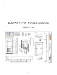
TurboCAD Pro V15 - Understanding Workplanes
TurboCAD Pro V15 - Understanding Workplanes
TurboCAD Pro V15 - Understanding Workplanes
- No tags were found...

Create successful ePaper yourself
Turn your PDF publications into a flip-book with our unique Google optimized e-Paper software.
Since this is a frequent need, many users create a shortcut tool on their <strong>TurboCAD</strong> desktop or use theshort-cut keys. Below is an image of the tool the author has on his desktop. A text toolbar is created firstand then the text icon is changed to the down arrow icon via the 'change button image' customizedialogue.Many users find the above part especially confusing and often ask why? In essence every item is createdon its own workplane even though it looks like they are on the same workplane. Issues don't arise untilthe 2D objects are copied and then issues will be seen when functions such as line length, offset, paralleland so forth are employed. It is just something a user has to get used to as it has been this way for allversions of <strong>TurboCAD</strong>. Eventually a user will come to know instinctually when to place their 2Dobjects on the workplane.Because the "table" is required continually while drawing the developers of <strong>TurboCAD</strong> have includedseveral workplane tools to facilitate the move quickly and efficiently.Show / Hide Workplane Workplane by Active View Workplane by World Workplane by Entity Workplane by 3 Points Workplane by Z Axis Previous Workplane Set Named Workplane Workplane Origin Edit Current Workplane Workplane by FacetAuto Workplane by FaceFit Workplane to Window Show/Hide Intersections between WorkPlane and 3D ObjectsThis tutorial assumes that the beginner has studied the desktop to some degree and can locate most ofthe tools. Since there are endless desktop configurations that can be set up in <strong>TurboCAD</strong> the author has5
Select the circle on the box and delete it.Select the box. Tab into the Inspector Bar and enter 0 in the X, Y and Z position fields. Press Enter tomove the box to a common location for all readers.With the box still selected, select Zoom Extents from the menu bar at the top of the <strong>TurboCAD</strong> desktop.Select the Fit Workplane to Window tool from the Workplane toolbar. Left mouse click in a clear areaof the drawing area to deselect the box.Switch to Right view.28
Because the default reference point of the box is at the center of the box, when the box was moved togrid location 0,0,0 the bottom of the box is no longer on the workplane, it is 1.75 inches below theworkplane. The box has moved, not the workplane so the workplane is now in the middle of the box,and consequently at the center of all three (X, Y, Z) axis'.Switch to Isometric SE view.Preparation for the next workplane tool explanation will now take place.Select the Rectangle tool from the Line toolbar.In a clear area of the drawing snap an 8 inch square to the grid using two G SEKE snaps.Press Space Bar to exit the tool.Select the new rectangle and note the relationship of the X, Y, Z handles to the world coordinate icon.They are the same. The square is on the X-Y plane.With the rectangle still selected, select the Copy in Place tool from the BCiTool_GM toolbar 1X (onetime).The only indication that a copy has been made is theusers knowledge that they have left mouse clicked thetool icon.29
Left mouse click on the green Z rotation handle to pick it up (click and release). Note which rotationfield on the Inspector bar changes as the cursor is moved.Tab into the Inspector Bar and enter 270 in the Y Rotation field (rotating on the Y axis). Press Enter.Note the relationship to the world plane icon. This rotated square now represents the Z-Y plane.With the rectangle still selected, select the Copy in Place tool from the BCiTool_GM toolbar 1X.Left mouse click on the green Y rotation handle to pick it up (click and release). Begin to rotate therectangle counterclockwise and when the X and the Y Rotation fields change to 90 Tab into theInspector Bar and enter 0 in the Y Rotation field. Press Enter.30
Note the relationship to the world plane icon. This rotated square now represents the Z-X plane.Select the three rectangles. This can be done by dragging the selection cursor around part of all three, ora user can press and hold the Shift key down and left click them one at a time to add them to the currentselection. (With this method, a user can also deselect objects with a left mouse click if the object isalready selected. Release the Shift key when all three are selected)Left mouse click on the reference point of the selection to pick it up. Move the cursor over to the edge ofthe box that was created earlier and E SEKE snap the squares to the box. In progress below.Once snapped into place note the position on the Inspector Bar.Press Esc to deselect the selection.Switch to Left view.31
Like so. Note the grid change, the workplane indicator change and the UCS icon change. Note also thedirection of the Z indicator in the UCS icon. It is pointing up in this case.Switch to Front view. Note the workplane indicator location.Switch to Isometric SE view.Select the Cylinder tool from the 3D Object toolbar.N SEKE snap the first point of the circle to diagonal line on the top of the box. Move cursor to the left ashort distance and then left mouse click to place the second point. In progress below.Move the cursor upward and at the same time note the direction of Z on the UCS icon and the numbersin the Height field of the Inspector Bar. Z is pointing upward in which case the numbers in the Heightfield should be should be positive numbers, and they are.47
Move the cursor downward and at the same time note the direction of Z on the UCS icon and thenumbers in the Height field of the Inspector Bar. Z is pointing upward in which case the numbers in theHeight field should be negative numbers, and they are.The illustration below shows the positive / negative relationship of the coordinate system as it pertains toworkplanes.48
Press Space Bar to exit the tool.Select the box. Left mouse click on the reference point of the selection to pick it up. Move the cursor tothe edge of the larger box and E SEKE snap the selection in place. In progress below.Switch to Front view to confirm the smaller box is inside the original box.Switch back to Isomeric SE view.Press Esc to deselect the selection.Select the Workplane by Facet tool from the Workplane toolbar.The Workplane by Facet tool, as seen near the beginning of the tutorial, is used to select specific faces(facets) on objects with which to place the workplane.With the Workplane by Facet tool active move the cursor over some of the faces in the drawing. Do notleft mouse click at this time. Just move around.63
Here on the front face of the larger box.Here on the top face of the cylinder.Place the cursor over the "hidden" face of the smaller box as indicated in the picture below. The face onthe large box will be highlighted at this point.Press the Page Down key on the keyboard to move down to the hidden facet.64